EP0829146B1 - Frequency tracking for communication signals using m-ary orthogonal walsh modulation - Google Patents
Frequency tracking for communication signals using m-ary orthogonal walsh modulation Download PDFInfo
- Publication number
- EP0829146B1 EP0829146B1 EP97918684A EP97918684A EP0829146B1 EP 0829146 B1 EP0829146 B1 EP 0829146B1 EP 97918684 A EP97918684 A EP 97918684A EP 97918684 A EP97918684 A EP 97918684A EP 0829146 B1 EP0829146 B1 EP 0829146B1
- Authority
- EP
- European Patent Office
- Prior art keywords
- frequency
- correlation
- walsh
- binary representation
- tracking loop
- Prior art date
- Legal status (The legal status is an assumption and is not a legal conclusion. Google has not performed a legal analysis and makes no representation as to the accuracy of the status listed.)
- Expired - Lifetime
Links
- 238000004891 communication Methods 0.000 title claims abstract description 33
- 230000006870 function Effects 0.000 claims abstract description 130
- 239000013598 vector Substances 0.000 claims abstract description 43
- 238000000034 method Methods 0.000 claims description 50
- 238000001914 filtration Methods 0.000 claims description 6
- 238000012935 Averaging Methods 0.000 claims description 4
- 238000001514 detection method Methods 0.000 claims 1
- 230000009466 transformation Effects 0.000 abstract description 2
- 230000000875 corresponding effect Effects 0.000 description 22
- 239000011159 matrix material Substances 0.000 description 15
- 230000008569 process Effects 0.000 description 9
- 238000012545 processing Methods 0.000 description 7
- 230000002596 correlated effect Effects 0.000 description 6
- 238000001228 spectrum Methods 0.000 description 5
- 230000008901 benefit Effects 0.000 description 4
- 230000004044 response Effects 0.000 description 4
- 230000001413 cellular effect Effects 0.000 description 3
- 238000010586 diagram Methods 0.000 description 3
- 230000000694 effects Effects 0.000 description 3
- 230000001174 ascending effect Effects 0.000 description 2
- 230000001427 coherent effect Effects 0.000 description 2
- 238000007796 conventional method Methods 0.000 description 2
- 239000000654 additive Substances 0.000 description 1
- 230000000996 additive effect Effects 0.000 description 1
- 230000005540 biological transmission Effects 0.000 description 1
- 238000004364 calculation method Methods 0.000 description 1
- 238000009795 derivation Methods 0.000 description 1
- 230000003116 impacting effect Effects 0.000 description 1
- 238000013507 mapping Methods 0.000 description 1
- 230000007246 mechanism Effects 0.000 description 1
- 230000009467 reduction Effects 0.000 description 1
- 230000003595 spectral effect Effects 0.000 description 1
- 230000002123 temporal effect Effects 0.000 description 1
Images
Classifications
-
- H—ELECTRICITY
- H04—ELECTRIC COMMUNICATION TECHNIQUE
- H04B—TRANSMISSION
- H04B1/00—Details of transmission systems, not covered by a single one of groups H04B3/00 - H04B13/00; Details of transmission systems not characterised by the medium used for transmission
- H04B1/69—Spread spectrum techniques
- H04B1/707—Spread spectrum techniques using direct sequence modulation
- H04B1/7073—Synchronisation aspects
- H04B1/7075—Synchronisation aspects with code phase acquisition
-
- H—ELECTRICITY
- H04—ELECTRIC COMMUNICATION TECHNIQUE
- H04B—TRANSMISSION
- H04B1/00—Details of transmission systems, not covered by a single one of groups H04B3/00 - H04B13/00; Details of transmission systems not characterised by the medium used for transmission
- H04B1/69—Spread spectrum techniques
- H04B1/707—Spread spectrum techniques using direct sequence modulation
- H04B1/7073—Synchronisation aspects
- H04B1/7085—Synchronisation aspects using a code tracking loop, e.g. a delay-locked loop
-
- H—ELECTRICITY
- H04—ELECTRIC COMMUNICATION TECHNIQUE
- H04B—TRANSMISSION
- H04B1/00—Details of transmission systems, not covered by a single one of groups H04B3/00 - H04B13/00; Details of transmission systems not characterised by the medium used for transmission
- H04B1/69—Spread spectrum techniques
- H04B1/707—Spread spectrum techniques using direct sequence modulation
- H04B1/709—Correlator structure
-
- H—ELECTRICITY
- H04—ELECTRIC COMMUNICATION TECHNIQUE
- H04L—TRANSMISSION OF DIGITAL INFORMATION, e.g. TELEGRAPHIC COMMUNICATION
- H04L27/00—Modulated-carrier systems
- H04L27/0014—Carrier regulation
- H04L2027/0044—Control loops for carrier regulation
- H04L2027/0063—Elements of loops
- H04L2027/0065—Frequency error detectors
Definitions
- the present invention relates generally to frequency tracking loops used in communication systems, and more particularly to a frequency tracking loop for use in a communication system employing orthogonal Walsh modulation.
- PLL Phase Locked Loop
- the present invention comprises apparatus and method for tracking the carrier frequency used in a communication system employing M-ary orthogonal modulation in accordance with the claims which follow.
- the invention may be implemented alone, or as part of a larger demodulation system.
- a preferred embodiment of the invention operates in an environment or system, such as a wireless spread spectrum communication system, where M-ary orthogonal Walsh modulation is employed.
- the invention includes a frequency tracking loop comprising a rotator or rotation means, a correlator or correlation means, a discriminator or discrimination means, and a filter or filtering means.
- the rotation means receives an input signal and a frequency offset estimate and produces a frequency shifted input signal, the frequency shift being proportional to the frequency offset estimate.
- the correlation means determines the correlation between a set of Walsh functions and the frequency shifted input signal, and produces a correlation vector.
- the correlator output may also be used as a data output as well.
- the discrimination means receives the correlation vector and produces a frequency error signal ("current error”).
- the filtering means accumulates the resulting frequency error signals to produce the frequency offset estimate used by the rotator means ("residual error").
- the correlation vector produced by the correlator or correlation means includes a plurality of correlation results, each correlation result being the result of a correlation between the frequency shifted input signal and a single Walsh function.
- Each correlation result has an index value, which may be represented in binary notation, with each index value corresponding to a particular Walsh function.
- the discrimination means determines the current error of the frequency tracking loop as follows. First, the Walsh index of the correlation result with the highest signal energy contained in the correlation vector is determined. This value is selected as representing the most likely transmitted Walsh function or code, and as containing the largest amount of the transmitted signal component. One of the bits of the binary representation of the Walsh index associated with this correlation result is then inverted to generate a Walsh index of another Walsh function. The correlation result from the correlation means having this second index is selected, and a cross product is formed between this second result and the first selected result. That is, the imaginary part of a product between the correlation result with the highest energy level and the complex conjugate of a second correlation result corresponding to a bit reversed index for the first result, is then determined. The resulting cross product value that is determined from this process is proportional to the current error of the frequency tracking loop.
- the most significant bit (MSB) of the binary representation of the Walsh index associated with the highest energy output from the correlator is the bit that is reversed.
- the correlation means output for the Walsh index selected by reversing the first MSB is predicted to contain the second largest signal component when there is a frequency tracking error.
- the discriminator determines the current error of the frequency tracking loop by substituting correlation results corresponding to other inverted Walsh index bits into the cross product calculation.
- the correlation means output corresponding to reversing the second MSB is predicted to provide the third largest transmitted signal component
- the correlation means output for reversing the third MSB is predicted to provide the fourth largest signal component, and so forth. Therefore, each particular index bit is selected for reversal based on a desired or predicted amount of signal energy, and its relative output offset, to use for determining the current error of the frequency tracking loop. Selecting higher order significant bits generally provides better steady state loop performance while lower order bits provide a higher pull-in range.
- the discriminator determines the current error by averaging various combinations of correlation results, each determined through bit manipulation or reversal, as described above. Where even greater accuracy is required, the average of two or more results obtained from differing types of processing (cross products), as described above, can be produced.
- the present invention comprises a system and method for implementing a frequency tracking loop in a communication system employing M-ary orthogonal Walsh modulation of communication signals.
- a preferred embodiment of the invention is discussed below, together with a number of alternative embodiments. Where specific steps, configurations and arrangements are discussed, it should be understood that this is done for illustrative purposes only.
- the frequency tracking loop of the present invention operates to accomplish much the same function as conventional frequency tracking loops.
- the frequency tracking loop of the present invention may be implemented alone, or as an integral part of a system demodulator. In either case, the frequency tracking loop tracks the center of the carrier frequency of a modulated communication signal to enable accurate demodulation. Thus, as the center of the carrier frequency drifts, the frequency tracking loop automatically shifts the received signal to permit accurate demodulation.
- the frequency tracking loop also shifts the received carrier. The response of the frequency tracking loop therefore ultimately determines the overall effectiveness and accuracy of the demodulator.
- the frequency tracking loop of the present invention operates in a communication system employing M-ary orthogonal Walsh modulation.
- data to be transmitted is mapped into digital values, with each digital value corresponding to the index of one Walsh function.
- the Walsh function represented by this index value can then be transmitted (e.g., as a series of "chips").
- each series of chips can be correlated with the predefined universe of Walsh functions to determine which Walsh function was received. The results of this correlation process are used to determine the "most likely" Walsh function being transmitted during any given reception period.
- the digital value of the index corresponding to that Walsh function represents the data that was most likely transmitted.
- Walsh code modulation is utilized by the preferred embodiment of the present invention.
- the derivation of Walsh codes is more fully disclosed in U.S. Pat. No. 5,103,459 (the '459 patent) entitled “System And Method For Generating Signal Waveforms In A CDMA Cellular Telepnone System” .
- the '459 patent is assigned to the assignee of the present invention.
- orthogonal binary sequence sets are known for most lengths which are multiples of four and less than two hundred.
- Walsh functions are derived from Walsh function matrices, also known as Hadamard matrices.
- the first two Hadamard matrices of orders 2 and 4 can be represented as:
- a Walsh function is simply one of the rows of a Walsh matrix (Hadamard matrix), and a Walsh function matrix of order 'L' is a square matrix containing L functions or sequences, each being L chips (bits) in length.
- a Walsh function of order n (as well as other orthogonal functions) has the property that over an interval of L chips (e.g., an L-length code symbol) in a string of chips, the correlation between all of the different functions within a set of L-length functions is zero, provided there is temporal alignment. This is independent of data modulation ( ⁇ 1) or function. This is easily understood by observing that exactly half of the chips or bits in every function differ from those in all other functions.
- the Walsh function size or code sequence length L is set equal to the desired number of orthogonal code sequences to be accommodated by the communication system.
- the Walsh functions are typically configured as a pre-defined set or table of binary sequences comprising 64 Walsh functions, each having a 64 chip length, such as listed in the IS-95 system specification referenced below.
- Walsh codes make them ideal for use in transmitting data in CDMA communications systems. Furthermore, as will be described below, the inventors have discovered that the unique properties of Walsh codes also permit them to be used to increase the effectiveness of a frequency tracking loop.
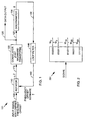
- FIG. 1 depicts a block diagram of a frequency tracking loop 101 constructed and operating according to the present invention.
- Frequency tracking loop 101 employs a rotation element or rotator 110 , a correlation element or correlator 120 , a discriminator 130 , and a loop filter 140 .
- An exemplary correlator is a Fast Hadamard Transformation (FHT) device.
- FHT Fast Hadamard Transformation
- other correlators known in the art can be employed within the teachings of the invention, as long as they provide structured Walsh function index outputs or ordering.
- frequency tracking loop 101 tracks the center frequency of the carrier used to transmit data in any communication system where M-ary Walsh code modulation is used.
- M-ary Walsh code modulation is used.
- a communication system is the reverse link transmission system of a cellular CDMA system such as that described in the IS-95 system specification entitled "Mobile Station-Base Station Compatibility Standard For Dual-Mode Wideband Spread Spectrum Cellular System," .
- discriminator 130 determines a current frequency error between the carrier center frequency of a received signal and the correlator/demodulator loop, which typically contains an FHT.
- This determination (a frequency error signal 132 (ê)) is input to a loop filter 140, which accumulates current frequency error signals 132 and then generates a residual frequency offset estimate signal 142 (f and).
- Residual frequency offset estimate signal 142 is input to rotator 110 , which shifts subsequently received input signals 102 by a value equal to frequency offset estimate signal 142 before passing the shifted input signal 112 (f-f and ) to a Fast Hadamard transform (FHT) type correlator 120.
- FHT correlator 120 acts on this input to produce a correlation vector 122 , which is used by discriminator 130 to complete the loop.
- FHT correlator 120 also includes a data output 125 which outputs received data for use in actual signal processing.
- a received communication signal 102 (of offset frequency f) is first input to rotator 110 .
- Rotator 110 shifts the frequency of the input signal 102 to compensate for variations in the center frequency of the carrier signal.
- the amount by which this frequency is shifted is based on the value of the frequency offset estimate signal 142, which is determined by discriminator 130 and loop filter 140, as described below.
- the initial value of this estimate can be selected at random, empirically for the particular system, or using other known techniques, and could be stored in a memory element.
- the frequency shifted input signal 112 (f-f and ) is then input to FHT correlator 120.
- FHT correlator 120 performs a correlation on the frequency shifted input signal 112 and generates a set of output values forming a correlation vector 122 . In performing this correlation, FHT correlator 120 takes advantage of the properties of Walsh code modulation explained herein.
- each Walsh function is represented by 64 Walsh “chips,” with each Walsh chip being ⁇ 1.
- each group of six symbols is use to select one corresponding Walsh function, which is transmitted in place of the data symbols.
- W n each transmitted Walsh code (or function)
- a received, modulated signal can be thought of as being comprised of a series of Walsh functions W n , within the predefined universe of sixty-four Walsh functions, with every W n representing N symbols. It is important to note, however, that the present invention is equally operable over any size set of Walsh functions, or for other mappings of data symbols (N ⁇ 6) to Walsh functions.
- a particular Walsh function e.g., W n
- W k a particular Walsh function
- W k a predefined set of Walsh functions
- the fast Hadamard transform (FHT) correlator 120 of frequency tracking loop 101 performs this correlation.
- the rotated input signal 112 is input to FHT correlator 120 .
- FHT correlator 120 takes the complex received signal 112 and performs a matrix multiplication on it.
- FHT correlator 120 contains a 64-by-64 matrix (not shown) which represents the predefined universe of Walsh functions.
- FHT correlator 120 takes the rotated input signal 112 and correlates (multiplies) it with each 64 bit vector in the matrix. This process can be thought of as Walsh decoding, as understood in the art.
- the result of this correlation is a 64-by-1 vector which represents the correlation of the rotated input signal 112 with each vector in the matrix.
- each non-zero value in the vector represents a likelihood that the associated input vector 112 and the matrix vector are non-orthogonal (e.g., that the associated input vector is that particular W k ).
- the ideally non-zero outputs may have less energy than some other outputs generated because of noise. This makes the process of detecting of the correct Walsh function W n being received very difficult at best, with current techniques.
- FHT 120 may accomplish the correlation processing in any of several ways. In addition to matrix multiplication as described above, FHT 120 may be constructed using a series of criss-cross networks which perform a series of summations (add/subtract). Furthermore, FHT 120 may operate on input vector 112 serially or in parallel.
- FHT processors of this type are known in the art such as shown and described in U.S. Patent No. 5,561,618 entitled “Method And Apparatus For Performing A Fast Hadamard Transform," or U.S. Patent Application No. 08/424,773 entitled “Method And Apparatus For Unified Signal Modulation,” each of which is assigned to the assignee of the present application.
- FHT correlator 120 determines or assigns the Walsh index associated with the value of each correlation that was performed.
- the index value is known or assumed from the ordering of the outputs in a predetermined fashion, such as the ascending order 0 - 63 pattern of FIG. 2.
- this index is a binary representation of the Walsh function matrix entry which was correlated with the input signal.
- a 6-bit index value is associated with each correlation output (e.g., 000000 through 111111 representing Walsh functions W 0 through W 63 respectively).
- correlator 120 can be constructed to present the correlation outputs in other orders or patterns, such as even and odd, as long as the absolute index value of k is known.
- FHT correlator 120 Upon completion of Walsh demodulation for any received signal, FHT correlator 120 outputs a correlation vector 122 .
- This correlation vector includes the 64-by-1 vector representing the correlation that was performed with each of the set of Walsh functions, and has associated Walsh function indices that correspond to each correlation result.
- FHT 120 also includes a data output 125 which outputs correlated received signal data or Walsh function data for further signal processing to produce transmitted data symbols.
- the Walsh correlation process is affected by any variation or drift in the carrier frequency of the received signal (or local oscillator). This is because any such variation affects the orthogonality of the received Walsh functions by impacting spectral alignment of the received chip values ( ⁇ 1) with the correlated sequences.
- Frequency tracking loop 101 employs a discriminator 130 to overcome these difficulties.
- Discriminator 130 receives the correlation vector 122 from FHT correlator 120 and generates a frequency error signal 132 which is input to loop filter 140 . Discriminator 130 accomplishes this by taking advantage of certain unique properties associated with Walsh functions as used in communication systems.
- Walsh functions as used in communication systems possess certain unique properties.
- One such property pertains to the relationship between the energy present in the correlation output for the Walsh function that was actually transmitted (the "correct" function) and all other outputs for correlated Walsh functions in the predefined universe of functions. This property is described in detail below.
- a predefined set of Walsh functions is used to modulate a data signal, or a predefined sub-set of a known set.
- Walsh function modulation a unique relationship exists between the index of the Walsh function actually used to modulate the data signal, and all other Walsh functions in the predefined universe of functions. This relationship derives from the relationship between the energy present in each Walsh function correlation, and the frequency error between the carrier center frequency and the frequency tracking loop/correlator.
- the first case that must be considered is when there is no residual frequency error.
- signal energy will be present only in the Walsh function actually transmitted (e.g., in a noiseless signal).
- this is represented by the presence of signal energy in only one of the FHT correlator 120 correlation outputs (e.g., the one corresponding to the transmitted Walsh symbol). All other FHT correlator outputs would contain only noise, although, in an actual communication system, the noise energy may appear larger at the correlator outputs than signal energy.
- the transmitted signal will appear to "leak" into the outputs associated with other decoded Walsh functions.
- this would appear as a reduction of energy in the FHT correlator 120 output representing the Walsh function that was actually transmitted, and an increase in signal energy in the correlation outputs corresponding to other Walsh functions.
- the amount of this leakage is proportional to the frequency error.
- Equation 1 E user represents the power of input signal 102
- T w is the Walsh chip duration
- W k [i] is the i th chip of the k th Walsh function
- (W m ) denotes the Fourier transform of the m th Walsh function.
- Equation 2 The relationship expressed in Equation 1, in turn, relies on the property of Walsh functions illustrated by Equation 2.
- the n th FHT output is the Fourier transform of the zeroth Walsh function (i.e., all 1's).
- the correlator 120 outputs having energy from low frequency error in tracking a signal are those related in index value by powers of two. Therefore, they have the property that for low frequency errors, the imaginary part of the product of the Fourier transform of the Walsh function with the highest energy value and the Fourier transform of the complex conjugate of the Walsh function with a lower energy value is proportionate to the frequency error of the tracking loop. This is shown generally by Equation 3, where Im indicates that only the imaginary part of the complex number is taken, (W 0 ) w represents the Fourier transform of Walsh function 0, and represents the complex conjugate of the Fourier transform of Walsh function 2 k .
- the complex correlator 120 output with the greatest signal energy therefore, represents the correlator output with the greatest likelihood of corresponding to the Walsh function that was actually transmitted when used to modulate the data signal.
- the correlator 120 correlation vector contains value components associated with certain Walsh function indexes. These paired sets of values are used by discriminator 130 to determine the current frequency error, and ultimately the residual frequency error, as described in detail below.
- Discriminator 130 receives a correlation vector 122 from correlator 120 for each rotated input signal 112 that is demodulated. As described above in detail, this vector 122 contains a collection of complex numbers paired or associated with corresponding Walsh indexes. Generally, these complex numbers are ordered according to the predefined Walsh indexes. In this case, identification of the corresponding Walsh index is implicitly provided. Discriminator 130 uses the vector 122 values and corresponding indices as inputs to determine the current frequency error 132 between the carrier center frequency and the rotator. This determination involves a several step process.
- discriminator 130 determines which correlator 120 (FHT) output has the greatest signal energy component. As explained above, this output represents the greatest likelihood that a particular Walsh function was transmitted. Discriminator 130 associates a binary representation of the Walsh index that corresponds to that Walsh function. As explained above, this value was determined by the structure and operation of correlator 120 (either generated or assumed) and is reflected in the arrangement of correlation vector 122 (via predefined ordering of the FHT output values). For example, assume that the correlator 120 output with the greatest signal energy corresponds to the 36 th Walsh function in a predefined set of 64 Walsh functions. The Walsh index n would then be 35 (W 35 ; starting at W 0 ), and the binary representation of this index would be "100011."
- discriminator 130 calculates the current error 132 of the demodulator loop by relying on a unique property of Walsh modulation.
- the correlation vector 122 output from correlator 120 contains complex numbers having corresponding Walsh indexes for each decoded Walsh symbol.
- the decoded correlator output with the maximum signal energy corresponds generally to the output containing the largest signal component of the Walsh function that was actually transmitted.
- MSB most significant bit
- discriminator 130 determines the current error by using the correlator output with the highest signal energy, assumed most likely transmitted Walsh function, and taking the imaginary part of the product between this output and the complex conjugate of the correlator output corresponding to the Walsh index determined by inverting the MSB of the highest energy Walsh index. This process can be seen from the relationship shown by Equation 4.
- Equation 4 the properties shown by Equations 1 and 3 are used to derive a discriminator that forms an estimate of frequency error as shown in Equation 4.
- X( n ) is the complex FHT output corresponding to Walsh index n
- i is the Walsh index for the correlator output with the largest output energy
- ⁇ is the bitwise exclusive OR operator (e.g., i ⁇ 2 k is the index obtained by inverting the k th least significant bit in the binary representation of i )
- L is the number of terms in the discriminator (e.g., a number between 1 and 6 for 64-function Walsh modulation).
- Equation 4 represents one method of estimating the current error of the demodulator loop, it is important to understand that many other estimation techniques are possible, each based on the unique properties of Walsh modulation disclosed above. Examples of these will be considered below. First, however, the operation of loop, filter 140 and rotator 110 is discussed.
- Loop filter 140 is essentially an accumulator/integrator, included to stabilize the response of frequency tracking loop 101.
- the current error output 132 of discriminator 130 may appear quite noisy. Therefore, loop filter 140 may employ any number of conventional techniques to dampen the response of frequency tracking loop 101 .
- Various techniques that may be used will be apparent to one skilled in the art, and will, therefore, not be considered further.
- rotator 110 is essentially a frequency shifter. Rotator 110 shifts the frequency of any input signal 102 by a value equal to the frequency estimate 142 input to rotator 110. As with loop filter 140, rotator 110 may be of any number of conventionally available designs known to one skilled in the art.
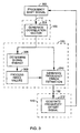
- a frequency shifted signal 112 is generated in a step 302, by rotator 110 , and input to FHT correlator 120 .
- a correlation vector generator portion of FHT correlator 120 generates a correlation vector 122 in a step 304 which is input to discriminator 130.
- discriminator 130 determines the signal energy in a step 306 corresponding to the highest energy correlator output. The index of this output is used to form or generate one or more additional Walsh function indices, in a step 308, that are related to the highest energy correlator output index by powers of two.
- Indices are formed in step 308 by inverting one or more bits of the binary representation of the highest energy index. These indices are used to estimate the frequency error in a step 310, to produce frequency error signal 132 (ê ).
- the indices indicate the output values (vector components) to be used to generate the error estimate from the correlator output (vector). That is, the outputs to use in computing cross products.
- the Walsh index values used by discriminator 130 may be obtained employing various processing techniques, as disclosed herein.
- the estimate of the frequency error from step 310 is the referred to as the "current error” for the tracking loop.
- the frequency error estimate can subsequently be used in a step 312 by filter 140 to form frequency offset estimate signal 142 (f and) which is known as the "residual error”.
- Frequency offset estimate signal 142 is then used to adjust the shifting or rotation for input signals by rotator 110.
- the filtering means accumulates the resulting frequency error signals to produce the frequency offset estimate used by the rotator means ("residual error").
- FIG. 3 represents only one possible arrangement of the functional portions of the method used to determine the current error. Alternative arrangements will be apparent to one skilled in the art.
- discriminator 130 may employ various techniques to determine the current error of frequency tracking loop 101. In addition to the techniques employed in the embodiment described above, many other techniques are possible. The choice of which technique to employ is generally guided by the performance characteristics of the frequency tracking loop that are desired. In this regard, the performance of a frequency tracking loop is generally expressed in terms of either (or both) of two characteristics: (1) the steady-state performance of the loop; and (2) the pull-in range of the loop.
- the steady-state performance of a frequency tracking loop is defined as the standard deviation of the steady-state error of the loop.
- the steady-state performance factor indicates how well the loop tracks these drifts (assuming the loop had previously locked onto the carrier frequency).
- the pull-in range of a frequency tracking loop is defined as the range of frequencies over which the loop can differ initially from the carrier frequency and still thereafter settle in on the carrier frequency.
- a loop with a relatively wide pull-in range can accommodate greater differences between loop and carrier frequency.
- the steady-state performance and/or pull-in range of the frequency tracking loop 101 can be varied as desired. For example, when discriminator 130 determines the current error 132 using only the Walsh index obtained by inverting the most significant bit (MSB) of the estimated correct Walsh index, the frequency tracking loop 101 generally has the best steady-state performance. In this case, however, frequency tracking loop 101 also has the smallest pull-in range.
- MSB most significant bit
- discriminator 130 can invert various mid-order bits (e.g., MSB-1, MSB-2, etc.) to achieve intermediate performance characteristics. Still further, discriminator 130 can employ various averaging schemes to estimate the current error. For example, discriminator 130 can determine the current error using an average of the estimates obtained by inverting more than one bit of the correct Walsh index. Based on the disclosure contained herein, combinations in addition to those described above will be readily apparent to one skilled in the art.
- mid-order bits e.g., MSB-1, MSB-2, etc.
- discriminator 130 can employ various averaging schemes to estimate the current error. For example, discriminator 130 can determine the current error using an average of the estimates obtained by inverting more than one bit of the correct Walsh index.
Landscapes
- Engineering & Computer Science (AREA)
- Computer Networks & Wireless Communication (AREA)
- Signal Processing (AREA)
- Mobile Radio Communication Systems (AREA)
- Compression, Expansion, Code Conversion, And Decoders (AREA)
- Reduction Or Emphasis Of Bandwidth Of Signals (AREA)
- Digital Transmission Methods That Use Modulated Carrier Waves (AREA)
- Stabilization Of Oscillater, Synchronisation, Frequency Synthesizers (AREA)
Applications Claiming Priority (3)
| Application Number | Priority Date | Filing Date | Title |
|---|---|---|---|
| US625481 | 1996-03-29 | ||
| US08/625,481 US6330291B1 (en) | 1996-03-29 | 1996-03-29 | Frequency tracking for communication signals using M-ary orthogonal walsh modulation |
| PCT/US1997/006379 WO1997037437A1 (en) | 1996-03-29 | 1997-03-26 | Frequency tracking for communication signals using m-ary orthogonal walsh modulation |
Publications (2)
| Publication Number | Publication Date |
|---|---|
| EP0829146A1 EP0829146A1 (en) | 1998-03-18 |
| EP0829146B1 true EP0829146B1 (en) | 2005-03-02 |
Family
ID=24506294
Family Applications (1)
| Application Number | Title | Priority Date | Filing Date |
|---|---|---|---|
| EP97918684A Expired - Lifetime EP0829146B1 (en) | 1996-03-29 | 1997-03-26 | Frequency tracking for communication signals using m-ary orthogonal walsh modulation |
Country Status (12)
| Country | Link |
|---|---|
| US (1) | US6330291B1 (enExample) |
| EP (1) | EP0829146B1 (enExample) |
| JP (1) | JP3860213B2 (enExample) |
| KR (1) | KR100470000B1 (enExample) |
| CN (1) | CN1168229C (enExample) |
| AT (1) | ATE290269T1 (enExample) |
| AU (1) | AU727941B2 (enExample) |
| BR (1) | BR9702149B1 (enExample) |
| CA (1) | CA2222644C (enExample) |
| DE (1) | DE69732595T2 (enExample) |
| RU (1) | RU2234197C2 (enExample) |
| WO (1) | WO1997037437A1 (enExample) |
Families Citing this family (21)
| Publication number | Priority date | Publication date | Assignee | Title |
|---|---|---|---|---|
| US6134260A (en) * | 1997-12-16 | 2000-10-17 | Ericsson Inc. | Method and apparatus for frequency acquisition and tracking for DS-SS CDMA receivers |
| US6678310B1 (en) * | 1998-01-16 | 2004-01-13 | Intersil Americas Inc | Wireless local area network spread spectrum transceiver with multipath mitigation |
| DE19846870C1 (de) * | 1998-10-12 | 2001-01-25 | Peter Peyerl | Verfahren zur Bestimmung der Impulsantwort eines breitbandigen linearen Systems und Meßanordnung zur Durchführung des Verfahrens |
| FR2795257A1 (fr) * | 1999-06-15 | 2000-12-22 | Koninkl Philips Electronics Nv | Detecteur de phase pour systeme de transmission a etalement de spectre |
| US6977974B1 (en) * | 2000-11-20 | 2005-12-20 | At&T Corp. | De-modulation of MOK(M-ary orthogonal modulation) |
| US8385470B2 (en) * | 2000-12-05 | 2013-02-26 | Google Inc. | Coding a signal with a shuffled-Hadamard function |
| US8374218B2 (en) * | 2000-12-05 | 2013-02-12 | Google Inc. | Combining signals with a shuffled-hadamard function |
| JP4572482B2 (ja) * | 2001-04-11 | 2010-11-04 | 株式会社デンソー | Cdma方式の無線通信機の復調装置 |
| FI110725B (fi) | 2001-04-20 | 2003-03-14 | Nokia Corp | Menetelmä vastaanottimen tahdistamisessa ja vastaanotin |
| US6552996B2 (en) * | 2001-09-18 | 2003-04-22 | Interdigital Communications Corporation | OVSF code system and methods |
| KR100534592B1 (ko) * | 2002-06-20 | 2005-12-07 | 한국전자통신연구원 | 디지털 통신 시스템의 수신 장치 및 그 방법 |
| US6795486B2 (en) * | 2002-09-23 | 2004-09-21 | Thomson Licensing S.A. | Variable-length correlator for spread-spectrum communications |
| US7787357B2 (en) * | 2003-12-18 | 2010-08-31 | Motorola, Inc. | OFDM frequency offset estimation apparatus and method |
| WO2006052156A1 (en) * | 2004-11-12 | 2006-05-18 | Intel Corporation | Method and apparatus to perform equalization and decoding for a communication system |
| US8139685B2 (en) * | 2005-05-10 | 2012-03-20 | Qualcomm Incorporated | Systems, methods, and apparatus for frequency control |
| KR100821938B1 (ko) * | 2006-04-14 | 2008-04-15 | 삼성전자주식회사 | 무선통신시스템에서 상향링크 주파수 옵셋 추정 장치 및방법 |
| KR100947604B1 (ko) * | 2007-12-17 | 2010-03-15 | 한국전자통신연구원 | 이동통신 시스템에서 2차 루프 필터를 사용하는 주파수오차 추정기 및 그 동작방법 |
| US9071493B2 (en) * | 2009-06-29 | 2015-06-30 | Qualcomm Incorporated | Dual frequency tracking loop for OFDMA systems |
| JP5621476B2 (ja) * | 2010-09-29 | 2014-11-12 | ソニー株式会社 | 同期回路、同期方法、および受信システム |
| CN111614373B (zh) * | 2020-05-20 | 2021-08-10 | 北京升哲科技有限公司 | 扩频信号发送、扩频信号接收方法、装置、设备及介质 |
| CN114389640B (zh) * | 2022-01-17 | 2023-05-30 | 深圳华海尖兵科技有限公司 | 复杂信号条件下的调制及解调方法、装置及电子设备 |
Family Cites Families (11)
| Publication number | Priority date | Publication date | Assignee | Title |
|---|---|---|---|---|
| US4494238A (en) * | 1982-06-30 | 1985-01-15 | Motorola, Inc. | Multiple channel data link system |
| US4841544A (en) | 1987-05-14 | 1989-06-20 | The Charles Stark Draper Laboratory, Inc. | Digital direct sequence spread spectrum receiver |
| NZ232223A (en) * | 1989-01-27 | 1993-03-26 | British Telecomm | Alternate burst communication for cordless phones re-established after channel failure |
| IL100213A (en) * | 1990-12-07 | 1995-03-30 | Qualcomm Inc | CDMA microcellular telephone system and distributed antenna system therefor |
| US5357454A (en) | 1991-07-25 | 1994-10-18 | Ericsson Ge Mobile Communications Holding, Inc. | Fast walsh transform processor |
| US5687166A (en) * | 1992-11-24 | 1997-11-11 | Stanford Telecommunications, Inc. | Modulation system for spread spectrum CDMA communication |
| US5822318A (en) * | 1994-07-29 | 1998-10-13 | Qualcomm Incorporated | Method and apparatus for controlling power in a variable rate communication system |
| US5619524A (en) * | 1994-10-04 | 1997-04-08 | Motorola, Inc. | Method and apparatus for coherent communication reception in a spread-spectrum communication system |
| US5608722A (en) * | 1995-04-03 | 1997-03-04 | Qualcomm Incorporated | Multi-user communication system architecture with distributed receivers |
| US5623487A (en) * | 1995-05-19 | 1997-04-22 | Stanford Telecommunications, Inc. | Doubly orthogonal code and frequency division multiple access communication system |
| US5764630A (en) * | 1996-03-25 | 1998-06-09 | Stanford Telecommunications, Inc. | Forward link carrier recovery in an OCDMA spread spectrum communication system without a pilot tone |
-
1996
- 1996-03-29 US US08/625,481 patent/US6330291B1/en not_active Expired - Lifetime
-
1997
- 1997-03-26 AT AT97918684T patent/ATE290269T1/de not_active IP Right Cessation
- 1997-03-26 JP JP53563897A patent/JP3860213B2/ja not_active Expired - Fee Related
- 1997-03-26 DE DE69732595T patent/DE69732595T2/de not_active Expired - Lifetime
- 1997-03-26 RU RU97121858/09A patent/RU2234197C2/ru not_active IP Right Cessation
- 1997-03-26 BR BRPI9702149-0A patent/BR9702149B1/pt not_active IP Right Cessation
- 1997-03-26 CN CNB971902690A patent/CN1168229C/zh not_active Expired - Fee Related
- 1997-03-26 CA CA002222644A patent/CA2222644C/en not_active Expired - Fee Related
- 1997-03-26 EP EP97918684A patent/EP0829146B1/en not_active Expired - Lifetime
- 1997-03-26 KR KR1019970708627A patent/KR100470000B1/ko not_active Expired - Fee Related
- 1997-03-26 AU AU26731/97A patent/AU727941B2/en not_active Ceased
- 1997-03-26 WO PCT/US1997/006379 patent/WO1997037437A1/en not_active Ceased
Also Published As
| Publication number | Publication date |
|---|---|
| BR9702149A (pt) | 1999-07-20 |
| HK1010957A1 (en) | 1999-07-02 |
| BR9702149B1 (pt) | 2011-03-09 |
| DE69732595D1 (de) | 2005-04-07 |
| RU2234197C2 (ru) | 2004-08-10 |
| CA2222644C (en) | 2005-06-28 |
| JP3860213B2 (ja) | 2006-12-20 |
| WO1997037437A1 (en) | 1997-10-09 |
| EP0829146A1 (en) | 1998-03-18 |
| CN1168229C (zh) | 2004-09-22 |
| AU2673197A (en) | 1997-10-22 |
| CN1185873A (zh) | 1998-06-24 |
| KR19990022148A (ko) | 1999-03-25 |
| CA2222644A1 (en) | 1997-10-09 |
| JPH11506598A (ja) | 1999-06-08 |
| KR100470000B1 (ko) | 2005-03-16 |
| ATE290269T1 (de) | 2005-03-15 |
| US6330291B1 (en) | 2001-12-11 |
| AU727941B2 (en) | 2001-01-04 |
| DE69732595T2 (de) | 2006-01-12 |
Similar Documents
| Publication | Publication Date | Title |
|---|---|---|
| EP0829146B1 (en) | Frequency tracking for communication signals using m-ary orthogonal walsh modulation | |
| US6614864B1 (en) | Apparatus for and method of adaptive synchronization in a spread spectrum communications receiver | |
| US7787355B2 (en) | M-ary orthogonal keying system | |
| US5488629A (en) | Signal processing circuit for spread spectrum communications | |
| US7957256B2 (en) | M-ary orthogonal keying system | |
| US5463657A (en) | Detection of a multi-sequence spread spectrum signal | |
| US5253268A (en) | Method and apparatus for the correlation of sample bits of spread spectrum radio signals | |
| US6128331A (en) | Correlation system for use in wireless direct sequence spread spectrum systems | |
| EP1040593B1 (en) | Method and apparatus for frequency acquisition and tracking for ds-ss cdma receivers | |
| JP3695316B2 (ja) | スペクトラム拡散受信機の相関検出器 | |
| US7366227B2 (en) | Chip-to-symbol receiver despreader architectures and methods for despreading spread spectrum signals | |
| US6570842B1 (en) | System and apparatus for designing and producing signalling waveforms for direct-sequence code division multiple access communications | |
| CA2495414C (en) | Frequency tracking for communications signals using m-ary orthogonal walsh modulation | |
| HK1010957B (en) | Frequency tracking for communication signals using m-ary orthogonal walsh modulation | |
| JP3179554B2 (ja) | スペクトラム拡散通信システム | |
| EP1148656B1 (en) | Method and apparatus for synchronisation in a wireless communications system | |
| JP3282160B2 (ja) | スペクトル拡散送受信機 |
Legal Events
| Date | Code | Title | Description |
|---|---|---|---|
| PUAI | Public reference made under article 153(3) epc to a published international application that has entered the european phase |
Free format text: ORIGINAL CODE: 0009012 |
|
| 17P | Request for examination filed |
Effective date: 19971124 |
|
| AK | Designated contracting states |
Kind code of ref document: A1 Designated state(s): AT BE CH DE DK ES FI FR GB GR IE IT LI LU MC NL PT SE |
|
| AX | Request for extension of the european patent |
Free format text: AL PAYMENT 971124;LT PAYMENT 971124;LV PAYMENT 971124;RO PAYMENT 971124;SI PAYMENT 971124 |
|
| RAP1 | Party data changed (applicant data changed or rights of an application transferred) |
Owner name: QUALCOMM INCORPORATED |
|
| 17Q | First examination report despatched |
Effective date: 20030204 |
|
| GRAP | Despatch of communication of intention to grant a patent |
Free format text: ORIGINAL CODE: EPIDOSNIGR1 |
|
| GRAS | Grant fee paid |
Free format text: ORIGINAL CODE: EPIDOSNIGR3 |
|
| GRAA | (expected) grant |
Free format text: ORIGINAL CODE: 0009210 |
|
| AK | Designated contracting states |
Kind code of ref document: B1 Designated state(s): AT BE CH DE DK ES FI FR GB GR IE IT LI LU MC NL PT SE |
|
| AX | Request for extension of the european patent |
Extension state: AL LT LV RO SI |
|
| PG25 | Lapsed in a contracting state [announced via postgrant information from national office to epo] |
Ref country code: NL Free format text: LAPSE BECAUSE OF FAILURE TO SUBMIT A TRANSLATION OF THE DESCRIPTION OR TO PAY THE FEE WITHIN THE PRESCRIBED TIME-LIMIT Effective date: 20050302 Ref country code: LI Free format text: LAPSE BECAUSE OF FAILURE TO SUBMIT A TRANSLATION OF THE DESCRIPTION OR TO PAY THE FEE WITHIN THE PRESCRIBED TIME-LIMIT Effective date: 20050302 Ref country code: CH Free format text: LAPSE BECAUSE OF FAILURE TO SUBMIT A TRANSLATION OF THE DESCRIPTION OR TO PAY THE FEE WITHIN THE PRESCRIBED TIME-LIMIT Effective date: 20050302 Ref country code: BE Free format text: LAPSE BECAUSE OF FAILURE TO SUBMIT A TRANSLATION OF THE DESCRIPTION OR TO PAY THE FEE WITHIN THE PRESCRIBED TIME-LIMIT Effective date: 20050302 Ref country code: AT Free format text: LAPSE BECAUSE OF FAILURE TO SUBMIT A TRANSLATION OF THE DESCRIPTION OR TO PAY THE FEE WITHIN THE PRESCRIBED TIME-LIMIT Effective date: 20050302 |
|
| REG | Reference to a national code |
Ref country code: GB Ref legal event code: FG4D |
|
| REG | Reference to a national code |
Ref country code: CH Ref legal event code: EP |
|
| PG25 | Lapsed in a contracting state [announced via postgrant information from national office to epo] |
Ref country code: LU Free format text: LAPSE BECAUSE OF NON-PAYMENT OF DUE FEES Effective date: 20050326 |
|
| PG25 | Lapsed in a contracting state [announced via postgrant information from national office to epo] |
Ref country code: MC Free format text: LAPSE BECAUSE OF NON-PAYMENT OF DUE FEES Effective date: 20050331 |
|
| REG | Reference to a national code |
Ref country code: IE Ref legal event code: FG4D |
|
| REF | Corresponds to: |
Ref document number: 69732595 Country of ref document: DE Date of ref document: 20050407 Kind code of ref document: P |
|
| REG | Reference to a national code |
Ref country code: HK Ref legal event code: GR Ref document number: 1010957 Country of ref document: HK |
|
| REG | Reference to a national code |
Ref country code: SE Ref legal event code: TRGR |
|
| PG25 | Lapsed in a contracting state [announced via postgrant information from national office to epo] |
Ref country code: GR Free format text: LAPSE BECAUSE OF FAILURE TO SUBMIT A TRANSLATION OF THE DESCRIPTION OR TO PAY THE FEE WITHIN THE PRESCRIBED TIME-LIMIT Effective date: 20050602 Ref country code: DK Free format text: LAPSE BECAUSE OF FAILURE TO SUBMIT A TRANSLATION OF THE DESCRIPTION OR TO PAY THE FEE WITHIN THE PRESCRIBED TIME-LIMIT Effective date: 20050602 |
|
| PG25 | Lapsed in a contracting state [announced via postgrant information from national office to epo] |
Ref country code: ES Free format text: LAPSE BECAUSE OF FAILURE TO SUBMIT A TRANSLATION OF THE DESCRIPTION OR TO PAY THE FEE WITHIN THE PRESCRIBED TIME-LIMIT Effective date: 20050613 |
|
| PG25 | Lapsed in a contracting state [announced via postgrant information from national office to epo] |
Ref country code: PT Free format text: LAPSE BECAUSE OF FAILURE TO SUBMIT A TRANSLATION OF THE DESCRIPTION OR TO PAY THE FEE WITHIN THE PRESCRIBED TIME-LIMIT Effective date: 20050817 |
|
| LTIE | Lt: invalidation of european patent or patent extension |
Effective date: 20050302 |
|
| NLV1 | Nl: lapsed or annulled due to failure to fulfill the requirements of art. 29p and 29m of the patents act | ||
| REG | Reference to a national code |
Ref country code: CH Ref legal event code: PL |
|
| PLBE | No opposition filed within time limit |
Free format text: ORIGINAL CODE: 0009261 |
|
| STAA | Information on the status of an ep patent application or granted ep patent |
Free format text: STATUS: NO OPPOSITION FILED WITHIN TIME LIMIT |
|
| 26N | No opposition filed |
Effective date: 20051205 |
|
| ET | Fr: translation filed | ||
| PGFP | Annual fee paid to national office [announced via postgrant information from national office to epo] |
Ref country code: SE Payment date: 20091223 Year of fee payment: 14 |
|
| PGFP | Annual fee paid to national office [announced via postgrant information from national office to epo] |
Ref country code: IE Payment date: 20100114 Year of fee payment: 14 |
|
| PGFP | Annual fee paid to national office [announced via postgrant information from national office to epo] |
Ref country code: IT Payment date: 20100320 Year of fee payment: 14 Ref country code: FR Payment date: 20100318 Year of fee payment: 14 Ref country code: FI Payment date: 20100301 Year of fee payment: 14 |
|
| PGFP | Annual fee paid to national office [announced via postgrant information from national office to epo] |
Ref country code: GB Payment date: 20100208 Year of fee payment: 14 |
|
| PGFP | Annual fee paid to national office [announced via postgrant information from national office to epo] |
Ref country code: DE Payment date: 20100331 Year of fee payment: 14 |
|
| REG | Reference to a national code |
Ref country code: SE Ref legal event code: EUG |
|
| GBPC | Gb: european patent ceased through non-payment of renewal fee |
Effective date: 20110326 |
|
| PG25 | Lapsed in a contracting state [announced via postgrant information from national office to epo] |
Ref country code: FI Free format text: LAPSE BECAUSE OF NON-PAYMENT OF DUE FEES Effective date: 20110326 |
|
| REG | Reference to a national code |
Ref country code: FR Ref legal event code: ST Effective date: 20111130 |
|
| REG | Reference to a national code |
Ref country code: IE Ref legal event code: MM4A |
|
| PG25 | Lapsed in a contracting state [announced via postgrant information from national office to epo] |
Ref country code: DE Free format text: LAPSE BECAUSE OF NON-PAYMENT OF DUE FEES Effective date: 20111001 Ref country code: FR Free format text: LAPSE BECAUSE OF NON-PAYMENT OF DUE FEES Effective date: 20110331 Ref country code: IE Free format text: LAPSE BECAUSE OF NON-PAYMENT OF DUE FEES Effective date: 20110328 |
|
| REG | Reference to a national code |
Ref country code: DE Ref legal event code: R119 Ref document number: 69732595 Country of ref document: DE Effective date: 20111001 |
|
| PG25 | Lapsed in a contracting state [announced via postgrant information from national office to epo] |
Ref country code: GB Free format text: LAPSE BECAUSE OF NON-PAYMENT OF DUE FEES Effective date: 20110326 Ref country code: IT Free format text: LAPSE BECAUSE OF NON-PAYMENT OF DUE FEES Effective date: 20110326 |
|
| PG25 | Lapsed in a contracting state [announced via postgrant information from national office to epo] |
Ref country code: SE Free format text: LAPSE BECAUSE OF NON-PAYMENT OF DUE FEES Effective date: 20110327 |