EP0828322A2 - Verbinder mit Führungsbuchse mit innerer Befestigung - Google Patents
Verbinder mit Führungsbuchse mit innerer Befestigung Download PDFInfo
- Publication number
- EP0828322A2 EP0828322A2 EP97115232A EP97115232A EP0828322A2 EP 0828322 A2 EP0828322 A2 EP 0828322A2 EP 97115232 A EP97115232 A EP 97115232A EP 97115232 A EP97115232 A EP 97115232A EP 0828322 A2 EP0828322 A2 EP 0828322A2
- Authority
- EP
- European Patent Office
- Prior art keywords
- guide bush
- bore
- accordance
- front face
- electrical connector
- Prior art date
- Legal status (The legal status is an assumption and is not a legal conclusion. Google has not performed a legal analysis and makes no representation as to the accuracy of the status listed.)
- Withdrawn
Links
Images


Classifications
-
- H—ELECTRICITY
- H01—ELECTRIC ELEMENTS
- H01R—ELECTRICALLY-CONDUCTIVE CONNECTIONS; STRUCTURAL ASSOCIATIONS OF A PLURALITY OF MUTUALLY-INSULATED ELECTRICAL CONNECTING ELEMENTS; COUPLING DEVICES; CURRENT COLLECTORS
- H01R12/00—Structural associations of a plurality of mutually-insulated electrical connecting elements, specially adapted for printed circuits, e.g. printed circuit boards [PCB], flat or ribbon cables, or like generally planar structures, e.g. terminal strips, terminal blocks; Coupling devices specially adapted for printed circuits, flat or ribbon cables, or like generally planar structures; Terminals specially adapted for contact with, or insertion into, printed circuits, flat or ribbon cables, or like generally planar structures
- H01R12/70—Coupling devices
- H01R12/7005—Guiding, mounting, polarizing or locking means; Extractors
-
- H—ELECTRICITY
- H01—ELECTRIC ELEMENTS
- H01R—ELECTRICALLY-CONDUCTIVE CONNECTIONS; STRUCTURAL ASSOCIATIONS OF A PLURALITY OF MUTUALLY-INSULATED ELECTRICAL CONNECTING ELEMENTS; COUPLING DEVICES; CURRENT COLLECTORS
- H01R12/00—Structural associations of a plurality of mutually-insulated electrical connecting elements, specially adapted for printed circuits, e.g. printed circuit boards [PCB], flat or ribbon cables, or like generally planar structures, e.g. terminal strips, terminal blocks; Coupling devices specially adapted for printed circuits, flat or ribbon cables, or like generally planar structures; Terminals specially adapted for contact with, or insertion into, printed circuits, flat or ribbon cables, or like generally planar structures
- H01R12/70—Coupling devices
- H01R12/71—Coupling devices for rigid printing circuits or like structures
- H01R12/712—Coupling devices for rigid printing circuits or like structures co-operating with the surface of the printed circuit or with a coupling device exclusively provided on the surface of the printed circuit
- H01R12/716—Coupling device provided on the PCB
Definitions
- the present invention relates to electrical connectors and, more particularly, electrical connectors including mounting hardware or guide bushes.
- a typical electrical connector of the input/output type comprises an insulative housing having a front face and a mating portion projecting forwardly from the front face, a plurality of terminals mounted in the housing, the terminals generally having contact portions disposed along the mating portion, and a conductive shield on the front face of the housing, the shield generally including a shroud encircling the mating portion and a flange integrally formed with the shroud for overlying at least a portion of the front face of the connector.
- an internally threaded cylindrical recess extends through the flange and front face on either side of the shroud to provide a pair of recesses into which externally threaded guide bushes may be mounted.
- guide bushes have a relatively narrow externally threaded tail section for spirally engaging the internally threaded recesses, as well as a relatively wider polygonal head section for mounting adjacent the front face and projecting forwardly from the front face to provide a tapered guide pin-receiving aperture and axial cylindrical bore for enhancing mating capability with a corresponding electrical connector or electronic device.
- Guide bushes typically include a hexagonal outside surface which is engaged by a rotating tool to mount the guide bush into internally threaded recesses of the electrical connector.
- the rotating tool typically includes some type of nut driving socket or other type of wrench-like device.
- the recesses that receive the guide bushes must be disposed sufficiently far from the shroud.
- U.S. Patent No. 5,340,329 discloses an electrical connector having latch hardware that includes a cylindrical body and a screw head shaped tip. This structure does not, however, function in the same manner as a guide bush of the present invention.
- an electrical connector having at least one guide bush for mounting upon a front face of the electrical connector into an appropriately configured, internally threaded recess in the front face, the guide bush for receiving therein a guide pin from a mating electronic component, the guide bush comprising an integral, generally cylindrical body having a head portion of a first width and an externally threaded tail portion of a second width smaller than the first width, the generally cylindrical body having a coaxial bore substantially therethrough, the bore having an engageable portion for engaging with a correspondingly shaped insertable jig, whereby the jig may be inserted into the bore for rotatingly engaging the engageable portion thereof and rotatingly mounting the guide bush onto the front face by rotating the externally threaded tail portion of the guide bush into the internally threaded recess in the front face.
- a guide bush for use with the described electrical connector and a connector having a structure appropriate for use with the new guide bush.
- the guide bush is for mounting upon a front face of the electrical connector into an appropriately configured, internally threaded recess in the front face, the guide bush for receiving therein a guide pin from a mating electronic component, the guide bush comprising an integral, generally cylindrical body having a head portion of a first width and an externally threaded tail portion of a second width smaller than the first width, the generally cylindrical body having a coaxial bore substantially therethrough, the bore having an engageable portion for engaging with a correspondingly shaped insertable jig, whereby the jig may be inserted into the bore for rotatingly engaging the engageable portion thereof and rotatingly mounting the guide bush onto the front face by rotating the externally threaded tail portion of the guide bush into the internally threaded recess in the front face.
- the connector has an insulative housing having a front face and a mating portion projecting forwardly from the front face, a plurality of terminals mounted in the housing, the terminals having contact portions disposed along the mating portion, and a conductive shield including a shroud generally encircling the mating portion of the housing and a flange integrally formed with the shroud, the flange overlying at least a portion of the front face, the shroud meeting the flange along the base of the shroud.
- a generally cylindrical recess extends through the flange of the shield and the front face at the portion where the flange overlies the front face, the recess configured for receiving therein a guide bush.
- the radius of the generally cylindrical recess at the front face is smaller than the minimum distance between the perimeter of the recess at the front face and the base of the shroud.
- FIGURE 1 is a front elevational view of a broken away portion of a prior art connector.
- FIGURE 2 is a front elevational view of a broken away portion of a connector in accordance with a preferred embodiment of the invention.
- FIGURE 3 is a side elevational view of a guide bush in accordance with a preferred embodiment of the invention.
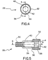
- FIGURE 4 is a front elevational view of a guide bush in accordance with a preferred embodiment of the invention.
- FIGURE 5 is a cross-sectional view of the guide bush of FIGURE 4 taken substantially along the line 5-5, as shown in FIGURE 4.
- FIGURE 6 is a cross-sectional view of the guide bush of FIGURE 4 taken substantially along the line 6-6, as shown in FIGURE 5.
- FIGURE 7 is a front elevational view of a broken away portion of a connector in accordance with a first alternative embodiment of the invention.
- FIGURE 8 is a cross-sectional view of a guide bush in accordance with a first alternative embodiment of the invention.
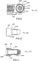
- FIGURE 9 is a front elevational view of a broken away portion of a connector in accordance with a second alternative embodiment of the invention.
- FIGURE 10 is a side elevational view of a guide bush in accordance with a second alternative embodiment of the invention.
- FIGURE 11 is a cross-sectional view of a guide bush in accordance with a second alternative embodiment of the invention.
- FIG. 2 shows a broken away portion of an electrical input/output connector 10 in accordance with the present invention.
- the connector 10 has an insulative housing 12 having a front face 14 and a mating portion 22 projecting forwardly from the front face 14.
- a plurality of terminals are mounted in the housing 12, and the terminals have contact portions 26 disposed along the mating portion 22.
- a conductive shield 16 sits on the front face 14 of the housing 12, the shield 16 including a shroud 18 which generally encircles the mating portion 22 of the housing 12 and a flange 20 integrally formed with the shroud 18 for overlying at least a portion of the front face 14.
- the shield 16 is preferably one-piece, and the shroud 18 meets the flange 20 along the base of the shroud.
- FIGS. 1 and 2 contrast a connector 10 in accordance with the invention (FIG. 2) with a typical prior art connector 60 (FIG. 1).
- the shroud 62 of the prior art connector is generally trapezoidal while the shroud 18 of the inventive connector 10 is substantially rectangular. While the generally rectangular shape is preferable for some applications, it is not a requirement of the invention described herein, and in fact, the invention contemplates a trapezoidal shroud in alternative embodiments thereof.
- the front face of a prior art input/output connector 60 has an internally-threaded guide bush recess on both sides of the shroud 62.
- the flange of the shield may also extend over the recesses, but the flange would then have an aperture matching the opening of the recess so as not to cover the recess and prevent mounting of a guide bush therein.
- a guide bush having an externally-threaded tail portion may then be mounted onto the front face of the connector by spirally threading the tail portion into the guide bush recess of the connector.
- the guide bush in addition to having a relatively narrower tail portion for insertion into the recess, also has a relatively wider head portion for coming flush with a panel adjacent the flange portion of the shield overlying the front face of the connector when the guide bush is mounted into the recess.
- the head portion of the guide bush has traditionally had a hexagonal perimeter 68 (as shown in FIG. 1) and a cylindrical bore 66 axially therethrough or mostly therethrough.
- a guide bush is typically mounted to the front face of the connector 60 by using a circumscribing rotating tool, such as a nut driving socket, a box-driver or a wrench.
- the inventive guide bush 28 as shown in FIGS. 2-6, has a relatively narrow, cylindrical, externally-threaded tail portion 30, a relatively wide head portion 32 of generally circular perimeter 38, and an intermediately-sized cylindrical intermediate portion 34 therebetween.
- the guide bush recesses of the inventive connector 10 are stepped so as to accommodate receiving therein cylindrical segments of distinct radii, i.e., both the tail portion 30 and the intermediate portion 34 of the guide bush 28.
- the portion of the recess which accommodates the tail portion 30 is internally threaded so that the guide bush may be rotatably mounted therein.
- the guide bush 28 is fully mounted onto the flange 20 of the shield 16 and front face 14 of the connector 10 when the rear surface 36 of the head portion 32 of the guide bush 28 comes flush to a panel (not shown) against which the flange of the shield 16 is mounted.
- the generally cylindrical bore 40 has a tapered aperture 44 and a hexagonal engagement portion 42 within the head portion of the guide bush 28.
- a correspondingly-shaped insertable jig or tool may be inserted into the bore 40 for rotatingly engaging the hexagonal engaging portion 42 and thereby rotatingly mounting the guide bush 28 onto the flange 20 of the shield 16 which is generally adjacent the front face 14 of the connector 10.
- the guide bush 28 is rotatingly engaged from inside the axial bore 40 rather than being circumscribingly engaged at its perimeter as in the prior art. This manner of engagement removes the necessity for providing as much clearance between the most radially outward point of the head portion of the guide bush and the projecting shroud of the shield.
- FIGS. 7 and 8 A first alternative embodiment of the invention is shown in FIGS. 7 and 8.
- the first alternative embodiment of the connector 110 is shown in Figure 7 to have a guide bush 112 in accordance with the invention.
- the guide bush includes a relatively narrow, externally threaded tail portion 114 and relatively wider generally cylindrical head portion 116.
- the first alternative embodiment lacks an intermediate portion and a correspondingly stepped recess in the housing.
- the first alternative embodiment of the guide bush 112 has a substantially circular perimeter 120 of the head portion 116.
- a coaxial bore 122 extends substantially through the length of the guide bush 112, and a tapered opening 126 to the bore facilitates its engagement with a guide pin from a mating electronic component.
- Engagement portion 124 is engageable with a correspondingly shaped insertable jig or tool, whereby the jig may be inserted into the bore for rotatingly engaging the engageable portion 124 and rotatingly mounting the guide bush 112 onto the connector by rotating the externally threaded tail portion 114 of the guide bush 112 into the internally threaded recess of the connector 110.
- FIGS. 9-11 A second alternative embodiment of the invention is shown in FIGS. 9-11.
- the connector 210 has an inventive guide bush 212, as shown in FIG. 9.
- the guide bush 212 has a relatively narrow, externally threaded tail portion 214 and a relatively wider, generally cylindrical head portion 216.
- the second alternative embodiment does not have an intermediate portion or corresponding stepped recesses for retaining the guide bushes 212.
- the second alternative embodiment of the guide bush has a generally cylindrical head portion 216 having a rear surface 218 which comes flush with a panel against which the flange of the front face of the connector abuts when the guide bush 212 is fully mounted onto the connector 210.
- the guide bush 212 has a generally cylindrical bore 222 most of the way axially therethrough.
- a cross-shaped or Phillips-tipped engagement portion 224 is engaged by a correspondingly shaped insertable jig or tool whereby the jig rotatingly engages the engagement portion 224 to rotatingly mount the guide bush onto the connector by rotating the externally threaded tail portion 214 of the guide bush 212 into the internally threaded recess of the connector 210.
- the cross-shaped or Phillips-tipped engagement portion 224 of Figure 9-11 is replaced with a hexagonal shape such as that shown in Figures 7 and 8.
- the end or bottom of the bore 222 is closed and has a hexagonal shape rather than the cross-shaped or Phillips-tipped engagement portion 224 of Figures 9-11.
- inventive connector and guide bush provide significant advantages over previous input/output connectors.
- inventive connector and guide bush provide a smaller, space-efficient input/output interconnection between electrical components.
- inventive connector requires less distance between the perimeter of the recess and the base of the shroud than the radius of the recess itself at the front face of the connector. This geometric spacing on the front face of the connector provides for an extremely compact and space-efficient connector.
- the minimum distance between the perimeter of the recess at the front face and the base of the shroud is no greater than one-sixteenth of an inch.
- the invention contemplates a multitude of embodiments, such as ones wherein the guide bushes are mounted on the flange and front face of the connector by internally or inscribingly engaging the coaxial bore thereof rather than by externally or circumscribingly engaging the perimeter of the guide bush.
- a more compact shape for the perimeter of the guide bush may be chosen and smaller clearance is required between the outermost point of the guide bush and the most proximate point of the shroud.
- the invention provides a novel electrical connector, and the invention is not limited to the embodiments described herein.
- Specific examples of alternative embodiments considered to be within the scope of the invention include embodiments where the internally engageable portion is proximate to the tapered aperture of the bore in the guide bush and where the engagement portion is disposed in the remote end of the bore from the aperture.
- the invention contemplates the use of differently shaped engageable portions, such as polygonal shapes other than hexagons, or any other suitable shape for rotating engagement. Other modifications to the preferred embodiments may also be made within the scope of the invention.
- the invention is defined by the following claims.
Landscapes
- Details Of Connecting Devices For Male And Female Coupling (AREA)
- Coupling Device And Connection With Printed Circuit (AREA)
Applications Claiming Priority (8)
| Application Number | Priority Date | Filing Date | Title |
|---|---|---|---|
| JP9772/96 | 1996-09-06 | ||
| JP1996009773U JP3035518U (ja) | 1996-09-06 | 1996-09-06 | ガイドブッシュ付き電気コネクタ |
| JP9773/96 | 1996-09-06 | ||
| JP9772/96U | 1996-09-06 | ||
| JP9773/96U | 1996-09-06 | ||
| JP1996009772U JP3035517U (ja) | 1996-09-06 | 1996-09-06 | ガイドブッシュ付き電気コネクタ |
| JP9063755A JPH10255913A (ja) | 1997-03-03 | 1997-03-03 | ガイドブッシュ付き電気コネクタ |
| JP63755/97 | 1997-03-03 |
Publications (2)
| Publication Number | Publication Date |
|---|---|
| EP0828322A2 true EP0828322A2 (de) | 1998-03-11 |
| EP0828322A3 EP0828322A3 (de) | 1999-01-07 |
Family
ID=27278632
Family Applications (1)
| Application Number | Title | Priority Date | Filing Date |
|---|---|---|---|
| EP97115232A Withdrawn EP0828322A3 (de) | 1996-09-06 | 1997-09-03 | Verbinder mit Führungsbuchse mit innerer Befestigung |
Country Status (3)
| Country | Link |
|---|---|
| EP (1) | EP0828322A3 (de) |
| KR (1) | KR100278589B1 (de) |
| CN (1) | CN1104758C (de) |
Cited By (1)
| Publication number | Priority date | Publication date | Assignee | Title |
|---|---|---|---|---|
| CN104300302A (zh) * | 2013-12-05 | 2015-01-21 | 中航光电科技股份有限公司 | 一种直插连接器组件及其插头和插座 |
Family Cites Families (4)
| Publication number | Priority date | Publication date | Assignee | Title |
|---|---|---|---|---|
| GB2076492B (en) * | 1980-03-07 | 1984-02-15 | Rex Michael Graham | Externally threaded conduit bush |
| US5340329A (en) * | 1992-02-28 | 1994-08-23 | Honda Tsushin Kogyo Kabushiki Kaisha | Connector combination |
| JP2900102B2 (ja) * | 1992-10-06 | 1999-06-02 | モレックス インコーポレーテッド | 電気コネクタに於けるガイド部材 |
| EP0720254A2 (de) * | 1994-12-27 | 1996-07-03 | International Business Machines Corporation | Selbstausrichtender Verbinder für eine flexible Schaltung |
-
1997
- 1997-09-03 EP EP97115232A patent/EP0828322A3/de not_active Withdrawn
- 1997-09-05 KR KR1019970045926A patent/KR100278589B1/ko not_active Expired - Fee Related
- 1997-09-06 CN CN97120641A patent/CN1104758C/zh not_active Expired - Fee Related
Cited By (1)
| Publication number | Priority date | Publication date | Assignee | Title |
|---|---|---|---|---|
| CN104300302A (zh) * | 2013-12-05 | 2015-01-21 | 中航光电科技股份有限公司 | 一种直插连接器组件及其插头和插座 |
Also Published As
| Publication number | Publication date |
|---|---|
| CN1184350A (zh) | 1998-06-10 |
| EP0828322A3 (de) | 1999-01-07 |
| CN1104758C (zh) | 2003-04-02 |
| KR19980024364A (ko) | 1998-07-06 |
| KR100278589B1 (ko) | 2001-01-15 |
Similar Documents
| Publication | Publication Date | Title |
|---|---|---|
| US6705894B1 (en) | Shielded electrical connector | |
| US6116942A (en) | Locking device for electrical connector | |
| EP0393864B1 (de) | Elektrischer Verbinder und Befestigungsarm dafür | |
| DE69109410T2 (de) | Mehrpoliger elektrischer Verbinder. | |
| US6116941A (en) | Device for locking two mating connectors | |
| US4715104A (en) | Installation tool | |
| US6257918B1 (en) | Wire harness connector having a contact retention plate | |
| US5921801A (en) | Retention system for electrical connectors | |
| US6494744B1 (en) | Connector assembly | |
| KR100241527B1 (ko) | 볼트 조임형 커넥터 | |
| CN1312890A (zh) | 顶起系紧螺钉 | |
| EP1523071A1 (de) | Verbinderkomponentensystem | |
| JP3435856B2 (ja) | ボールねじ装置 | |
| US6065992A (en) | Guide post of electrical connector | |
| US6428354B1 (en) | Coaxial connector fastening system | |
| US20030171029A1 (en) | Electrical connector | |
| AU620449B2 (en) | Controlled impedance plug and receptacle | |
| US6976303B2 (en) | System and tool for mounting a connecting device to a substrate | |
| US6821140B2 (en) | Electrical cable connector assembly | |
| US6102751A (en) | Female socket assembly for electrical connector | |
| US7029305B2 (en) | Coaxial connector with torque limiting control | |
| US6186839B1 (en) | Electrical connector | |
| EP0863580A2 (de) | Verbinder mit Führungsbuchse mit verbessertem Erdungskontakt | |
| US20050101183A1 (en) | Providing a bracket assembly to attach a device to a system chassis | |
| US5219301A (en) | Keying for a shielded electrical connector |
Legal Events
| Date | Code | Title | Description |
|---|---|---|---|
| PUAI | Public reference made under article 153(3) epc to a published international application that has entered the european phase |
Free format text: ORIGINAL CODE: 0009012 |
|
| AK | Designated contracting states |
Kind code of ref document: A2 Designated state(s): DE FR GB IE IT NL |
|
| AX | Request for extension of the european patent |
Free format text: AL;LT;LV;RO;SI |
|
| PUAL | Search report despatched |
Free format text: ORIGINAL CODE: 0009013 |
|
| AK | Designated contracting states |
Kind code of ref document: A3 Designated state(s): AT BE CH DE DK ES FI FR GB GR IE IT LI LU MC NL PT SE |
|
| AX | Request for extension of the european patent |
Free format text: AL;LT;LV;RO;SI |
|
| 17P | Request for examination filed |
Effective date: 19990614 |
|
| AKX | Designation fees paid |
Free format text: DE FR GB IE IT NL |
|
| STAA | Information on the status of an ep patent application or granted ep patent |
Free format text: STATUS: THE APPLICATION HAS BEEN WITHDRAWN |
|
| 18W | Application withdrawn |
Withdrawal date: 20010605 |