The invention relates to a lamella cutter,
comprising a lower part which bears a lower blade and an
upper part which bears an upper blade and is hingeable with
respect to the lower part about a fixed hinge pin, the
active portion of one of the blades having a shape which
corresponds to the intended shape of the end edge of the
lamella which is to be cut off and the other blade has a
recess which is complementary thereto, while a spring is
present which is active in the sense of opening the two
parts of the cutter, and one of the parts being provided
with guide elements for the lamella, at a spacing which
corresponds to the width of the lamellae for which the
cutter is intended, while finally an adjustable ruler
provided with a raised end face is present as an aid for
fixing the length of the piece which is to be cut off the
lamella.
A lamella cutter of this kind for horizontal
venetian blinds is commercially available in large numbers.
It is disclosed in the following publications:
It appears from these publications that the cutter
originally had no means whatsoever for fixing the length of
the piece which has to be cut off from the lamella. It will
be clear that it is important for all the lamellae to
retain the same length after cutting. The solution which
was subsequently conceived in the form of a ruler with an
endpiece was based on the tenet that the cutter,
essentially having the form which was originally known, was
able to be rotated, and subsequently resiliently moved and
snapped in, with respect to the ruler. The size of the unit
snapped in, with respect to the ruler. The size of the unit
was several times that of the cutter on its own. To the
knowledge of the applicant, this embodiment has never been
used on a large scale.
The object of the present invention is to provide a
lamella cutter such that it contains a stop element or
spacer which does not significantly increase the size of
the cutter, while on the other hand the cost can be kept
low, because the intention, after all, is for these cutters
to be supplied for one-off use with each venetian blind
sold.
The basic principle permits a simple solution if
the cutter has the characteristic that the blades are
positioned parallel to the hinge pin of the two parts and
the guide elements are arranged such that they receive the
lamella between them with its longitudinal direction
perpendicular to the direction of the hinge pin.
As a result, the length of the piece which is to be
cut off now corresponds to the longitudinal direction of
the cutter. In this case, a ruler also extends in this
direction.
A number of variants remain possible within this
basic principle. For example, it is conceivable to make a
ruler which can be slid out on the hinge side in the
longitudinal direction of the cutter. Preferably, however,
the cutter is designed according to the invention such that
the upper part is provided with a feed-through opening for
the lamella, near the hinge pin.
This feed-through opening can be formed by a
U-shaped section of the upper part, the legs of this
U-shape being situated on either side of an elevated
section of the lower part in which the hinge pin is
situated, and the guide elements for the lamella being
arranged on said elevated section.
An extremely simple solution is obtained if the
lower part bears a slide guide for the ruler, with the
direction of sliding perpendicular to the direction of the
hinge pin. A greater longitudinal range for the section
which is to be cut off is obtained, in what is an extremely
simple manner, if the ruler can be slid completely out of
the slide guide and, as a result, can be used in two
positions to extend the range of the length which is to be
cut off.
The range can be increased yet further if an
extension section is displaceable in the slide guide, in
which section the ruler is in turn displaceable.
The invention will be explained below with
reference to the attached drawing of an exemplary embodiment,
in which:
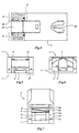
Figs. 2 to 6 show the cutter in the closed
position, specifically
The cutter comprises a lower part 1, an upper part
2 which is hinged with respect to the lower part by means
of hinge pin 3.
The lower part 1 is provided with a slide guide 4,
in which an extension section 5 is displaceable in the
longitudinal direction of the lower part 1, i.e. at right
angles to the direction of the hinge pin 3. The extension
section 5 itself also forms a slide guide, in the same
direction, for a ruler 6, which is provided with a raised
end face 7, designed to have the end of the lamella which
is to be cut off stopped against it when ruler 6, and
possibly extension section 5, have been adjusted to the
desired spacing, as will be explained further.
The lower part 1 has fastened to it the lower blade
8, supported in a manner which will be described in more
detail below. An upper blade, interacting with the lower
blade, is active on the upper part 2, although this is not
yet visible in Fig. 1. The complementary profiles of these
blades may be as in the known blades.
A wire spring 9, which holds the cutter in the open
position of Fig. 1 as long as the upper part 2 is not
manually pressed downwards or a locking mechanism for the
closed position is not activated, is positioned in a base
outside the slide guide 4.
The rear of the upper part 2 is U-shaped, owing to
the presence of an opening 10 through which, in the top
view of Fig. 3, the lower blade 8 can be seen. The legs 11,
11' of the U-shape engage on either side around an elevated
section 12 of the lower part, within which the hinge pin is
situated. Fig. 3 also shows the two guide elements 13 and
13', which have a mutual spacing corresponding to the width
of the lamella for which the cutter is intended, so that
the lamella can be introduced in the direction of the arrow
P, fed through opening 10, above the lower blade 8 until it
is stopped against the raised end face 7 of ruler 6, shown
in Fig. 1.
The bottom view of Fig. 4 shows that the underside
of the lower part 1 is provided with a rectangular recess
14 which runs from the rear edge to approximately halfway
along the length. An integrally-formed piece 15 of the
extension section 5 can be displaced backwards and forwards
in the longitudinal direction in this recess 14. The two
positions of said extension section are determined, on the
one hand, by a snap-in connection which will be described
below, as a result of which it lies level with the rear
edge 16 of the lower part, and, on the other hand, by
resting against the other end of the recess 15. 17 and 17'
show details of the hinge structures, by means of which the
parts 1 and 2 of the cutter are hingeable with respect to
one another.
The rear view of Fig. 5 shows a rear view of the
extension section 5, and the way in which ruler 6 lies
therein.
At the front (Fig. 6), the extension section 5 is
widened to in front of the slide guides 4 (see also Fig.
1). The section of the ruler 6 can also be seen, with the
raised end face 7.
In the open position of the cutter in Fig. 7, a
lamella can be inserted through the opening 10 from the
rear which is then automatically fed over the lower blade 8
which is visible in Fig. 7 and under the upper blade 18
which is visible in this figure. It can already be seen
from Fig. 7 that the upper blade 18 is not arranged
horizontally, but at an angle, so that a cutting action
takes place when the upper part is pressed onto the lower
part.
Fig 8, which depicts a central longitudinal section
in the closed position, shows more details of the mutual
interaction of the blades.
The lower part 2 is provided with a table-shaped
support 19 for the lower blade 8. The cross-sectional shape
of this support 19 can be seen from the cross-section of
Fig. 9. The lower blade 8 lies horizontally, viewed in the
longitudinal direction of the cutter. Viewed from the side,
i.e. along the longitudinal section of Fig. 8, the table is
of a slightly inclined design, so that the lower blade 8
also rests in an inclined manner, with the cutting edge 8'
uppermost, as a result of which a better cutting action is
obtained.
Fig. 8 also shows that the upper part 1 of the
cutter is provided with a blade support 20 which has the
form of a lowered section, which is also visible from the
outside (Fig. 3). Viewed from the side, i.e. in the
longitudinal section of Fig. 8, the upper blade lies
horizontally but viewed in the longitudinal direction,
along the cross-section of Fig. 10, the inclined position
which was also visible in Fig. 7 can be seen again. During
cutting, blade 18 presses against the support 20 and,
moreover, is held clamped in place by two projections, such
as 21, formed integrally on the side walls. Because of this
sloping position of the upper blade 18, a cutting action
will start on the right-hand side, as seen in Fig. 10, and
as the upper part 1 of the cutter is pressed further
downwards will proceed to the left until the entire width
of the lamella situated between the blades has been cut
through.
Returning to Fig. 1, it will be seen that the upper
part 2, near the front end, is provided on the inside with
two studs 22, 22', and that cavities, such as 23, which are
open to the rear are present in the side face of the
extension section. If the extension section 5 is pulled
slightly forwards during closure of the cutter, the upper
part 2 can be moved fully into the closed position on the
lower part 1. If section 5 is then pressed backwards again,
cavities 23 will slide over studs 22, 22' and the cutter is
locked in the closed position. Unlocking can be carried out
by displacing section 5 again slightly, for example by
acting on integrally-formed lowered section 15.
Figs. 8 to 10 offer the possibility of giving
further illustration of some details. Fig. 8 shows the
central longitudinal section of the extension section 5
with the abovementioned, block-shaped lowered section 15,
which is integrally formed thereon, was already shown in a
bottom view in Fig. 4, and which can slide in the recess 14
which is also visible in Fig. 10. Furthermore, extension
section 5 is provided with a snap-in opening 24, in which a
snap-in hook 25 can engage, which forms part of the lower
part 2 of the cutter and which is also visible in Fig. 4.
Fig. 9 again shows the cross-sections of the
extension section 5 and the ruler 6 lying therein. Fig. 10
shows details of how the extension section 5 is enclosed
between the guide elements 4, 4' which are integrally
formed on the lower part 1.
It can be seen in Fig. 1, although not in Fig. 10,
that the ruler 6 is provided on the side faces with snap-in
cavities 26, into which snap-in projections on the inside
of the upright edges of the extension section 5 can snap,
thus forming a number of fixed longitudinal measurements
for the position of ruler 6 with end piece 7 in order to
determine the length of the lamella which is to be cut off.
The position of the snap-in projections and cavities can,
of course, be swapped over. It should also be noted that
the ruler can be slid completely out of the slide guide and
can therefore be used in two positions to extend the range
of the length which is to be cut off.