EP0828056A1 - Scheidvorrichtung für Lamelle - Google Patents
Scheidvorrichtung für Lamelle Download PDFInfo
- Publication number
- EP0828056A1 EP0828056A1 EP96202498A EP96202498A EP0828056A1 EP 0828056 A1 EP0828056 A1 EP 0828056A1 EP 96202498 A EP96202498 A EP 96202498A EP 96202498 A EP96202498 A EP 96202498A EP 0828056 A1 EP0828056 A1 EP 0828056A1
- Authority
- EP
- European Patent Office
- Prior art keywords
- lamella
- cutter
- hinge pin
- ruler
- section
- Prior art date
- Legal status (The legal status is an assumption and is not a legal conclusion. Google has not performed a legal analysis and makes no representation as to the accuracy of the status listed.)
- Withdrawn
Links
Images


Classifications
-
- E—FIXED CONSTRUCTIONS
- E06—DOORS, WINDOWS, SHUTTERS, OR ROLLER BLINDS IN GENERAL; LADDERS
- E06B—FIXED OR MOVABLE CLOSURES FOR OPENINGS IN BUILDINGS, VEHICLES, FENCES OR LIKE ENCLOSURES IN GENERAL, e.g. DOORS, WINDOWS, BLINDS, GATES
- E06B9/00—Screening or protective devices for wall or similar openings, with or without operating or securing mechanisms; Closures of similar construction
- E06B9/24—Screens or other constructions affording protection against light, especially against sunshine; Similar screens for privacy or appearance; Slat blinds
- E06B9/26—Lamellar or like blinds, e.g. venetian blinds
- E06B9/266—Devices or accessories for making or mounting lamellar blinds or parts thereof
-
- B—PERFORMING OPERATIONS; TRANSPORTING
- B26—HAND CUTTING TOOLS; CUTTING; SEVERING
- B26D—CUTTING; DETAILS COMMON TO MACHINES FOR PERFORATING, PUNCHING, CUTTING-OUT, STAMPING-OUT OR SEVERING
- B26D3/00—Cutting work characterised by the nature of the cut made; Apparatus therefor
- B26D3/10—Making cuts of other than simple rectilinear form
Definitions
- the invention relates to a lamella cutter, comprising a lower part which bears a lower blade and an upper part which bears an upper blade and is hingeable with respect to the lower part about a fixed hinge pin, the active portion of one of the blades having a shape which corresponds to the intended shape of the end edge of the lamella which is to be cut off and the other blade has a recess which is complementary thereto, while a spring is present which is active in the sense of opening the two parts of the cutter, and one of the parts being provided with guide elements for the lamella, at a spacing which corresponds to the width of the lamellae for which the cutter is intended, while finally an adjustable ruler provided with a raised end face is present as an aid for fixing the length of the piece which is to be cut off the lamella.
- a lamella cutter of this kind for horizontal venetian blinds is commercially available in large numbers. It is disclosed in the following publications:
- the object of the present invention is to provide a lamella cutter such that it contains a stop element or spacer which does not significantly increase the size of the cutter, while on the other hand the cost can be kept low, because the intention, after all, is for these cutters to be supplied for one-off use with each venetian blind sold.
- the basic principle permits a simple solution if the cutter has the characteristic that the blades are positioned parallel to the hinge pin of the two parts and the guide elements are arranged such that they receive the lamella between them with its longitudinal direction perpendicular to the direction of the hinge pin.
- the length of the piece which is to be cut off now corresponds to the longitudinal direction of the cutter.
- a ruler also extends in this direction.
- the cutter is designed according to the invention such that the upper part is provided with a feed-through opening for the lamella, near the hinge pin.
- This feed-through opening can be formed by a U-shaped section of the upper part, the legs of this U-shape being situated on either side of an elevated section of the lower part in which the hinge pin is situated, and the guide elements for the lamella being arranged on said elevated section.
- the range can be increased yet further if an extension section is displaceable in the slide guide, in which section the ruler is in turn displaceable.
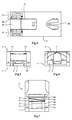
- Figs. 2 to 6 show the cutter in the closed position
- the cutter comprises a lower part 1, an upper part 2 which is hinged with respect to the lower part by means of hinge pin 3.
- the lower part 1 is provided with a slide guide 4, in which an extension section 5 is displaceable in the longitudinal direction of the lower part 1, i.e. at right angles to the direction of the hinge pin 3.
- the extension section 5 itself also forms a slide guide, in the same direction, for a ruler 6, which is provided with a raised end face 7, designed to have the end of the lamella which is to be cut off stopped against it when ruler 6, and possibly extension section 5, have been adjusted to the desired spacing, as will be explained further.
- the lower part 1 has fastened to it the lower blade 8, supported in a manner which will be described in more detail below.
- An upper blade, interacting with the lower blade, is active on the upper part 2, although this is not yet visible in Fig. 1.
- the complementary profiles of these blades may be as in the known blades.
- a wire spring 9 which holds the cutter in the open position of Fig. 1 as long as the upper part 2 is not manually pressed downwards or a locking mechanism for the closed position is not activated, is positioned in a base outside the slide guide 4.
- the rear of the upper part 2 is U-shaped, owing to the presence of an opening 10 through which, in the top view of Fig. 3, the lower blade 8 can be seen.
- the legs 11, 11' of the U-shape engage on either side around an elevated section 12 of the lower part, within which the hinge pin is situated.
- Fig. 3 also shows the two guide elements 13 and 13', which have a mutual spacing corresponding to the width of the lamella for which the cutter is intended, so that the lamella can be introduced in the direction of the arrow P, fed through opening 10, above the lower blade 8 until it is stopped against the raised end face 7 of ruler 6, shown in Fig. 1.
- FIG. 4 shows that the underside of the lower part 1 is provided with a rectangular recess 14 which runs from the rear edge to approximately halfway along the length.
- An integrally-formed piece 15 of the extension section 5 can be displaced backwards and forwards in the longitudinal direction in this recess 14.
- the two positions of said extension section are determined, on the one hand, by a snap-in connection which will be described below, as a result of which it lies level with the rear edge 16 of the lower part, and, on the other hand, by resting against the other end of the recess 15.
- 17 and 17' show details of the hinge structures, by means of which the parts 1 and 2 of the cutter are hingeable with respect to one another.
- FIG. 5 shows a rear view of the extension section 5, and the way in which ruler 6 lies therein.
- the extension section 5 is widened to in front of the slide guides 4 (see also Fig. 1).
- the section of the ruler 6 can also be seen, with the raised end face 7.
- a lamella In the open position of the cutter in Fig. 7, a lamella can be inserted through the opening 10 from the rear which is then automatically fed over the lower blade 8 which is visible in Fig. 7 and under the upper blade 18 which is visible in this figure. It can already be seen from Fig. 7 that the upper blade 18 is not arranged horizontally, but at an angle, so that a cutting action takes place when the upper part is pressed onto the lower part.
- Fig 8 which depicts a central longitudinal section in the closed position, shows more details of the mutual interaction of the blades.
- the lower part 2 is provided with a table-shaped support 19 for the lower blade 8.
- the cross-sectional shape of this support 19 can be seen from the cross-section of Fig. 9.
- the lower blade 8 lies horizontally, viewed in the longitudinal direction of the cutter. Viewed from the side, i.e. along the longitudinal section of Fig. 8, the table is of a slightly inclined design, so that the lower blade 8 also rests in an inclined manner, with the cutting edge 8' uppermost, as a result of which a better cutting action is obtained.
- Fig. 8 also shows that the upper part 1 of the cutter is provided with a blade support 20 which has the form of a lowered section, which is also visible from the outside (Fig. 3).
- the upper blade lies horizontally but viewed in the longitudinal direction, along the cross-section of Fig. 10, the inclined position which was also visible in Fig. 7 can be seen again.
- blade 18 presses against the support 20 and, moreover, is held clamped in place by two projections, such as 21, formed integrally on the side walls. Because of this sloping position of the upper blade 18, a cutting action will start on the right-hand side, as seen in Fig. 10, and as the upper part 1 of the cutter is pressed further downwards will proceed to the left until the entire width of the lamella situated between the blades has been cut through.
- the upper part 2 near the front end, is provided on the inside with two studs 22, 22', and that cavities, such as 23, which are open to the rear are present in the side face of the extension section. If the extension section 5 is pulled slightly forwards during closure of the cutter, the upper part 2 can be moved fully into the closed position on the lower part 1. If section 5 is then pressed backwards again, cavities 23 will slide over studs 22, 22' and the cutter is locked in the closed position. Unlocking can be carried out by displacing section 5 again slightly, for example by acting on integrally-formed lowered section 15.
- Figs. 8 to 10 offer the possibility of giving further illustration of some details.
- Fig. 8 shows the central longitudinal section of the extension section 5 with the abovementioned, block-shaped lowered section 15, which is integrally formed thereon, was already shown in a bottom view in Fig. 4, and which can slide in the recess 14 which is also visible in Fig. 10.
- extension section 5 is provided with a snap-in opening 24, in which a snap-in hook 25 can engage, which forms part of the lower part 2 of the cutter and which is also visible in Fig. 4.
- Fig. 9 again shows the cross-sections of the extension section 5 and the ruler 6 lying therein.
- Fig. 10 shows details of how the extension section 5 is enclosed between the guide elements 4, 4' which are integrally formed on the lower part 1.
- the ruler 6 is provided on the side faces with snap-in cavities 26, into which snap-in projections on the inside of the upright edges of the extension section 5 can snap, thus forming a number of fixed longitudinal measurements for the position of ruler 6 with end piece 7 in order to determine the length of the lamella which is to be cut off.
- the position of the snap-in projections and cavities can, of course, be swapped over.
- the ruler can be slid completely out of the slide guide and can therefore be used in two positions to extend the range of the length which is to be cut off.
Landscapes
- Engineering & Computer Science (AREA)
- Structural Engineering (AREA)
- Life Sciences & Earth Sciences (AREA)
- Forests & Forestry (AREA)
- Mechanical Engineering (AREA)
- Architecture (AREA)
- Civil Engineering (AREA)
- Knives (AREA)
- Details Of Cutting Devices (AREA)
Priority Applications (2)
| Application Number | Priority Date | Filing Date | Title |
|---|---|---|---|
| EP96202498A EP0828056A1 (de) | 1996-09-09 | 1996-09-09 | Scheidvorrichtung für Lamelle |
| TW086112317A TW346432B (en) | 1996-09-09 | 1997-08-27 | Strip lamella cutter |
Applications Claiming Priority (1)
| Application Number | Priority Date | Filing Date | Title |
|---|---|---|---|
| EP96202498A EP0828056A1 (de) | 1996-09-09 | 1996-09-09 | Scheidvorrichtung für Lamelle |
Publications (1)
| Publication Number | Publication Date |
|---|---|
| EP0828056A1 true EP0828056A1 (de) | 1998-03-11 |
Family
ID=8224361
Family Applications (1)
| Application Number | Title | Priority Date | Filing Date |
|---|---|---|---|
| EP96202498A Withdrawn EP0828056A1 (de) | 1996-09-09 | 1996-09-09 | Scheidvorrichtung für Lamelle |
Country Status (2)
| Country | Link |
|---|---|
| EP (1) | EP0828056A1 (de) |
| TW (1) | TW346432B (de) |
Cited By (1)
| Publication number | Priority date | Publication date | Assignee | Title |
|---|---|---|---|---|
| CN102492786A (zh) * | 2011-12-22 | 2012-06-13 | 天津应大股份有限公司 | 一种新型皮绳裁剪装置 |
Citations (5)
| Publication number | Priority date | Publication date | Assignee | Title |
|---|---|---|---|---|
| US4227305A (en) * | 1979-03-12 | 1980-10-14 | Newman Jerry C | Hand tool for cutting blind strips and the like |
| DE8810061U1 (de) * | 1988-08-01 | 1988-09-22 | Teh Yor Industrial Co. Ltd., Taipeh/T'ai-Pei | Schneidwerkzeug, insbesondere für Lamellen vorzugsweise einer Fensterjalousie |
| US4807363A (en) * | 1987-03-05 | 1989-02-28 | Clifton Jr Thomas S | Apparatus for trimming venetian blinds |
| DE9312910U1 (de) * | 1993-08-28 | 1993-10-28 | Teh Yor Industrial Co. Ltd., Taipeh/T'ai-Pei | Kompakter Lamellenabschneider |
| EP0636562A1 (de) * | 1993-06-23 | 1995-02-01 | Brother Kogyo Kabushiki Kaisha | Bandschneidevorrichtung |
-
1996
- 1996-09-09 EP EP96202498A patent/EP0828056A1/de not_active Withdrawn
-
1997
- 1997-08-27 TW TW086112317A patent/TW346432B/zh active
Patent Citations (5)
| Publication number | Priority date | Publication date | Assignee | Title |
|---|---|---|---|---|
| US4227305A (en) * | 1979-03-12 | 1980-10-14 | Newman Jerry C | Hand tool for cutting blind strips and the like |
| US4807363A (en) * | 1987-03-05 | 1989-02-28 | Clifton Jr Thomas S | Apparatus for trimming venetian blinds |
| DE8810061U1 (de) * | 1988-08-01 | 1988-09-22 | Teh Yor Industrial Co. Ltd., Taipeh/T'ai-Pei | Schneidwerkzeug, insbesondere für Lamellen vorzugsweise einer Fensterjalousie |
| EP0636562A1 (de) * | 1993-06-23 | 1995-02-01 | Brother Kogyo Kabushiki Kaisha | Bandschneidevorrichtung |
| DE9312910U1 (de) * | 1993-08-28 | 1993-10-28 | Teh Yor Industrial Co. Ltd., Taipeh/T'ai-Pei | Kompakter Lamellenabschneider |
Cited By (1)
| Publication number | Priority date | Publication date | Assignee | Title |
|---|---|---|---|---|
| CN102492786A (zh) * | 2011-12-22 | 2012-06-13 | 天津应大股份有限公司 | 一种新型皮绳裁剪装置 |
Also Published As
| Publication number | Publication date |
|---|---|
| TW346432B (en) | 1998-12-01 |
Similar Documents
| Publication | Publication Date | Title |
|---|---|---|
| US6079103A (en) | Adjustable attachment comb | |
| US8161857B2 (en) | Blind and shade cutting center for cutting two different window covering products | |
| US4876795A (en) | Cutter, in particular for a slat, especially of a venetian blind | |
| US5598759A (en) | Food slicing rack devices | |
| US5918656A (en) | Retaining clip for sizing a horizontal mini-blind | |
| US6382294B1 (en) | System for holding batteries in a headrail for powered coverings for architectural openings | |
| US5641142A (en) | Ladder tray | |
| US4930218A (en) | Utility knife | |
| HK64694A (en) | Razor head, especially a blade unit of a wet-razor | |
| EP0828056A1 (de) | Scheidvorrichtung für Lamelle | |
| EP1669537A2 (de) | Führungseinrichtung für aufrollbare Stores | |
| US4411066A (en) | Cake cutter | |
| KR100693398B1 (ko) | 안전 커터칼 | |
| DE3716939A1 (de) | Vorrichtung zum schneiden von platten, insbesondere daemmplatten | |
| GB2384501A (en) | Cladding support structure | |
| WO1979000809A1 (en) | A reflection device for roadside marking | |
| EP1988251A2 (de) | Jalousienmontage und Werkzeuge, Komponenten und Verfahren dafür | |
| EP0534038A1 (de) | Verbesserte Schneidvorrichtung für Jalousielamellen | |
| CN217020682U (zh) | 一种挤塑板加工用切边除尘装置 | |
| GB2158221A (en) | Louvred ventilators | |
| US10822740B2 (en) | Portable curtain cutter assembly and method for using thereof | |
| JP4689214B2 (ja) | 角度切り調整機付きテーブルソー | |
| RU2776805C1 (ru) | Насадка-гребень для устройства для срезания волос | |
| CN120418520A (zh) | 用于调整窗覆盖布置结构的尺寸的装置 | |
| EP2886774A1 (de) | Querstrebe für Wandeinbaurahmen zurückziehbarer Schiebetüren |
Legal Events
| Date | Code | Title | Description |
|---|---|---|---|
| PUAI | Public reference made under article 153(3) epc to a published international application that has entered the european phase |
Free format text: ORIGINAL CODE: 0009012 |
|
| AK | Designated contracting states |
Kind code of ref document: A1 Designated state(s): AT BE CH DE DK ES FI FR GB GR IE IT LI LU NL PT SE |
|
| 17P | Request for examination filed |
Effective date: 19980908 |
|
| AKX | Designation fees paid |
Free format text: AT BE CH DE DK ES FI FR GB GR IE IT LI LU NL PT SE |
|
| RBV | Designated contracting states (corrected) |
Designated state(s): AT BE CH DE DK ES FI FR GB GR IE IT LI LU NL PT SE |
|
| 17Q | First examination report despatched |
Effective date: 19980105 |
|
| STAA | Information on the status of an ep patent application or granted ep patent |
Free format text: STATUS: THE APPLICATION IS DEEMED TO BE WITHDRAWN |
|
| 18D | Application deemed to be withdrawn |
Effective date: 20000413 |