EP0826892B1 - Zweigangsflüssigkeitsreibungsantrieb - Google Patents
Zweigangsflüssigkeitsreibungsantrieb Download PDFInfo
- Publication number
- EP0826892B1 EP0826892B1 EP97114605A EP97114605A EP0826892B1 EP 0826892 B1 EP0826892 B1 EP 0826892B1 EP 97114605 A EP97114605 A EP 97114605A EP 97114605 A EP97114605 A EP 97114605A EP 0826892 B1 EP0826892 B1 EP 0826892B1
- Authority
- EP
- European Patent Office
- Prior art keywords
- fluid
- coupling member
- input
- gear
- coupling device
- Prior art date
- Legal status (The legal status is an assumption and is not a legal conclusion. Google has not performed a legal analysis and makes no representation as to the accuracy of the status listed.)
- Expired - Lifetime
Links
- 230000009977 dual effect Effects 0.000 title 1
- 230000008878 coupling Effects 0.000 claims description 95
- 238000010168 coupling process Methods 0.000 claims description 95
- 238000005859 coupling reaction Methods 0.000 claims description 95
- 239000012530 fluid Substances 0.000 claims description 74
- 238000001816 cooling Methods 0.000 claims description 10
- 230000004044 response Effects 0.000 claims description 4
- 239000002826 coolant Substances 0.000 claims 1
- 230000007246 mechanism Effects 0.000 description 10
- 241000239290 Araneae Species 0.000 description 2
- 239000003570 air Substances 0.000 description 2
- 239000012080 ambient air Substances 0.000 description 2
- 238000005086 pumping Methods 0.000 description 2
- 230000008859 change Effects 0.000 description 1
- 238000011109 contamination Methods 0.000 description 1
- 238000003780 insertion Methods 0.000 description 1
- 230000037431 insertion Effects 0.000 description 1
- 230000013011 mating Effects 0.000 description 1
- 238000005192 partition Methods 0.000 description 1
Images


Classifications
-
- F—MECHANICAL ENGINEERING; LIGHTING; HEATING; WEAPONS; BLASTING
- F16—ENGINEERING ELEMENTS AND UNITS; GENERAL MEASURES FOR PRODUCING AND MAINTAINING EFFECTIVE FUNCTIONING OF MACHINES OR INSTALLATIONS; THERMAL INSULATION IN GENERAL
- F16H—GEARING
- F16H3/00—Toothed gearings for conveying rotary motion with variable gear ratio or for reversing rotary motion
- F16H3/44—Toothed gearings for conveying rotary motion with variable gear ratio or for reversing rotary motion using gears having orbital motion
- F16H3/46—Gearings having only two central gears, connected by orbital gears
- F16H3/48—Gearings having only two central gears, connected by orbital gears with single orbital gears or pairs of rigidly-connected orbital gears
- F16H3/52—Gearings having only two central gears, connected by orbital gears with single orbital gears or pairs of rigidly-connected orbital gears comprising orbital spur gears
- F16H3/54—Gearings having only two central gears, connected by orbital gears with single orbital gears or pairs of rigidly-connected orbital gears comprising orbital spur gears one of the central gears being internally toothed and the other externally toothed
-
- F—MECHANICAL ENGINEERING; LIGHTING; HEATING; WEAPONS; BLASTING
- F01—MACHINES OR ENGINES IN GENERAL; ENGINE PLANTS IN GENERAL; STEAM ENGINES
- F01P—COOLING OF MACHINES OR ENGINES IN GENERAL; COOLING OF INTERNAL-COMBUSTION ENGINES
- F01P7/00—Controlling of coolant flow
- F01P7/02—Controlling of coolant flow the coolant being cooling-air
- F01P7/04—Controlling of coolant flow the coolant being cooling-air by varying pump speed, e.g. by changing pump-drive gear ratio
- F01P7/042—Controlling of coolant flow the coolant being cooling-air by varying pump speed, e.g. by changing pump-drive gear ratio using fluid couplings
-
- F—MECHANICAL ENGINEERING; LIGHTING; HEATING; WEAPONS; BLASTING
- F01—MACHINES OR ENGINES IN GENERAL; ENGINE PLANTS IN GENERAL; STEAM ENGINES
- F01P—COOLING OF MACHINES OR ENGINES IN GENERAL; COOLING OF INTERNAL-COMBUSTION ENGINES
- F01P7/00—Controlling of coolant flow
- F01P7/02—Controlling of coolant flow the coolant being cooling-air
- F01P7/04—Controlling of coolant flow the coolant being cooling-air by varying pump speed, e.g. by changing pump-drive gear ratio
- F01P7/046—Controlling of coolant flow the coolant being cooling-air by varying pump speed, e.g. by changing pump-drive gear ratio using mechanical drives
-
- F—MECHANICAL ENGINEERING; LIGHTING; HEATING; WEAPONS; BLASTING
- F04—POSITIVE - DISPLACEMENT MACHINES FOR LIQUIDS; PUMPS FOR LIQUIDS OR ELASTIC FLUIDS
- F04D—NON-POSITIVE-DISPLACEMENT PUMPS
- F04D25/00—Pumping installations or systems
- F04D25/02—Units comprising pumps and their driving means
- F04D25/028—Units comprising pumps and their driving means the driving means being a planetary gear
-
- F—MECHANICAL ENGINEERING; LIGHTING; HEATING; WEAPONS; BLASTING
- F16—ENGINEERING ELEMENTS AND UNITS; GENERAL MEASURES FOR PRODUCING AND MAINTAINING EFFECTIVE FUNCTIONING OF MACHINES OR INSTALLATIONS; THERMAL INSULATION IN GENERAL
- F16D—COUPLINGS FOR TRANSMITTING ROTATION; CLUTCHES; BRAKES
- F16D35/00—Fluid clutches in which the clutching is predominantly obtained by fluid adhesion
- F16D35/02—Fluid clutches in which the clutching is predominantly obtained by fluid adhesion with rotary working chambers and rotary reservoirs, e.g. in one coupling part
Definitions
- the present invention relates to viscous fluid coupling, devices according to the preamble of claims 1 and 14.
- Viscous fluid couplings have been in commercial use for many years to drive the vehicle radiator cooling fan, especially on vehicles such as automobiles and light trucks.
- the use of such viscous couplings has been widespread, and quite desirable, because such couplings can operate in either an engaged condition, or a disengaged condition, depending upon a sensed temperature, such as ambient air temperature behind the radiator.
- a fluid coupling device is known from US-A-4 064 980.
- the first coupling member is coupled to the output portion of the speed increasing means by viscous fluid in-between and thus rotates at a higher speed than the input means.
- the coupling between the first coupling member and the output portion of the speed increasing means is disengaged, whereas now the second coupling means is coupled to the first coupling member by viscous fluid, thus substantially all input torque being transmitted from the input means to the second coupling member.
- the engagement/disengagement of the viscous fluid coupling between the first coupling member and the second coupling member or the output portion is achieved by a partition member having a pump groove which enables the presence of fluid either in the high speed fluid chamber or the low speed fluid chamber.
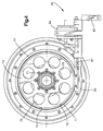
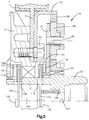
- FIG. 1 is a fragmentary axial view, partly in cross-section and partly in plan view, of a typical fluid coupling device including the present invention.
- FIG. 2 is a fragmentary, enlarged axial cross-section, similar to FIG. 1, of the speed increasing gearing of the present invention.
- FIG. 3 is a transverse cross section, looking from the right in FIG. 1, but on a smaller scale than FIG. 1, with certain parts remove to illustrate the speed increasing gearing of the present invention.
- FIG. 4 is a plan view, also taken from the right in FIG. 1, and on about the same scale as FIG. 3, illustrating the actuator utilized with the present invention.
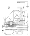
- FIG. 5 is an enlarged, fragmentary axial cross-section, similar to FIG. 2, illustrating an alternative embodiment of the present invention.
- FIG. 6 is an enlarged, fragmentary axial cross-section, similar to FIGS. 2 and 5, illustrating another alternative embodiment of the present invention.
- FIG. 1 illustrates one preferred form of a fluid coupling device (viscous fan drive) including the present invention.
- the fluid coupling device illustrated in FIG. 1 may be viewed generally as including three different portions, including a fairly conventional fluid coupling device, generally designated 11, a speed increasing mechanism, generally designated 13, and a radiator cooling fan F (shown only fragmentarily).
- a fairly conventional fluid coupling device generally designated 11
- a speed increasing mechanism generally designated 13
- a radiator cooling fan F shown only fragmentarily
- the fluid coupling device 11 includes an input coupling member 15, and an output coupling assembly including a die cast housing member 17 and a die cast cover member 19, the members 17 and 19 being secured together, such as by a rollover of the outer periphery of the cover member 19, as is well known in the art.
- the fluid coupling device 11 includes an input shaft 21 on which the input coupling member 15 is mounted.
- the input shaft 21 is rotatably driven, typically by means of an externally threaded shaft (not shown) which is driven by the engine, and which is in threaded engagement with an internally threaded hexagonal portion 23.
- the input shaft 21 functions as a support for the inner race of a bearing set 25, which is seated on the inside diameter of the housing member 17.
- the forward end (left end in FIG. 1) of the input shaft 21 has an interference fit between a serrated or knurled portion 27 and an opening defined by a hub portion 29 of the input coupling member 15. As a result, rotation of the input shaft 21 causes rotation of the input coupling member 15.
- the housing member 17 and the cover member 19 cooperate to define a fluid chamber which is separated, by means of a circular valve plate 31, into a fluid operating chamber 33 and a fluid reservoir chamber 35, such that the input coupling member 15 is disposed within the operating chamber 33.
- the cover member 19 defines a generally cylindrical shaft support portion (not shown in FIG. 1), and rotatably disposed within the shaft support portion is a valve shaft (not shown), extending outwardly (to the left in FIG. 1) through the cover member 19.
- a valve shaft (not shown), extending outwardly (to the left in FIG. 1) through the cover member 19.
- Attached to the inner end (right end in FIG. 1) of the valve shaft is a valve arm (not shown), and operatively associated with the outer end of the valve shaft is a temperature responsive bimetal element, comprising a coil member (not shown).
- a temperature responsive bimetal element comprising a coil member (not shown).
- changes in ambient air temperature change the shape of the coil member, thus moving the valve arm and controlling the flow of fluid from the reservoir chamber 35 to the operating chamber 33, through a fill opening 45 formed in the valve plate 31.
- the portions of the fluid coupling device 11 illustrated and described up to this point may be better understood by reference to U.S. Patent No. 4,974,
- the speed increasing mechanism 13 comprises a planetary gear set, although those skilled in the art will understand that the invention is not so limited.
- annular planet carrier assembly Disposed about the input shaft 21, just forward of the hexagonal portion 23, is an annular planet carrier assembly, including a planet carrier member 47, which is fixed to the input shaft 21, and a plurality of planet carrier pins 49, fixed to the planet carrier 47.
- a bearing set 51 Disposed about the radially inner hub of the planet carrier 47 is a bearing set 51, and mounted concentrically about the bearing set 51 is a sun gear 53.
- the sun gear 53 is in toothed engagement with a plurality of planet gears 55, each of the planet gears 55 being rotatably mounted on its respective planet carrier pin 49, and supported thereon by a suitable bearing set 57.
- Each of the planet gears 55 is in toothed engagement with a set of teeth disposed about the interior of a ring gear 59.
- the ring gear 59 is fixed to rotate with a housing member 61, as by any of several suitable means. It is one important aspect of the present invention that the housing member 61 is attached to the housing member 17 of the fluid coupling device 11, as by a plurality of bolts 63, and at the same time, is attached to the cooling fan F, as by means of a plurality of bolts 65. The significance of this aspect of the invention will become apparent in connection with the subsequent description of the operation of the invention.
- the mechanism 13 includes a stamped cover member 67 (which is removed in FIG. 3 to show the gears) which is attached to the housing member 61, and extends radially inwardly, such that the various gear meshes are enclosed, and protected from dirt, contamination, etc.
- a stamped cover member 67 Disposed radially between the bearing set 51 and the sun gear 53, and fixed to rotate with the sun gear 53 is an annular grounding member 69 which is attached, by means of a plurality of bolts 71, only one of which is shown in FIG. 2, to an annular brake disc 73.
- the brake disc 73 includes an outer cylindrical engagement portion 75, which is surrounded by a brake band 77.
- the brake disc 73 preferably defines a number of cutout portions 79, to make the disc 73 lighter and to facilitate the flow of cooling air around and through the mechanism.
- an actuator assembly generally designated 81, which would typically be fixed, relative to the vehicle engine, by means of a mounting bracket 83.
- the actuator assembly 81 comprises an electromagnetic solenoid 84 which includes a fixed link member 85 engaging one end of the brake band 77, and a moveable actuator member 87 engaging the other end of the brake band 77.
- the actuator assembly 81 When the actuator assembly 81 receives an appropriate electrical input signal at the solenoid 84, the coil within the solenoid 84 is energized, in a manner well known to those skilled in the art moving the actuator member 87 to the left in FIG. 4, and thus tightening the brake band 77 about the engagement portion 75 of the brake disc 73. Therefore, because the actuator assembly 81 is "grounded" (i.e., attached to the vehicle engine), the brake band 77, the brake disc 73, the annular grounding member 69 and the sun gear 53 are all similarly grounded (i.e., prevented from rotating, relative to the vehicle engine).
- the sun gear 53 has 36 teeth
- the speed increasing mechanism 13 does not increase the input speed to the input coupling member 15 of the viscous fan drive 11, but instead, directly drives (“overdrives") the output of the fluid coupling device 11.
- the ring gear 59 may be attached to, and directly drive, any one of the input coupling member 15, the housing member 17, the cover member 19, or the cooling fan F, and references hereinafter, and in the appended claims, to the output portion (ring gear 59) of the planetary gear set being in driving relationship to one of the first and second coupling members will be understood to mean and include any of the above.
- the housing member 61 within which the ring gear 59 is disposed is as described previously, attached to both the housing member 17 and the cooling fan F, whereby a forward wall portion 89 of the housing 61 also serves as the "spider" whereby torque is transmitted from the fan drive housing 17 to the fan F, which is attached to a radially outer portion 91 of the housing 61.
- the electrical input signal to the actuator assembly 81 is discontinued, and the moveable actuator 87 is retracted, thus permitting the brake band 77 to expand, such that the brake disc 73 and grounding member 69 are no longer grounded.
- the planet carrier 47 still rotates clockwise, but now, the ungrounded sun gear 53 and the ring gear 59 both rotate at generally the same speed of rotation, being in toothed engagement with the planet gears 55.
- the torque transfer path is from the input shaft 21 to the input coupling member 15, and from there, by means of viscous shear drag to the output of the viscous coupling 11, i.e., the housing member 17 and cover member 19.
- such a pumping arrangement should be able to pump fluid from the operating chamber to the reservoir chamber whether the input coupling 15 is rotating faster ("normal” operation), or whether the fan drive housing 17 is rotating faster (“overdrive” operation). It is believed to be within the ability of those skilled in the art to design the desired pumping arrangement.
- FIG. 5 there is illustrated an alternative embodiment of the present invention, in which elements which are the same or similar to those in the main embodiment bear the same reference numerals and new or substantially modified elements bear reference numerals in excess of "100".
- the embodiment of FIG. 5 does not include the stamped cover member 67 shown in FIG. 2, and the main housing comprises a stamped housing 101 which is bolted to the body 17, along with a spider S of the cooling fan F.
- the input shaft 21 is somewhat enlarged, by comparison to the embodiment of FIG. 1, and is hollow, to permit the insertion therein of an electromagnetic solenoid 103.
- Extending axially out of the solenoid 103 is an armature member 105, and on the forward end thereof (to the left in FIG. 5) is a plurality of radially extending members 107, passing through openings 108 in the shaft 21, and having a clutch member 109 disposed about the outer periphery of the members 107.
- the clutch member 109 includes a plurality of forwardly extending clutch teeth 111 which are disposed to engage a mating set of clutch teeth 113 formed on the rearward surface of the input coupling member 15.
- armature member 105 Disposed on the rearwardly extending portion of the armature member 105 is an a plurality of radially extending members 115, passing through openings 116 in the shaft 21, and having a clutch member 117 disposed about the outer periphery of the members 115.
- a clutch member 117 Formed on a rearward surface of the clutch member 117 is a plurality of clutch teeth 119, the teeth 119 being shown in FIG. 5 in engagement with a set of clutch teeth 121 formed on a forward surface of the planet carrier 47.
- the input shaft 21 includes a spring seat portion 123, and seated thereagainst is a coiled spring member 125, normally biasing the armature 105 and the members 107 and 115 toward a "forward" position in which the clutch teeth 111 are in engagement with the clutch teeth 113.
- This is the unactuated or de-energized condition of the solenoid 103, whereby drive torque is transmitted through the input shaft 21 to the input coupling member 15, and the fan drive operates in its normal viscous shear mode, i.e., assuming that there is fluid in the operating chamber.
- the clutch teeth 119 and 121 are out of engagement, such that no torque is being transmitted to the planet carrier 47.
- the solenoid 103 When, for example, the engine speed is relatively low, the solenoid 103 is energized, moving the armature 105 and members 107 and 115, overcoming the bias of the spring 125, to the position shown in FIG. 5 in which the clutch teeth 111 and 113 are out of engagement and the clutch teeth 119 and 121 are in engagement. In this energized position, input torque is transmitted by means of the input shaft 21 to the planet carrier 47, to "overdrive" the housing 101, housing member 17, and the cooling fan F, in the same manner as was described in connection with the FIG. 1 embodiment.
- the important aspect of the FIG. 5 embodiment is that, with the solenoid 103 energized, and the clutch teeth 111 and 113 disengaged, and no torque is transmitted from the input shaft 21 to the input coupling member 15.
- no input torque is being wasted in an attempt to rotate the input coupling member 15, and overcome the viscous shear drag between the member 15 and the housing member 17, which is, at this time, being driven faster than the input member 15.
- FIG. 6 another alternative embodiment of the invention will be described, in which like elements bear like numerals, and new or substantially modified elements bear reference numerals in excess of "200".
- the speed increasing mechanism 13 is internal to the fluid coupling device 11, the primary objective of the FIG. 6 embodiment being a smaller, simpler, and more compact device.
- the embodiment of FIG. 6 is preferably a "front land and groove" fluid coupling on which the lands and grooves are formed on a "forward" surface of the input coupling member 201, and are in interdigitated relationship with lands and grooves formed on a rearward surface of the cover member 203.
- the input shaft 21 is in fixed, driving relationship with the input coupling member 201, in the normal manner.
- a sun gear bearing 204 Surrounding the forward portion of the input shaft 21 is a sun gear bearing 204, and rotatably supported thereon is the sun gear 53.
- the sun gear 53 of the FIG. 6 embodiment has integrally formed therewith a cylindrical grounding portion 205, which extends rearwardly a sufficient distance to permit engagement, for purposes of grounding the sun gear 53, in the manner described in connection with the embodiment of FIG. 1.
- the input coupling member 201 serves as the planet carrier for the speed increasing mechanism, such that the planet carrier pins 207 are attached to the input member 201, or are formed integrally therewith as shown in FIG. 6, and the carrier pins 207 have the planet gears 55 rotatably mounted thereon.
- the coupling device of FIG. 6 includes a housing member 209, which also serves to support a ring gear 211 of the planetary gear set. Ring gear teeth are formed about the inner periphery of the ring gear 211, and are in engagement with the teeth of the planet gears 55.
Landscapes
- Engineering & Computer Science (AREA)
- General Engineering & Computer Science (AREA)
- Mechanical Engineering (AREA)
- Chemical & Material Sciences (AREA)
- Combustion & Propulsion (AREA)
- Structure Of Transmissions (AREA)
- General Details Of Gearings (AREA)
Claims (15)
- Fluidkopplungsvorrichtung mit einem ersten drehbaren Kopplungsbauteil (17), welches eine Drehachse (A) und eine darin befindliche Fluidkammer mit einer Fluidbetätigungskammer (33) festlegt, einem zweiten drehbaren Kopplungsbauteil (15), welches in der Fluidbetätigungskammer (33) angeordnet ist und relativ bezüglich des ersten Kopplungsbauteils (17) drehbar ist, um auf dieses ein Drehmoment in Abhängigkeit von der Anwesenheit von viskosem Fluid in der Fluidbetätigungskammer (33) zu übertragen, und einer Antriebsanordnung (21), die in Antriebsbeziehung mit dem zweiten Kopplungsbauteil (15) steht und betätigbar ist, um ein Eingangsdrehmoment auf dieses zu übertragen; wobei die Fluidkopplungsvorrichtung ferner eine Drehzahlerhöhungsanordnung (13) aufweist, die einen Antriebsabschnitt (47) in Antriebsbeziehung mit der Antriebsanordnung (21) sowie einen Abtriebsabschnitt (59) in Antriebsbeziehung mit dem ersten drehbaren Kopplungsbauteil (17) aufweist; dadurch gekennzeichnet, daßa) die Drehzahlerhöhungsanordnung (13) eine Getriebeanordnung aufweist;b) der Abtriebsabschnitt (59) relativ zu dem ersten drehbaren Kopplungsbauteil (17) feststehend ist;c) eine Betätigungsanordung (81) für die Geschwindigkeitserhöhungs-Getriebeanordnung (13) vorgesehen ist, die einen ersten betätigten Zustand aufweist, in welchem die Drehzahlerhöhungsgetriebeanordnung (13) ein Eingangsdrehmoment von der Antriebsanordnung (21) auf das erste drehbare Kopplungsbauteil (17) bei einer Drehzahl überträgt, die größer ist als diejenige der Antriebsanordnung; undd) die Betätigungsanordnung einen zweiten unbetätigten Zustand aufweist, in welchem im wesentlichen das gesamte Eingangsdrehmoment von der Antriebsanordnung (21) auf das zweite drehbare Kopplungsbauteil (15) übertragen wird.
- Fluidkopplungsvorrichtung gemäß Anspruch 1, dadurch gekennzeichnet, daß in dem zweiten, unbetätigten Zustand der Betätigungsanordnung (81) das gesamte Eingangsdrehmoment von der Antriebsanordnung (21) auf das zweite drehbare Kopplungsbauteil (15) bei einer Drehzahl übertragen wird, die im wesentlichen derjenigen der Antriebsanordnung (21) entspricht.
- Fluidkopplungsvorrichtung gemäß Anspruch 1 oder 2, gekennzeichnet durch eine Abdeckanordnung (19), die dem ersten drehbaren Kopplungsbauteil (17) zugeordnet ist, um dazwischen die Fluidkammer zu bilden, sowie eine Ventilanordnung, die angeordnet ist, um die Fluidkammer in die Fluidbetätigungskammer (33) und eine Fluidvorratskammer (35) zu unterteilen.
- Fluidkopplungsvorrichtung gemäß Anspruch 1 oder 2, dadurch gekennzeichnet, daß die Ventilanordnung eine Ventilplatte (31) umfaßt, welche die Fluidbetätigungskammer (33) und die Fluidvorratskammer (35) voneinander trennt und einen Fluidanschluß (45) aufweist, welcher vorgesehen ist, um für eine Fluidverbindung zwischen der Betätigungskammer und der Vorratskammer zu sorgen.
- Fluidkopplungsvorrichtung gemäß Anspruch 4, dadurch gekennzeichnet, daß die Ventilanordnung ferner eine Ventilanordnung aufweist, die in Abhängigkeit von Veränderungen eines vorbestimmten Zustands zwischen einer ersten Position, in welcher im wesentlichen ein Fluidstrom durch den Fluidanschluß (45) verhindert wird, und einer zweiten Position verstellbar ist, in welcher ein wesentlicher Fluidstrom durch den Fluidanschluß (45) erlaubt ist.
- Fluidkopplungsvorrichtung gemäß Anspruch 5, dadurch gekennzeichnet, daß der vorbestimmte Zustand eine externe Temperatur umfaßt, die ein Maß für die Motorkühlmitteltemperatur ist.
- Fluidkopplungsvorrichtung gemäß Anspruch 1 oder 2, dadurch gekennzeichnet, daß die Drehzahlerhöhungsgetriebeanordnung (13) einen Planetengetriebesatz mit einem Sonnenrad (53), einem Ringrad (59) und einer Mehrzahl von Planetenrädern (55) umfaßt, die radial zwischen dem Sonnenrad und dem Ringrad angeordnet sind.
- Fluidkopplungsvorrichtung gemäß Anspruch 7, dadurch gekennzeichnet, daß der Planetengetriebesatz (13) einen Planetenträger (47) umfaßt, dessen Achse koinzident bezüglich der Drehachse (A) ist, wobei die Planetenräder (55) angeordnet sind, um um eine Achse (49) umzulaufen, die bezüglich des Planetenträgers (47) feststehend ist, und wobei der Planetenträger den Antriebsabschnitt bildet.
- Fluidkopplungsvorrichtung gemäß Anspruch 7, dadurch gekennzeichnet, daß der Abtriebsabschnitt das Ringrad (59) umfaßt und ein Getriebegehäuse (61) vorgesehen ist, welches relativ zu dem Ringrad und dem ersten drehbaren Kopplungsbauteil (17) nicht drehbar ist.
- Fluidkopplungsvorrichtung gemäß Anspruch 9, dadurch gekennzeichnet, daß das Getriebegehäuse (61) einen radial innenliegenden Abschnitt (89), der bezüglich des ersten drehbaren Kopplungsbauteils (17) feststehend ist, einen radial im mittleren Bereich liegenden Abschnitt (61), der bezüglich des Ringrads (59) feststehend ist, sowie einen radial außenliegenden Abschnitt (91) aufweist, der für die Befestigung eines Kühlventilators (F) ausgebildet ist.
- Fluidkopplungsvorrichtung gemäß Anspruch 7, dadurch gekennzeichnet, daß das Sonnenrad (53) die Antriebsanordnung (21) umgibt, die Betätigungsanordnung (81) eine Bremsanordnung (69, 73, 77) aufweist, die in Wirkverbindung mit dem Sonnenrad (55) steht, in dem ersten betätigten Zustand die Bremsanordnung in Eingriff steht, um eine Drehung des Sonnenrads zu verhindern, und in dem zweiten, unbetätigten Zustand die Bremsanordnung (69, 73, 77) außer Eingriff steht, um eine Drehung des Sonnenrads (55) zu erlauben.
- Fluidkopplungsvorrichtung gemäß Anspruch 1, dadurch gekennzeichnet, daß die Drehzahlerhöhungsgetriebeanordnung (13) innenliegend bezüglich des ersten drehbaren Kopplungsbauteils (203, 209) angeordnet ist und das zweite drehbare Kopplungsbauteil (201) den Antriebsabschnitt bezüglich der Drehzahlerhöhungsgetriebeanordnung umfaßt.
- Fluidkopplungsvorrichtung gemäß Anspruch 1 oder 2, dadurch gekennzeichnet, daß die Drehzahlerhöhungsgetriebeanordnung (13) außenliegend bezüglich des ersten drehbaren Kopplungsbauteils (17) angeordnet ist.
- Fluidkopplungsvorrichtung mit einem ersten drehbaren Kopplungsbauteil (17), welches eine Drehachse (A) und eine darin befindliche Fluidkammer festlegt, welche eine Fluidbetätigungskammer (33) aufweist, einem zweiten drehbaren Kopplungsbauteil (15), welches in der Fluidbetätigungskammer (33) angeordnet ist und relativ zu dem ersten Kopplungsbauteil (17) drehbar ist, um in Abhängigkeit von der Anwesenheit von viskosem Fluid in der Fluidbetätigungskammer Drehmoment auf das erste Fluidkopplungsbauteil (17) zu übertragen, sowie einer Antriebsanordnung (21), die in Antriebsverbindung mit dem zweiten Kopplungsbauteil (15) steht und betätigbar ist, um Eingangsdrehmoment auf dieses zu übertragen; wobei die Fluidkopplungsvorrichtung ferner eine Drehzahlerhöhungsanordnung (13) aufweist, die einen Abtriebsabschnitt (59) in Antriebsbeziehung mit dem ersten drehbaren Kopplungsbauteil (17) sowie einen Antriebsabschnitt (47) umfaßt; dadurch gekennzeichnet, daßa) die Drehzahlerhöhungsanordnung (13) eine Getriebeanordnung umfaßt;b) eine Kupplungsanordnung (111, 113, 117, 119, 121) für die Drehzahlerhöhungsgetriebeanordnung (13) vorgesehen ist, die einen ersten, betätigten Zustand, in welchem die Drehzahlerhöhungsgetriebeanordnung (13) Eingangsdrehmoment von der Antriebsanordnung (21) auf das erste drehbare Kopplungsbauteil (17) bei einer Drehzahl, die größer als diejenige der Antriebsanordnung ist, dadurch überträgt, daß für einen Kupplungseingriff der Antriebsanordnung (21) mit dem Antriebsabschnitt (47) der Drehzahlerhöhungsgetriebeanordnung (13) gesorgt wird; undc) die Kupplungsanordnung (111, 113, 117, 119, 121) einen zweiten, nicht betätigten Zustand aufweist, in welchem im wesentlichen das gesamte Eingangsdrehmoment von der Antriebsanordnung (21) auf das zweite drehbare Kopplungsbauteil (15) übertragen wird und in welchem die Antriebsanordnung (21) nicht in Eingriff mit dem Antriebsabschnitt (47) der Drehzahlerhöhungsgetriebeanordnung (13) steht.
- Fluidkopplungsvorrichtung gemäß Anspruch 14, dadurch gekennzeichnet, daß die Kupplungsanordnung (111, 113, 117, 119) in dem ersten betätigten Zustand das zweite drehbare Kopplungsbauteil (15) von der Antriebsanordnung (21) löst und in dem zweiten, nicht betätigten Zustand für einen Kupplungseingriff des zweiten drehbaren Kopplungsbauteils (15) mit der Antriebsanordnung (21) sorgt.
Applications Claiming Priority (2)
| Application Number | Priority Date | Filing Date | Title |
|---|---|---|---|
| US705351 | 1996-08-29 | ||
| US08/705,351 US5782715A (en) | 1996-08-29 | 1996-08-29 | Dual ratio viscous fan drive |
Publications (2)
| Publication Number | Publication Date |
|---|---|
| EP0826892A1 EP0826892A1 (de) | 1998-03-04 |
| EP0826892B1 true EP0826892B1 (de) | 2000-11-22 |
Family
ID=24833078
Family Applications (1)
| Application Number | Title | Priority Date | Filing Date |
|---|---|---|---|
| EP97114605A Expired - Lifetime EP0826892B1 (de) | 1996-08-29 | 1997-08-22 | Zweigangsflüssigkeitsreibungsantrieb |
Country Status (5)
| Country | Link |
|---|---|
| US (1) | US5782715A (de) |
| EP (1) | EP0826892B1 (de) |
| JP (1) | JPH1082433A (de) |
| KR (1) | KR100332207B1 (de) |
| DE (1) | DE69703571T2 (de) |
Families Citing this family (13)
| Publication number | Priority date | Publication date | Assignee | Title |
|---|---|---|---|---|
| IT1292384B1 (it) * | 1997-06-19 | 1999-02-08 | Baruffaldi Spa | Dispositivo di trasmissione del moto a frizione elettromagnetica e rotismo epicicloidale per ventole di autoveicolo |
| DE19821096A1 (de) * | 1998-05-12 | 1999-11-18 | Behr Gmbh & Co | Antriebseinrichtung für den Kühllüfter eines Kraftfahrzeugmotors |
| DE19821098A1 (de) * | 1998-05-12 | 1999-11-18 | Behr Gmbh & Co | Antriebseinrichtung für den Kühllüfter eines Kraftfahrzeugmotors |
| DE10012648A1 (de) * | 2000-03-15 | 2001-10-04 | Mannesmann Sachs Ag | Fluidkupplung |
| US6789654B2 (en) | 2003-01-22 | 2004-09-14 | Caterpillar Inc | Multiple coupling fan drive |
| DE102005062666A1 (de) * | 2005-12-23 | 2007-06-28 | Behr Gmbh & Co. Kg | Antrieb für eine Strömungsmaschine, insbesondere für einen Lüfter eines Kraftfahrzeuges |
| GB2457878A (en) * | 2008-02-26 | 2009-09-02 | Agco Sa | Variable speed fan drive |
| KR100901436B1 (ko) * | 2008-08-04 | 2009-06-05 | 서달원 | 주행속도 향상을 위한 자전거용 가속장치 |
| JP6200060B2 (ja) | 2013-03-14 | 2017-09-20 | ホートン, インコーポレイテッド | 最低出力速度を備えた粘性クラッチ |
| US9470278B1 (en) | 2015-11-10 | 2016-10-18 | Borgwarner Inc. | Apparatus employing shear forces to transmit energy having flow altering structures configured to increase heat rejection from a working fluid and related method |
| ITUB20156050A1 (it) * | 2015-12-01 | 2017-06-01 | Cnh Ind Italia Spa | Trasmissione per ventola con un'unita' perfezionata di innesto a slittamento variabile per un motore a combustione interna |
| JP6697803B2 (ja) * | 2016-07-07 | 2020-05-27 | 臼井国際産業株式会社 | 流体式ファンクラッチ |
| EP3990805A4 (de) | 2019-06-28 | 2023-11-01 | Horton, Inc. | Übertragungssystem mit planetengetriebe mit betrieb im vorwärts- und rückwärtsmodus |
Family Cites Families (16)
| Publication number | Priority date | Publication date | Assignee | Title |
|---|---|---|---|---|
| US4040310A (en) * | 1975-12-01 | 1977-08-09 | Pierre Giroux | Hydraulic torque converting wheel |
| US4064980A (en) * | 1976-10-12 | 1977-12-27 | Eaton Corporation | Dual speed viscous fluid coupling |
| DE3004581A1 (de) * | 1980-02-08 | 1981-08-13 | Klöckner-Humboldt-Deutz AG, 5000 Köln | Hydrostatische kupplung |
| US4351425A (en) * | 1980-12-29 | 1982-09-28 | Eaton Corporation | Dual stage control for viscous fluid coupling |
| US4476744A (en) * | 1981-04-10 | 1984-10-16 | Crooks James W | Multi-speed fan drive apparatus |
| DE3322779C2 (de) * | 1983-06-24 | 1986-09-18 | Süddeutsche Kühlerfabrik Julius Fr. Behr GmbH & Co KG, 7000 Stuttgart | Flüssigkeitsreibungskupplung |
| US4706521A (en) * | 1986-07-31 | 1987-11-17 | Bendix Electronics Limited | Bellows activated underdrive two speed accessory drive |
| US4932928A (en) * | 1988-12-05 | 1990-06-12 | Crockett Samuel J | Shiftless, continuously-aligning transmission |
| US4974712A (en) * | 1989-09-13 | 1990-12-04 | Eaton Corporation | Fluid coupling device and improved valving therefor |
| US4987985A (en) * | 1989-10-30 | 1991-01-29 | Ford Motor Company | Automotive fan drive train assembly having a hydraulic coupler and a viscous clutch |
| DE4041158C1 (de) * | 1990-12-21 | 1992-08-20 | Mercedes-Benz Aktiengesellschaft, 7000 Stuttgart, De | |
| DE4041568A1 (de) * | 1990-12-22 | 1992-06-25 | Behr Gmbh & Co | Luefterantrieb mit fluessigkeitsreibungskupplung |
| US5203747A (en) * | 1991-10-10 | 1993-04-20 | Warren Walter S | Integrated hydro-mechanical transmission |
| US5152384A (en) * | 1991-10-31 | 1992-10-06 | Eaton Corporation | Viscous fluid coupling and remote control assembly therefor |
| DE9211473U1 (de) * | 1992-08-26 | 1992-10-29 | Fichtel & Sachs Ag, 8720 Schweinfurt | Antriebsvorrichtung für den Kühlerlüfter bei Kraftfahrzeugen |
| US5558192A (en) * | 1995-03-27 | 1996-09-24 | Eaton Corporation | Fluid coupling and external control therefor |
-
1996
- 1996-08-29 US US08/705,351 patent/US5782715A/en not_active Expired - Lifetime
-
1997
- 1997-08-22 EP EP97114605A patent/EP0826892B1/de not_active Expired - Lifetime
- 1997-08-22 DE DE69703571T patent/DE69703571T2/de not_active Expired - Fee Related
- 1997-08-27 KR KR1019970041503A patent/KR100332207B1/ko not_active Expired - Fee Related
- 1997-08-29 JP JP9233859A patent/JPH1082433A/ja active Pending
Also Published As
| Publication number | Publication date |
|---|---|
| EP0826892A1 (de) | 1998-03-04 |
| US5782715A (en) | 1998-07-21 |
| KR19980019076A (ko) | 1998-06-05 |
| KR100332207B1 (ko) | 2002-10-18 |
| JPH1082433A (ja) | 1998-03-31 |
| DE69703571D1 (de) | 2000-12-28 |
| DE69703571T2 (de) | 2001-05-31 |
Similar Documents
| Publication | Publication Date | Title |
|---|---|---|
| EP0826892B1 (de) | Zweigangsflüssigkeitsreibungsantrieb | |
| EP0870943B1 (de) | Hochbelastbarer viskose Ventilatorantrieb sowie Haltevorrichtung dafür | |
| US3300002A (en) | Bi-directional roller clutch with differential speed responsive pilot clutch | |
| US4817753A (en) | Interaxle differential restriction device for vehicle four wheel drive systems | |
| US5197583A (en) | Torque transmission device | |
| US5152383A (en) | Viscous fluid coupling and external actuator assembly therefor | |
| US6953411B2 (en) | Electronically-tuned hydromechanical coupling | |
| US5398792A (en) | Clutch device | |
| US5377800A (en) | Hydraulically-actuated shift system for a transfer case | |
| US5503602A (en) | Clutch actuating device having pilot clutches for use in a vehicle interaxle differential | |
| JP3936236B2 (ja) | デファレンシャル装置 | |
| WO2003052292A2 (en) | Rear drive module for all-wheel drive vehicle | |
| US6216841B1 (en) | Hydraulic clutch | |
| US5456642A (en) | Geared traction unit | |
| KR0176723B1 (ko) | 점성유체 이음장치 및 그의 원격제어장치 | |
| EP0329408B1 (de) | Verteilereinrichtung für ein vierradgetriebenes Kraftfahrzeug | |
| US5338266A (en) | Differential transmission device and viscous coupler, especially for a motor vehicle | |
| EP0248577B1 (de) | Kraftverteilervorrichtung für Vierradantrieb | |
| EP0393285B1 (de) | Kupplung für Kraftübertragung | |
| EP1112887B1 (de) | Vorderradantriebskupplung für Traktoren | |
| JP3294650B2 (ja) | 農作業車の伝動構造 | |
| EP0528547B1 (de) | Leistungsübertragungseinrichtung mit T-förmiger Anordnung | |
| US4907472A (en) | Power transmitting system for a four-wheel drive vehicle | |
| JPH0464747A (ja) | 差動制限装置 | |
| JP2001221255A (ja) | 4輪駆動車のトランスアクスル |
Legal Events
| Date | Code | Title | Description |
|---|---|---|---|
| PUAI | Public reference made under article 153(3) epc to a published international application that has entered the european phase |
Free format text: ORIGINAL CODE: 0009012 |
|
| AK | Designated contracting states |
Kind code of ref document: A1 Designated state(s): DE FR GB IT SE |
|
| AX | Request for extension of the european patent |
Free format text: AL;LT;LV;RO;SI |
|
| 17P | Request for examination filed |
Effective date: 19980416 |
|
| 17Q | First examination report despatched |
Effective date: 19980702 |
|
| AKX | Designation fees paid |
Free format text: DE FR GB IT SE |
|
| RBV | Designated contracting states (corrected) |
Designated state(s): DE FR GB IT SE |
|
| GRAG | Despatch of communication of intention to grant |
Free format text: ORIGINAL CODE: EPIDOS AGRA |
|
| RAP1 | Party data changed (applicant data changed or rights of an application transferred) |
Owner name: BORG-WARNER AUTOMOTIVE, INC. |
|
| GRAG | Despatch of communication of intention to grant |
Free format text: ORIGINAL CODE: EPIDOS AGRA |
|
| GRAG | Despatch of communication of intention to grant |
Free format text: ORIGINAL CODE: EPIDOS AGRA |
|
| GRAH | Despatch of communication of intention to grant a patent |
Free format text: ORIGINAL CODE: EPIDOS IGRA |
|
| GRAH | Despatch of communication of intention to grant a patent |
Free format text: ORIGINAL CODE: EPIDOS IGRA |
|
| GRAA | (expected) grant |
Free format text: ORIGINAL CODE: 0009210 |
|
| RIN1 | Information on inventor provided before grant (corrected) |
Inventor name: GODLEW, DAVID PAUL Inventor name: DEBRABANDER, JAMES RICHARD Inventor name: WALTON, ERLEN BUSCH |
|
| AK | Designated contracting states |
Kind code of ref document: B1 Designated state(s): DE FR GB IT SE |
|
| PG25 | Lapsed in a contracting state [announced via postgrant information from national office to epo] |
Ref country code: IT Free format text: LAPSE BECAUSE OF FAILURE TO SUBMIT A TRANSLATION OF THE DESCRIPTION OR TO PAY THE FEE WITHIN THE PRESCRIBED TIME-LIMIT;WARNING: LAPSES OF ITALIAN PATENTS WITH EFFECTIVE DATE BEFORE 2007 MAY HAVE OCCURRED AT ANY TIME BEFORE 2007. THE CORRECT EFFECTIVE DATE MAY BE DIFFERENT FROM THE ONE RECORDED. Effective date: 20001122 |
|
| REF | Corresponds to: |
Ref document number: 69703571 Country of ref document: DE Date of ref document: 20001228 |
|
| ET | Fr: translation filed | ||
| PLBE | No opposition filed within time limit |
Free format text: ORIGINAL CODE: 0009261 |
|
| STAA | Information on the status of an ep patent application or granted ep patent |
Free format text: STATUS: NO OPPOSITION FILED WITHIN TIME LIMIT |
|
| 26N | No opposition filed | ||
| REG | Reference to a national code |
Ref country code: GB Ref legal event code: IF02 |
|
| PGFP | Annual fee paid to national office [announced via postgrant information from national office to epo] |
Ref country code: GB Payment date: 20030702 Year of fee payment: 7 |
|
| PGFP | Annual fee paid to national office [announced via postgrant information from national office to epo] |
Ref country code: FR Payment date: 20030804 Year of fee payment: 7 |
|
| PGFP | Annual fee paid to national office [announced via postgrant information from national office to epo] |
Ref country code: SE Payment date: 20030805 Year of fee payment: 7 |
|
| PGFP | Annual fee paid to national office [announced via postgrant information from national office to epo] |
Ref country code: DE Payment date: 20030829 Year of fee payment: 7 |
|
| PG25 | Lapsed in a contracting state [announced via postgrant information from national office to epo] |
Ref country code: GB Free format text: LAPSE BECAUSE OF NON-PAYMENT OF DUE FEES Effective date: 20040822 |
|
| PG25 | Lapsed in a contracting state [announced via postgrant information from national office to epo] |
Ref country code: SE Free format text: LAPSE BECAUSE OF NON-PAYMENT OF DUE FEES Effective date: 20040823 |
|
| PG25 | Lapsed in a contracting state [announced via postgrant information from national office to epo] |
Ref country code: DE Free format text: LAPSE BECAUSE OF NON-PAYMENT OF DUE FEES Effective date: 20050301 |
|
| EUG | Se: european patent has lapsed | ||
| GBPC | Gb: european patent ceased through non-payment of renewal fee |
Effective date: 20040822 |
|
| PG25 | Lapsed in a contracting state [announced via postgrant information from national office to epo] |
Ref country code: FR Free format text: LAPSE BECAUSE OF NON-PAYMENT OF DUE FEES Effective date: 20050429 |
|
| REG | Reference to a national code |
Ref country code: FR Ref legal event code: ST |