EP0826870B1 - Apparatus for controlling timings of exhaust valves and method thereof - Google Patents
Apparatus for controlling timings of exhaust valves and method thereof Download PDFInfo
- Publication number
- EP0826870B1 EP0826870B1 EP97113769A EP97113769A EP0826870B1 EP 0826870 B1 EP0826870 B1 EP 0826870B1 EP 97113769 A EP97113769 A EP 97113769A EP 97113769 A EP97113769 A EP 97113769A EP 0826870 B1 EP0826870 B1 EP 0826870B1
- Authority
- EP
- European Patent Office
- Prior art keywords
- engine
- timing
- opening
- exhaust valve
- exhaust
- Prior art date
- Legal status (The legal status is an assumption and is not a legal conclusion. Google has not performed a legal analysis and makes no representation as to the accuracy of the status listed.)
- Expired - Lifetime
Links
- 238000000034 method Methods 0.000 title claims description 20
- 238000002485 combustion reaction Methods 0.000 claims description 21
- 230000007246 mechanism Effects 0.000 claims description 16
- 238000001514 detection method Methods 0.000 claims description 8
- 230000003197 catalytic effect Effects 0.000 description 22
- 239000007789 gas Substances 0.000 description 7
- XLYOFNOQVPJJNP-UHFFFAOYSA-N water Substances O XLYOFNOQVPJJNP-UHFFFAOYSA-N 0.000 description 7
- QVGXLLKOCUKJST-UHFFFAOYSA-N atomic oxygen Chemical compound [O] QVGXLLKOCUKJST-UHFFFAOYSA-N 0.000 description 6
- 239000001301 oxygen Substances 0.000 description 6
- 229910052760 oxygen Inorganic materials 0.000 description 6
- 239000000446 fuel Substances 0.000 description 4
- 230000003213 activating effect Effects 0.000 description 3
- 230000004913 activation Effects 0.000 description 3
- 230000002542 deteriorative effect Effects 0.000 description 3
- 230000008859 change Effects 0.000 description 2
- 239000000498 cooling water Substances 0.000 description 2
- 238000010586 diagram Methods 0.000 description 1
- 238000005516 engineering process Methods 0.000 description 1
- 238000010438 heat treatment Methods 0.000 description 1
- 230000001771 impaired effect Effects 0.000 description 1
- 239000000203 mixture Substances 0.000 description 1
- 230000001737 promoting effect Effects 0.000 description 1
- 230000004044 response Effects 0.000 description 1
- 230000000979 retarding effect Effects 0.000 description 1
- 238000011144 upstream manufacturing Methods 0.000 description 1
Images



Classifications
-
- F—MECHANICAL ENGINEERING; LIGHTING; HEATING; WEAPONS; BLASTING
- F02—COMBUSTION ENGINES; HOT-GAS OR COMBUSTION-PRODUCT ENGINE PLANTS
- F02D—CONTROLLING COMBUSTION ENGINES
- F02D13/00—Controlling the engine output power by varying inlet or exhaust valve operating characteristics, e.g. timing
- F02D13/02—Controlling the engine output power by varying inlet or exhaust valve operating characteristics, e.g. timing during engine operation
- F02D13/0242—Variable control of the exhaust valves only
- F02D13/0249—Variable control of the exhaust valves only changing the valve timing only
-
- F—MECHANICAL ENGINEERING; LIGHTING; HEATING; WEAPONS; BLASTING
- F01—MACHINES OR ENGINES IN GENERAL; ENGINE PLANTS IN GENERAL; STEAM ENGINES
- F01L—CYCLICALLY OPERATING VALVES FOR MACHINES OR ENGINES
- F01L1/00—Valve-gear or valve arrangements, e.g. lift-valve gear
- F01L1/34—Valve-gear or valve arrangements, e.g. lift-valve gear characterised by the provision of means for changing the timing of the valves without changing the duration of opening and without affecting the magnitude of the valve lift
- F01L1/344—Valve-gear or valve arrangements, e.g. lift-valve gear characterised by the provision of means for changing the timing of the valves without changing the duration of opening and without affecting the magnitude of the valve lift changing the angular relationship between crankshaft and camshaft, e.g. using helicoidal gear
- F01L1/34403—Valve-gear or valve arrangements, e.g. lift-valve gear characterised by the provision of means for changing the timing of the valves without changing the duration of opening and without affecting the magnitude of the valve lift changing the angular relationship between crankshaft and camshaft, e.g. using helicoidal gear using helically teethed sleeve or gear moving axially between crankshaft and camshaft
- F01L1/34406—Valve-gear or valve arrangements, e.g. lift-valve gear characterised by the provision of means for changing the timing of the valves without changing the duration of opening and without affecting the magnitude of the valve lift changing the angular relationship between crankshaft and camshaft, e.g. using helicoidal gear using helically teethed sleeve or gear moving axially between crankshaft and camshaft the helically teethed sleeve being located in the camshaft driving pulley
-
- F—MECHANICAL ENGINEERING; LIGHTING; HEATING; WEAPONS; BLASTING
- F02—COMBUSTION ENGINES; HOT-GAS OR COMBUSTION-PRODUCT ENGINE PLANTS
- F02D—CONTROLLING COMBUSTION ENGINES
- F02D41/00—Electrical control of supply of combustible mixture or its constituents
- F02D41/02—Circuit arrangements for generating control signals
- F02D41/021—Introducing corrections for particular conditions exterior to the engine
- F02D41/0235—Introducing corrections for particular conditions exterior to the engine in relation with the state of the exhaust gas treating apparatus
- F02D41/024—Introducing corrections for particular conditions exterior to the engine in relation with the state of the exhaust gas treating apparatus to increase temperature of the exhaust gas treating apparatus
-
- F—MECHANICAL ENGINEERING; LIGHTING; HEATING; WEAPONS; BLASTING
- F01—MACHINES OR ENGINES IN GENERAL; ENGINE PLANTS IN GENERAL; STEAM ENGINES
- F01L—CYCLICALLY OPERATING VALVES FOR MACHINES OR ENGINES
- F01L2201/00—Electronic control systems; Apparatus or methods therefor
-
- F—MECHANICAL ENGINEERING; LIGHTING; HEATING; WEAPONS; BLASTING
- F02—COMBUSTION ENGINES; HOT-GAS OR COMBUSTION-PRODUCT ENGINE PLANTS
- F02D—CONTROLLING COMBUSTION ENGINES
- F02D13/00—Controlling the engine output power by varying inlet or exhaust valve operating characteristics, e.g. timing
- F02D13/02—Controlling the engine output power by varying inlet or exhaust valve operating characteristics, e.g. timing during engine operation
- F02D2013/0292—Controlling the engine output power by varying inlet or exhaust valve operating characteristics, e.g. timing during engine operation in the start-up phase, e.g. for warming-up cold engine or catalyst
-
- F—MECHANICAL ENGINEERING; LIGHTING; HEATING; WEAPONS; BLASTING
- F02—COMBUSTION ENGINES; HOT-GAS OR COMBUSTION-PRODUCT ENGINE PLANTS
- F02D—CONTROLLING COMBUSTION ENGINES
- F02D41/00—Electrical control of supply of combustible mixture or its constituents
- F02D41/0002—Controlling intake air
- F02D2041/001—Controlling intake air for engines with variable valve actuation
-
- Y—GENERAL TAGGING OF NEW TECHNOLOGICAL DEVELOPMENTS; GENERAL TAGGING OF CROSS-SECTIONAL TECHNOLOGIES SPANNING OVER SEVERAL SECTIONS OF THE IPC; TECHNICAL SUBJECTS COVERED BY FORMER USPC CROSS-REFERENCE ART COLLECTIONS [XRACs] AND DIGESTS
- Y02—TECHNOLOGIES OR APPLICATIONS FOR MITIGATION OR ADAPTATION AGAINST CLIMATE CHANGE
- Y02T—CLIMATE CHANGE MITIGATION TECHNOLOGIES RELATED TO TRANSPORTATION
- Y02T10/00—Road transport of goods or passengers
- Y02T10/10—Internal combustion engine [ICE] based vehicles
- Y02T10/12—Improving ICE efficiencies
Definitions
- the present invention relates to an apparatus for controlling timings of exhaust valves and to a method thereof. More particularly, the invention relates to technology for promoting the activation of components in an exhaust system, such as oxygen sensor, catalytic converter and the like during the cold starting of an engine by controlling the timings for opening the exhaust valves.
- the ignition timing must be extremely retarded in order to sufficiently elevate the exhaust gas temperature causing, however, the operation performance and fuel efficiency to be deteriorated.
- the above-mentioned method B makes it necessary to provide a hardware such as air pump and valve for controlling the air supplied into the exhaust system, resulting in an increase in cost.
- the above-mentioned method C requires an increased cost for installing the heater and the like, and further necessitates improvements in the electric charging system of the engine so that an electric current can be supplied to the heater of a large capacity, resulting in an increase in cost.
- Document GB-A-2 267 310 discloses an apparatus for controlling timings of exhaust valves of an internal combustion engine.
- the apparatus comprises a variable valve timing mechanism for varying the timing for opening and closing an exhaust valve, wherein the timing for opening the exhaust valve is advanced by a predetermined angle by controlling said variable valve timing mechanism at the cold starting of the engine in order to promote the rise of temperature of an exhaust system connected to said exhaust valves.
- the timing for opening the exhaust valve is advanced when the temperature of the engine detected by an engine temperature means is lower than a predetermined temperature.
- the timing for opening the exhaust valve is advanced only when the engine is in a predetermined light-load operation state or in an idling state.
- Document EP 0 718 475 A1 discloses an engine having a camshaft for operating the exhaust valves associated with the engine cylinders and a camshaft setting device for advancing the camshaft angle to obtain rapid heating of the catalyser to its operation temperature upon cold starting of the engine.
- the object is solved by the subject matter of claim 1, and referring to the method, the object is solved by the subject matter of claim 8.
- the timing for opening the exhaust valve is advanced by a predetermined angle by a variable valve timing mechanism during the cold start of an engine, to thereby promote the elevation of temperature of an exhaust system.
- the timing for opening the exhaust valve is advanced for only a predetermined period of time depending upon the temperature of the engine at the time of start.
- the timing for opening the exhaust valve is advanced for only a period of time that corresponds to the temperature of the engine at the time of start, i.e., that corresponds to the temperature of the catalytic converter and the like.
- the timing for opening the exhaust valve is advanced for only a period of time that is enough for activating the catalytic converter and the like.
- the timing for opening the exhaust valve is advanced (opening timing is quickened) during the cold start of an engine, i.e., while the catalytic converter and oxygen sensor in the exhaust system are cold and inactive, so that the heat of combustion in a cylinder is positively discharged into the discharge system to elevate the temperature of the exhaust system.
- any engine equipped with a variable valve timing mechanism enables the catalytic converter and the like to activate in an early time by simply changing the control specifications. According to the method of advancing the timing for opening the exhaust valve, furthermore, the operation performance is less affected and the temperature rises more efficiently than when the temperature is elevated by retarding the ignition timing.
- variable valve timing mechanism may be the one in which the timing for opening and dosing the exhaust valve is changed by adjusting the phase of a cam shaft with respect to a crank shaft, as well as the one in which a plurality of cams are used being changed over, and may further be the one in which the cam shaft is moved in parallel to change the lift and timing.
- the timing for opening the exhaust valve is advanced by a predetermined angle during a predetermined period of time after the starting when the engine temperature at the time of start is equal to or lower than a predetermined temperature.
- the timing for opening the exhaust valve is not advanced from when the engine is started but is controlled during a predetermined period of time after the starting, so that controlling the timings for opening the valves will not affect the starting performance.
- a state until a predetermined period of time has elapsed after the complete combustion is detected as the starting state, and the timing for opening the exhaust valve is advanced by a predetermined angle during a subsequent predetermined period of time.
- the timing for opening the exhaust valve is not readily advanced after the completely burned state is established but is controlled after a predetermined period of time has elapsed from when the completely burned state is established. This makes it possible to avoid such an occurrence that the timing for opening the exhaust valve is advanced in an unstable state immediately after the start causing the engine loses stability.
- the complete combustion of the engine is judged when the rotational speed of the engine is equal to or higher than a predetermined rotational speed.
- the completely burned state is judged based upon whether an actual rotational speed of the engine has reached a rotational speed that meets the completely burned state or not.
- the completely burned state of the engine is properly judged, and the timing for opening the exhaust valve is properly controlled.
- the timing for opening the exhaust valve is advanced only when the engine is in a predetermined light-load operation state.
- the timing for opening the exhaust valve is not advanced when the engine is in a heavy-load operation state even within a predetermined period of time after the cold starting, but the timing for opening the exhaust valve is advanced only in a light-load operation state. This makes it possible to avoid such an occurrence that the timing for opening the exhaust valve is unnecessarily advanced in a state where the engine is in operation bearing a heavy-load generating sufficient amounts of heat of exhaust gases.
- a predetermined angle by which the timing for opening the exhaust valve is advanced is variably set depending upon the operation conditions of the engine.
- An internal combustion engine 1 shown in Fig. 1 is equipped with a cam shaft 2 of the intake side and a cam shaft 3 of the exhaust side which are independent from each other.
- a timing belt 7 wrapped around a crank pulley 6 is in mesh with cam pulleys 4 and 5 that are attached to the ends of the cam shafts 2 and 3, and the cam shafts 2 and 3 are rotatably driven in synchronism with the rotation of a crank shaft 8.
- the cam shaft 3 of the exhaust side is provided with a variable valve timing mechanism 10 that varies the timing for opening and closing an exhaust valve 9.
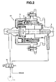
- variable valve timing mechanism 10 controls the phase between the crank shaft 8 and the cam shaft 3 of the exhaust side thereby to vary the timing for opening and closing the exhaust valve 9, and is constituted as concretely shown in Fig. 2.
- a plunger 11 is in mesh with the cam pulley 5 of the exhaust side and with the cam shaft 3 of the exhaust side via a helical gear 12.
- the cam shaft 3 of the exhaust side and the plunger 11 rotate together since the cam pulley 5 of the exhaust side is secured via the timing belt 7, and whereby the relative positions of the cam pulley 5 of the exhaust side and of the cam shaft 3 of the exhaust side undergo a change in the circumferential direction. Accordingly, the phase of the cam shaft 3 of the exhaust side changes relative to the crank shaft 8, and hence, the timing for opening and closing the exhaust valve 9 is shifted with the operation angle being maintained constant.
- the operation oil is fed to the plunger 11 being controlled by a solenoid valve 14.
- the position for feeding the operation oil and the drain position are changed over by the solenoid 14 in order to reciprocally move the plunger 11 in the axial direction.
- a control unit 20 for controlling the solenoid valve 14 receives signals from a crank angle sensor 21, a cam angle sensor 22 of the exhaust side, a water temperature sensor 23, an air flow meter 24, a start switch 25, etc.
- the rotational speed Ne of the engine is calculated based on a detection signal from the crank angle sensor 21, a value TP representing the load of the engine is calculated based on the rotational speed Ne of the engine and the intake air flow amount Q detected by the air flow meter 24, and reference is made to a map previously storing a target angle of timing for opening the exhaust valve in response to the rotational speed Ne of the engine and the engine load TP to feedback control the solenoid valve 14 so that a practical timing for opening the exhaust valve detected based on the detection signals from the crank angle sensor 21 and the cam angle sensor 22 of the discharge side will approach the target angle.
- the timing for opening the exhaust valve is controlled as shown in a flow chart of Fig. 3, so that an oxygen sensor and a catalytic converter disposed in an exhaust system will be activated in an early time.
- the function as a valve timing control means is possessed by a control unit 20 in a software manner as shown in a flow chart of Fig. 3.
- the function as a start condition detection means is realized by a start switch 25 and by a software function of the control unit 20 illustrated in the flow chart of Fig. 3.
- step 1 it is judged at step 1 (denoted as S1 in the drawing, the same holds hereinafter) whether the start switch 25 is turned on or off.
- step 2 it is judged whether the cooling-water temperature TW of the engine detected by the water temperature sensor 23 is equal to or lower than a predetermined temperature or not.
- the cooling-water temperature TW represents the temperature of the engine, and the water temperature sensor 23 corresponds to an engine temperature detection means.
- the routine proceeds to step 3 where 1 is set to a flag F and at next step 4, a timer TMST is reset to zero.
- the routine proceeds to a step 5 where ⁇ is set to the flag F.
- 1 is set to the flag F during the cold starting where it is required to positively activate the catalytic converter and the like disposed in the exhaust system.
- step 1 When it is judged at step 1 that the start switch 25 is turned off, the routine proceeds to step 6 to judge the flag. When the flag F is 1, the routine proceeds to step 7 and to subsequent steps.
- step 6 When it is judged at step 6 that the flag F is 1 and the engine is being cold started, the routine proceeds to step 7 where it is judged whether the rotational speed Ne of the engine at that moment is equal to or greater than a predetermined rotational speed or not.
- the predetermined rotational speed is a threshold value for judging the completely burned state of the engine.
- the routine proceeds from step 7 to step 4 where the timer TMST is held at zero until the rotational speed becomes equal to or greater than the predetermined rotational speed (see Fig. 4).
- the routine proceeds to step 8 where the timer TMST is counted up.
- step 9 it is judged whether the timer TMST becomes equal to or larger than a predetermined value (1) or not thereby to judge whether a predetermined period of time has elapsed from the complete combustion (see Fig. 4).
- step 10 it is judged whether the value of the timer TMST is smaller than a predetermined value (2) (> predetermined value (1)) or not (see Fig. 4).
- a predetermined value (2) > predetermined value (1)
- the routine proceeds to step 11.
- step 11 it is judged whether or not the engine is in the light-load operation state in which the engine load TP is equal to or smaller than a predetermined value.
- the routine proceeds to step 12 only when the engine is in the light-load operation state.
- step 12 retrieves a target angle TG corresponding to the present engine load TP and rotational speed Ne of the engine from a target angle map for cold starting, that has been set to the advancing side compared to that of under normal conditions.
- the solenoid valve14 is feedback controlled based upon the target angle TG retrieved at step 12, so that the actual timing for opening the exhaust valve is brought into agreement with the target angle TG that is set to the advancing side compared to that of under normal conditions.
- step 12 When the routine proceeds neither to step 12 nor to step 13, it is judged that the timing for opening the exhaust valve is controlled according to the ordinary target angle.
- any engine equipped with the variable valve timing mechanism 10 enables the catalytic converter and the like to be activated in an early time without requiring additional hardware. Besides, the activation is promoted without seriously affecting the operation performance compared with when the ignition timing is retarded.
- a moment after the passage of the predetermined period of time (1) from the complete combustion is made to be a moment of control start and a moment after the passage of the predetermined period of time (2) from the complete combustion is made to be a moment of control termination (see Fig. 4).
- the timing for opening the exhaust valve is returned back to the ordinary timing when the engine is in operation in a heavy load state.
- the control operation based on the target angle for cold starting is executed when it is presumed that a predetermined period of time has elapsed from the complete combustion and the engine is in a stable state, so as to avoid that stability of the engine will be impaired by the advanced timing for opening the exhaust valve.
- the predetermined value (2) is variably set depending upon the water temperature TW detected when the start switch 25 is turned on, and that the control operation based on the target angle for cold starting is executed for a longer period of time when the water temperature TW is low at the time of starting.
- variable valve timing mechanism is in no way limited to the one constituted as shown in Fig. 2 but may be any mechanism provided it is capable of changing the timing for opening the exhaust valve and is, at the same time, capable of changing the amount of lift and/or the operation angle.
Landscapes
- Engineering & Computer Science (AREA)
- Mechanical Engineering (AREA)
- General Engineering & Computer Science (AREA)
- Chemical & Material Sciences (AREA)
- Combustion & Propulsion (AREA)
- Output Control And Ontrol Of Special Type Engine (AREA)
- Valve Device For Special Equipments (AREA)
- Valve-Gear Or Valve Arrangements (AREA)
- Combined Controls Of Internal Combustion Engines (AREA)
Description
- The present invention relates to an apparatus for controlling timings of exhaust valves and to a method thereof. More particularly, the invention relates to technology for promoting the activation of components in an exhaust system, such as oxygen sensor, catalytic converter and the like during the cold starting of an engine by controlling the timings for opening the exhaust valves.
- In order to purify exhaust gases emitted during the cold starting of an internal combustion engine, it is necessary to activate, in an early time, the components in the exhaust system, such as catalytic converter for purifying the exhaust gases, oxygen sensor for feedback controlling the air-fuel ratio, and the like. The following methods A to C have heretofore been proposed in an attempt to activate the components in an early time.
- A: A method in which the ignition timing is retarded after the cold starting to produce after-burning in order to activate the catalytic converter in an early time by utilizing the heat of exhaust gases.
- B: A method in which the air-fuel ratio of the mixture gas is enriched after the cold starting, and the air is forcibly introduced by an air pump into the the upstream side exhaust system, such as the catalytic converter, in order to activate the catalytic converter and the like in an early time by utilizing the heat of combustion in the exhaust system.
- C: A method in which a heater of a large capacity is incorporated in the catalytic converter, and the catalytic converter is forcibly heated by supplying an electric current to the heater after the cold starting.
-
- According to the above-mentioned method A, the ignition timing must be extremely retarded in order to sufficiently elevate the exhaust gas temperature causing, however, the operation performance and fuel efficiency to be deteriorated.
- The above-mentioned method B makes it necessary to provide a hardware such as air pump and valve for controlling the air supplied into the exhaust system, resulting in an increase in cost.
- The above-mentioned method C requires an increased cost for installing the heater and the like, and further necessitates improvements in the electric charging system of the engine so that an electric current can be supplied to the heater of a large capacity, resulting in an increase in cost.
- Document GB-A-2 267 310 discloses an apparatus for controlling timings of exhaust valves of an internal combustion engine. The apparatus comprises a variable valve timing mechanism for varying the timing for opening and closing an exhaust valve, wherein the timing for opening the exhaust valve is advanced by a predetermined angle by controlling said variable valve timing mechanism at the cold starting of the engine in order to promote the rise of temperature of an exhaust system connected to said exhaust valves. In particular, in the apparatus the timing for opening the exhaust valve is advanced when the temperature of the engine detected by an engine temperature means is lower than a predetermined temperature. Furthermore, the timing for opening the exhaust valve is advanced only when the engine is in a predetermined light-load operation state or in an idling state.
- Document EP 0 718 475 A1 discloses an engine having a camshaft for operating the exhaust valves associated with the engine cylinders and a camshaft setting device for advancing the camshaft angle to obtain rapid heating of the catalyser to its operation temperature upon cold starting of the engine.
- Therefore, it is the object of the present invention to provide an apparatus for activating a catalytic converter and the like in an early time while minimizing a deteriorating of the operation performance or fuel efficiency, and to a method thereof.
- Referring to the apparatus, the object is solved by the subject matter of
claim 1, and referring to the method, the object is solved by the subject matter ofclaim 8. - According to the apparatus and method of controlling timings of exhaust valves of the present invention, the timing for opening the exhaust valve is advanced by a predetermined angle by a variable valve timing mechanism during the cold start of an engine, to thereby promote the elevation of temperature of an exhaust system. In detail, the timing for opening the exhaust valve is advanced for only a predetermined period of time depending upon the temperature of the engine at the time of start.
- According to this constitution, the timing for opening the exhaust valve is advanced for only a period of time that corresponds to the temperature of the engine at the time of start, i.e., that corresponds to the temperature of the catalytic converter and the like. Thus, the timing for opening the exhaust valve is advanced for only a period of time that is enough for activating the catalytic converter and the like.
- The timing for opening the exhaust valve is advanced (opening timing is quickened) during the cold start of an engine, i.e., while the catalytic converter and oxygen sensor in the exhaust system are cold and inactive, so that the heat of combustion in a cylinder is positively discharged into the discharge system to elevate the temperature of the exhaust system.
- Therefore, any engine equipped with a variable valve timing mechanism enables the catalytic converter and the like to activate in an early time by simply changing the control specifications. According to the method of advancing the timing for opening the exhaust valve, furthermore, the operation performance is less affected and the temperature rises more efficiently than when the temperature is elevated by retarding the ignition timing.
- The variable valve timing mechanism may be the one in which the timing for opening and dosing the exhaust valve is changed by adjusting the phase of a cam shaft with respect to a crank shaft, as well as the one in which a plurality of cams are used being changed over, and may further be the one in which the cam shaft is moved in parallel to change the lift and timing.
- It is here preferable that the timing for opening the exhaust valve is advanced by a predetermined angle during a predetermined period of time after the starting when the engine temperature at the time of start is equal to or lower than a predetermined temperature.
- Even during the cold starting of the engine, the timing for opening the exhaust valve is not advanced from when the engine is started but is controlled during a predetermined period of time after the starting, so that controlling the timings for opening the valves will not affect the starting performance.
- It is further preferable that a state until a predetermined period of time has elapsed after the complete combustion is detected as the starting state, and the timing for opening the exhaust valve is advanced by a predetermined angle during a subsequent predetermined period of time.
- According to this constitution, the timing for opening the exhaust valve is not readily advanced after the completely burned state is established but is controlled after a predetermined period of time has elapsed from when the completely burned state is established. This makes it possible to avoid such an occurrence that the timing for opening the exhaust valve is advanced in an unstable state immediately after the start causing the engine loses stability.
- It is preferable that the complete combustion of the engine is judged when the rotational speed of the engine is equal to or higher than a predetermined rotational speed.
- According to this constitution, the completely burned state is judged based upon whether an actual rotational speed of the engine has reached a rotational speed that meets the completely burned state or not. Thus, the completely burned state of the engine is properly judged, and the timing for opening the exhaust valve is properly controlled.
- It is further preferable that the timing for opening the exhaust valve is advanced only when the engine is in a predetermined light-load operation state.
- According to this constitution, the timing for opening the exhaust valve is not advanced when the engine is in a heavy-load operation state even within a predetermined period of time after the cold starting, but the timing for opening the exhaust valve is advanced only in a light-load operation state. This makes it possible to avoid such an occurrence that the timing for opening the exhaust valve is unnecessarily advanced in a state where the engine is in operation bearing a heavy-load generating sufficient amounts of heat of exhaust gases.
- It is further preferable that a predetermined angle by which the timing for opening the exhaust valve is advanced, is variably set depending upon the operation conditions of the engine.
- According to this constitution, different angles for advancement are set depending upon the operation conditions of the engine when the timing for opening the exhaust valve is to be advanced. This makes it possible to properly advance the angle depending upon the operation conditions of the engine and, hence, to promote the activation of the catalytic converter and the like to a maximum degree without deteriorating the operation performance.
- It is further preferred to variably set the predetermined angle by which the timing for opening the exhaust valve is advanced, depending upon the load exerted on the engine and the rotational speed of the engine as operation conditions of the engine.
- According to this constitution, different angles for advancement are set depending upon the load and rotational speed of the engine, and the timing for opening the exhaust valve is advanced depending upon the angle for advancement. Thus, the angle is properly advanced depending upon the load of the engine and the rotational speed of the engine, and the catalytic converter and the like are activated as early as possible without deteriorating the operation performance.
- Other objects and features of the present invention will become obvious from the following description of the embodiment in conjunction with the accompanying drawings.
-
- Fig. 1 is a diagram of a system constitution illustrating an internal combustion engine according to an embodiment of the present invention;
- Fig. 2 is a sectional view illustrating a portion of a variable valve timing mechanism according to the embodiment;
- Fig. 3 is a flow chart illustrating the operation for controlling the valve timings for activating the catalytic converter according to the embodiment;
- Fig. 4 is a time chart illustrating periods for advancing the timing for opening the exhaust valve according to the embodiment; and
- Fig. 5 is a time chart illustrating a correlation between the advancement of the timing for opening the exhaust valve and the state of combustion.
-
- An embodiment of the present invention will now be described.
- An
internal combustion engine 1 shown in Fig. 1 is equipped with acam shaft 2 of the intake side and acam shaft 3 of the exhaust side which are independent from each other. Atiming belt 7 wrapped around acrank pulley 6 is in mesh withcam pulleys 4 and 5 that are attached to the ends of thecam shafts cam shafts crank shaft 8. - The
cam shaft 3 of the exhaust side is provided with a variablevalve timing mechanism 10 that varies the timing for opening and closing anexhaust valve 9. - The variable
valve timing mechanism 10 controls the phase between thecrank shaft 8 and thecam shaft 3 of the exhaust side thereby to vary the timing for opening and closing theexhaust valve 9, and is constituted as concretely shown in Fig. 2. - In Fig. 2, a
plunger 11 is in mesh with thecam pulley 5 of the exhaust side and with thecam shaft 3 of the exhaust side via ahelical gear 12. As theplunger 11 moves in the axial direction due to a hydraulic pressure of an operation oil fed from anoil pump 13, thecam shaft 3 of the exhaust side and theplunger 11 rotate together since thecam pulley 5 of the exhaust side is secured via thetiming belt 7, and whereby the relative positions of thecam pulley 5 of the exhaust side and of thecam shaft 3 of the exhaust side undergo a change in the circumferential direction. Accordingly, the phase of thecam shaft 3 of the exhaust side changes relative to thecrank shaft 8, and hence, the timing for opening and closing theexhaust valve 9 is shifted with the operation angle being maintained constant. - The operation oil is fed to the
plunger 11 being controlled by asolenoid valve 14. the position for feeding the operation oil and the drain position are changed over by thesolenoid 14 in order to reciprocally move theplunger 11 in the axial direction. - A
control unit 20 for controlling thesolenoid valve 14 receives signals from acrank angle sensor 21, acam angle sensor 22 of the exhaust side, awater temperature sensor 23, anair flow meter 24, astart switch 25, etc. - The rotational speed Ne of the engine is calculated based on a detection signal from the
crank angle sensor 21, a value TP representing the load of the engine is calculated based on the rotational speed Ne of the engine and the intake air flow amount Q detected by theair flow meter 24, and reference is made to a map previously storing a target angle of timing for opening the exhaust valve in response to the rotational speed Ne of the engine and the engine load TP to feedback control thesolenoid valve 14 so that a practical timing for opening the exhaust valve detected based on the detection signals from thecrank angle sensor 21 and thecam angle sensor 22 of the discharge side will approach the target angle. - During the cold starting, in particular, the timing for opening the exhaust valve is controlled as shown in a flow chart of Fig. 3, so that an oxygen sensor and a catalytic converter disposed in an exhaust system will be activated in an early time.
- The function as a valve timing control means is possessed by a
control unit 20 in a software manner as shown in a flow chart of Fig. 3. The function as a start condition detection means is realized by astart switch 25 and by a software function of thecontrol unit 20 illustrated in the flow chart of Fig. 3. - In the flow chart of Fig. 3, it is judged at step 1 (denoted as S1 in the drawing, the same holds hereinafter) whether the
start switch 25 is turned on or off. - During the cranking period in which the
start switch 25 is turned on, the routine proceeds to step 2 where it is judged whether the cooling-water temperature TW of the engine detected by thewater temperature sensor 23 is equal to or lower than a predetermined temperature or not. - The cooling-water temperature TW represents the temperature of the engine, and the
water temperature sensor 23 corresponds to an engine temperature detection means. - When the water temperature TW is equal to or lower than the predetermined temperature, in other words, when it is presumed that the oxygen sensor and the catalytic converter disposed in the exhaust system are cold and are inactive, the routine proceeds to step 3 where 1 is set to a flag F and at next step 4, a timer TMST is reset to zero.
- When the water temperature TW is higher than the predetermined temperature, on the other hand, the routine proceeds to a
step 5 where ø is set to the flag F. - Thus, 1 is set to the flag F during the cold starting where it is required to positively activate the catalytic converter and the like disposed in the exhaust system.
- When it is judged at
step 1 that thestart switch 25 is turned off, the routine proceeds to step 6 to judge the flag. When the flag F is 1, the routine proceeds to step 7 and to subsequent steps. - When it is judged at
step 6 that the flag F is 1 and the engine is being cold started, the routine proceeds to step 7 where it is judged whether the rotational speed Ne of the engine at that moment is equal to or greater than a predetermined rotational speed or not. - Here, the predetermined rotational speed is a threshold value for judging the completely burned state of the engine. The routine proceeds from
step 7 to step 4 where the timer TMST is held at zero until the rotational speed becomes equal to or greater than the predetermined rotational speed (see Fig. 4). - As the rotational speed Ne of the engine becomes equal to or greater than the predetermined rotational speed, the routine proceeds to step 8 where the timer TMST is counted up.
- At
next step 9, it is judged whether the timer TMST becomes equal to or larger than a predetermined value (1) or not thereby to judge whether a predetermined period of time has elapsed from the complete combustion (see Fig. 4). - The control operation is not executed to activate the catalytic converter and the like in an early time before the value of the timer TMST becomes equal to or greater than the predetermined value (1), and the routine ends. When the value of the timer TMST becomes equal to or greater than the predetermined value (1), the routine proceeds to step 10.
- At
step 10, it is judged whether the value of the timer TMST is smaller than a predetermined value (2) (> predetermined value (1)) or not (see Fig. 4). When the value of the timer TMST is smaller than the predetermined value (2), the routine proceeds to step 11. - At
step 11, it is judged whether or not the engine is in the light-load operation state in which the engine load TP is equal to or smaller than a predetermined value. The routine proceeds to step 12 only when the engine is in the light-load operation state. - In order to activate the catalytic converter and the like in an early time,
step 12 retrieves a target angle TG corresponding to the present engine load TP and rotational speed Ne of the engine from a target angle map for cold starting, that has been set to the advancing side compared to that of under normal conditions. - At
step 13, the solenoid valve14 is feedback controlled based upon the target angle TG retrieved atstep 12, so that the actual timing for opening the exhaust valve is brought into agreement with the target angle TG that is set to the advancing side compared to that of under normal conditions. - When the routine proceeds neither to step 12 nor to step 13, it is judged that the timing for opening the exhaust valve is controlled according to the ordinary target angle.
- When the timing for opening the exhaust valve is advanced, the heat of combustion is more discharged into the exhaust system so that the oxygen sensor, catalytic converter and the like disposed in the exhaust system are heated more quickly and are activated in an early time (see Fig. 5).
- Therefore, any engine equipped with the variable
valve timing mechanism 10 enables the catalytic converter and the like to be activated in an early time without requiring additional hardware. Besides, the activation is promoted without seriously affecting the operation performance compared with when the ignition timing is retarded. - In the control operation based on the target angle for cold starting retrieved at
step 12, a moment after the passage of the predetermined period of time (1) from the complete combustion is made to be a moment of control start and a moment after the passage of the predetermined period of time (2) from the complete combustion is made to be a moment of control termination (see Fig. 4). Even during the above-mentioned period, the timing for opening the exhaust valve is returned back to the ordinary timing when the engine is in operation in a heavy load state. - When the engine is in operation bearing a heavy load, the heat of exhaust gas is obtained to a sufficient degree and there is no need to advance the timing for opening the exhaust valve ahead of that of under ordinary conditions. Besides, since it is required to produce a large torque in the heavy-load operation state, it is not desired to unnecessarily advance the timing for opening the exhaust valve. Therefore, even during the period in which the control operation is carried out according to the target angle for cold starting, the control operation is returned back to normal control operation when the engine is placed in the heavy-load operation state.
- The control operation based on the target angle for cold starting is executed when it is presumed that a predetermined period of time has elapsed from the complete combustion and the engine is in a stable state, so as to avoid that stability of the engine will be impaired by the advanced timing for opening the exhaust valve.
- It is preferable that the predetermined value (2) is variably set depending upon the water temperature TW detected when the
start switch 25 is turned on, and that the control operation based on the target angle for cold starting is executed for a longer period of time when the water temperature TW is low at the time of starting. - The variable valve timing mechanism is in no way limited to the one constituted as shown in Fig. 2 but may be any mechanism provided it is capable of changing the timing for opening the exhaust valve and is, at the same time, capable of changing the amount of lift and/or the operation angle.
Claims (14)
- An apparatus connected to an internal combustion engine and controlling timings of exhaust valves (9) of an internal combustion engine (1) comprising:a variable valve timing mechanism (10) for varying timings for opening and closing said exhaust valves (9),a valve timing control means (20) for controlling said variable valve timing mechanism (10) such as to advance, by a predetermined angle, the timing for opening the exhaust valve (9) at the time of cold starting said engine (1) in order to promote the rise of temperature of an exhaust system connected to said exhaust valves (9), characterized in thatsaid valve timing control means (20) advances the timing for opening the exhaust valve (9) for only a predetermined period of time depending upon the engine temperature at the time of start.
- An apparatus according to claim 1, wherein said valve timing control means (20) includes an engine temperature detection means (23) for detecting the temperature of said engine (1) and a starting state detection means (25) for detecting the starting state of the engine (1), and wherein, when the detected engine temperature at the time of start is equal to or lower than a predetermined temperature, said variable valve timing mechanism (10) is controlled in order to advance, by a predetermined angle, the timing for opening the exhaust valve (9) during a predetermined period of time after the start.
- An apparatus according to claim 2, wherein said starting state detection means (25) detects the state until a predetermined period of time has elapsed from the complete combustion as a starting state.
- An apparatus according to claim 3, wherein said starting state detection means (25) judges the complete combustion of the engine (1) when the rotational speed of the engine (1) is equal to or greater than a predetermined rotational speed.
- An apparatus according to claim 1, wherein said valve timing control means (20) advances the timing for opening the exhaust valve (9) only when the engine (1) is in a predetermined light-load operation state.
- An apparatus according to claim 1, wherein said valve timing control means (20) variably sets a predetermined angle for advancing the timing for opening the exhaust valve (9) depending upon the operation conditions of the engine (1).
- An apparatus according to claim 6, wherein said valve timing control means (20) variably sets a predetermined angle for advancing the timing for opening the exhaust valve (9) depending upon the load exerted on the engine (1) and the rotational speed of the engine (1) as operation conditions of the engine (1).
- A method of controlling timings of exhaust valves (9) of an internal combustion engine (1), comprising a variable valve timing mechanism (10) for varying the timing for opening and closing an exhaust valve (9), wherein the timing for opening the exhaust valve (9) is advanced by a predetermined angle by controlling said variable valve timing mechanism (10) at the cold starting of said engine (1) in order to promote the rise of temperature of an exhaust system connected to said exhaust valves (9), characterized in that
the timing for opening the exhaust valve (9) is advanced for only a predetermined period of time depending upon the engine temperature at the time of start. - A method according to claim 8, wherein, when the engine temperature is equal to or lower than a predetermined temperature at the cold starting of the engine (1), the timing for opening the exhaust valve (9) is advanced by a predetermined angle during a predetermined period of time after the start.
- A method according to claim 9, wherein a state until a predetermined period of time has elapsed after the complete combustion is detected as a starting state, and the timing for opening the exhaust valve (9) is advanced by a predetermined angle a subsequent predetermined period of time.
- A method according to claim 10, wherein the complete combustion of the engine (1) is judged when the rotational speed of the engine (1) is equal to or greater than a predetermined rotational speed.
- A method according to claim 8, wherein the timing for opening the exhaust valve (9) is advanced only when the engine (1) is in a predetermined light-load operation condition.
- A method according to claim 8, wherein a predetermined angle for advancing the timing for opening the exhaust valve (9) is variably set depending upon the operation conditions of the engine (1).
- A method according to claim 13, wherein a predetermined angle for advancing the timing for opening the exhaust valve (9) is variably set depending upon the load exerted on the engine (1) and the rotational speed of the engine (1) as operation conditions of the engine (1).
Applications Claiming Priority (3)
| Application Number | Priority Date | Filing Date | Title |
|---|---|---|---|
| JP226831/96 | 1996-08-28 | ||
| JP22683196 | 1996-08-28 | ||
| JP22683196A JP3347950B2 (en) | 1996-08-28 | 1996-08-28 | Exhaust valve timing controller |
Publications (3)
| Publication Number | Publication Date |
|---|---|
| EP0826870A2 EP0826870A2 (en) | 1998-03-04 |
| EP0826870A3 EP0826870A3 (en) | 1998-07-01 |
| EP0826870B1 true EP0826870B1 (en) | 2002-06-05 |
Family
ID=16851266
Family Applications (1)
| Application Number | Title | Priority Date | Filing Date |
|---|---|---|---|
| EP97113769A Expired - Lifetime EP0826870B1 (en) | 1996-08-28 | 1997-08-08 | Apparatus for controlling timings of exhaust valves and method thereof |
Country Status (5)
| Country | Link |
|---|---|
| US (1) | US5850811A (en) |
| EP (1) | EP0826870B1 (en) |
| JP (1) | JP3347950B2 (en) |
| KR (1) | KR100507908B1 (en) |
| DE (1) | DE69713003T2 (en) |
Families Citing this family (26)
| Publication number | Priority date | Publication date | Assignee | Title |
|---|---|---|---|---|
| JP3521790B2 (en) | 1998-03-25 | 2004-04-19 | 株式会社デンソー | Control device for internal combustion engine |
| JP4326044B2 (en) * | 1998-08-21 | 2009-09-02 | 日産自動車株式会社 | 4-cycle internal combustion engine |
| GB2341892A (en) * | 1998-09-23 | 2000-03-29 | Rover Group | Controlling exhaust valves of an I.C. engine to reduce time for catalytic converter light-off |
| JP3621280B2 (en) | 1998-12-16 | 2005-02-16 | 株式会社日立ユニシアオートモティブ | Air-fuel ratio sensor activity diagnostic device |
| KR100327464B1 (en) * | 1999-10-22 | 2002-03-07 | 김덕중 | Catalyst activated method early start point in direct injection internal engine |
| SE515067C2 (en) * | 1999-10-25 | 2001-06-05 | Volvo Personvagnar Ab | Method for reducing substances in exhaust gases from an internal combustion engine |
| US6308681B1 (en) | 1999-12-29 | 2001-10-30 | Hector A. Gubler | Valve-arrangement for controlling gas in a piston-type internal-combustion engine |
| EP1126148B1 (en) | 2000-01-05 | 2003-07-02 | Robert Bosch Gmbh | Method for controlling catalytic converter heat losses during coasting shutoff |
| DE50012416D1 (en) * | 2000-01-14 | 2006-05-11 | Continental Teves Ag & Co Ohg | VALVE TUNING WITH THE HELP OF THE EXHAUST VALUES AND THE LAMBDASON FOR A COMBUSTION ENGINE |
| US6519933B2 (en) * | 2000-03-21 | 2003-02-18 | Toyota Jidosha Kabushiki Kaisha | Internal combustion engine having variable valve control system and NOx catalyst |
| US6360531B1 (en) | 2000-08-29 | 2002-03-26 | Ford Global Technologies, Inc. | System and method for reducing vehicle emissions |
| US6718755B2 (en) | 2001-11-02 | 2004-04-13 | Ford Global Technologies, Llc | Method to increase temperature in an exhaust aftertreatment device coupled to a camless engine |
| JP3912147B2 (en) * | 2002-03-15 | 2007-05-09 | 日産自動車株式会社 | Variable valve operating device for internal combustion engine |
| US6948310B2 (en) | 2002-10-01 | 2005-09-27 | Southwest Res Inst | Use of a variable valve actuation system to control the exhaust gas temperature and space velocity of aftertreatment system feedgas |
| JP4404028B2 (en) | 2005-08-02 | 2010-01-27 | トヨタ自動車株式会社 | Control device for internal combustion engine |
| JP2007085231A (en) * | 2005-09-21 | 2007-04-05 | Toyota Motor Corp | In-cylinder direct injection internal combustion engine |
| US7594485B2 (en) | 2006-12-26 | 2009-09-29 | Caterpillar Inc. | Valve actuation system for internal combustion engine |
| JP4770758B2 (en) * | 2007-03-07 | 2011-09-14 | トヨタ自動車株式会社 | Control device for internal combustion engine |
| JP2009103093A (en) | 2007-10-25 | 2009-05-14 | Mitsubishi Fuso Truck & Bus Corp | Diesel engine control device |
| US20090173062A1 (en) * | 2008-01-04 | 2009-07-09 | Caterpillar Inc. | Engine system having valve actuated filter regeneration |
| WO2009142106A1 (en) * | 2008-05-19 | 2009-11-26 | 日産自動車株式会社 | Control device for internal combustion engine |
| JP5120319B2 (en) | 2009-04-03 | 2013-01-16 | 株式会社デンソー | Engine waste heat control device |
| JP5814059B2 (en) * | 2011-09-28 | 2015-11-17 | 本田技研工業株式会社 | Internal combustion engine |
| CA2809298C (en) | 2013-03-12 | 2014-05-13 | Westport Power Inc. | Fuel injector temperature mitigation |
| SE542266C2 (en) * | 2017-09-11 | 2020-03-31 | Freevalve Ab | Internal combustion engine and method for controlling such an internal combustion engine |
| US11480123B1 (en) * | 2021-05-12 | 2022-10-25 | Ford Global Technologies, Llc | Methods and system for starting an engine |
Family Cites Families (9)
| Publication number | Priority date | Publication date | Assignee | Title |
|---|---|---|---|---|
| JPS6229452U (en) * | 1985-08-08 | 1987-02-23 | ||
| JPH04159428A (en) * | 1990-10-23 | 1992-06-02 | Nissan Motor Co Ltd | Exhaust gas purification device of internal combustion engine |
| US5233831A (en) * | 1991-06-28 | 1993-08-10 | Mazda Motor Corporation | Exhaust control system for internal combustion engine |
| US5293741A (en) * | 1992-01-31 | 1994-03-15 | Mazda Motor Corporation | Warming-up system for warming up an engine for an automotive vehicle |
| JP3325598B2 (en) * | 1992-04-13 | 2002-09-17 | マツダ株式会社 | Control device for engine with mechanical supercharger |
| US5398502A (en) * | 1992-05-27 | 1995-03-21 | Fuji Jukogyo Kabushiki Kaisha | System for controlling a valve mechanism for an internal combustion engine |
| JPH06213125A (en) * | 1993-01-14 | 1994-08-02 | Fuji Heavy Ind Ltd | Ignition time control method for engine |
| JP3385717B2 (en) * | 1994-05-02 | 2003-03-10 | 日産自動車株式会社 | Variable valve train for internal combustion engine |
| DE4445411A1 (en) * | 1994-12-20 | 1996-06-27 | Opel Adam Ag | Internal combustion engine |
-
1996
- 1996-08-28 JP JP22683196A patent/JP3347950B2/en not_active Expired - Fee Related
-
1997
- 1997-08-08 EP EP97113769A patent/EP0826870B1/en not_active Expired - Lifetime
- 1997-08-08 DE DE69713003T patent/DE69713003T2/en not_active Expired - Fee Related
- 1997-08-27 US US08/917,830 patent/US5850811A/en not_active Expired - Fee Related
- 1997-08-27 KR KR1019970041493A patent/KR100507908B1/en not_active Expired - Fee Related
Also Published As
| Publication number | Publication date |
|---|---|
| EP0826870A2 (en) | 1998-03-04 |
| EP0826870A3 (en) | 1998-07-01 |
| DE69713003T2 (en) | 2002-09-19 |
| KR100507908B1 (en) | 2005-11-22 |
| JPH1068332A (en) | 1998-03-10 |
| JP3347950B2 (en) | 2002-11-20 |
| KR19980019074A (en) | 1998-06-05 |
| DE69713003D1 (en) | 2002-07-11 |
| US5850811A (en) | 1998-12-22 |
Similar Documents
| Publication | Publication Date | Title |
|---|---|---|
| US5850811A (en) | Apparatus for controlling timings of exhaust valves and method thereof | |
| US7159556B2 (en) | Control apparatus and method for internal combustion engine | |
| KR100241045B1 (en) | Exhaust temperature increaser | |
| KR100425543B1 (en) | Variable valve timing apparatus | |
| US6520131B2 (en) | Valve timing control system for internal combustion engine | |
| US9133811B2 (en) | Method and apparatus for controlling start-up of internal combustion engine | |
| EP1741906B1 (en) | Internal combustion engine start-up control | |
| GB2267310A (en) | System for controlling a valve mechanism for an internal combustion engine. | |
| EP1260691B1 (en) | Engine control method for reducing emissions during cold start and idling for vehicle | |
| US20090159027A1 (en) | Variable valve actuating apparatus for internal combustion engine, and controller for variable valve actuating apparatus | |
| US7159555B2 (en) | Start control for internal combustion engine | |
| JP3668167B2 (en) | Valve timing control device for internal combustion engine | |
| US7063068B2 (en) | Variable valve timing controller for an engine | |
| US6484676B2 (en) | Apparatus and method for controlling variable valve timing of internal combustion engine | |
| KR100429721B1 (en) | Valve timing control system for internal combustion engine | |
| JP2002161769A (en) | Valve timing control device for internal combustion engine | |
| EP1350950B1 (en) | Control apparatus for a powertrain, powertrain, control method thereof, computer-readable storage medium, and computer program | |
| JP6504006B2 (en) | Engine control device | |
| EP2075448A2 (en) | Exhaust Controlling Device for Direct Cylinder Fuel Injected Spark Ignition Engine | |
| JP2002206436A (en) | Variable valve timing device | |
| US20060266313A1 (en) | Valve-timing control apparatus of internal combustion engine | |
| JP4577469B2 (en) | Variable valve timing device | |
| US7252057B2 (en) | Apparatus and method for controlling internal combustion engine | |
| JP3997384B2 (en) | Variable valve timing device | |
| JPH06117348A (en) | Valve timing control device for internal combustion engine |
Legal Events
| Date | Code | Title | Description |
|---|---|---|---|
| PUAI | Public reference made under article 153(3) epc to a published international application that has entered the european phase |
Free format text: ORIGINAL CODE: 0009012 |
|
| AK | Designated contracting states |
Kind code of ref document: A2 Designated state(s): DE FR GB |
|
| AX | Request for extension of the european patent |
Free format text: AL;LT;LV;RO;SI |
|
| PUAL | Search report despatched |
Free format text: ORIGINAL CODE: 0009013 |
|
| AK | Designated contracting states |
Kind code of ref document: A3 Designated state(s): AT BE CH DE DK ES FI FR GB GR IE IT LI LU MC NL PT SE |
|
| AX | Request for extension of the european patent |
Free format text: AL;LT;LV;RO;SI |
|
| 17P | Request for examination filed |
Effective date: 19980723 |
|
| AKX | Designation fees paid |
Free format text: DE FR GB |
|
| RBV | Designated contracting states (corrected) |
Designated state(s): DE FR GB |
|
| 17Q | First examination report despatched |
Effective date: 20000814 |
|
| GRAG | Despatch of communication of intention to grant |
Free format text: ORIGINAL CODE: EPIDOS AGRA |
|
| GRAG | Despatch of communication of intention to grant |
Free format text: ORIGINAL CODE: EPIDOS AGRA |
|
| GRAH | Despatch of communication of intention to grant a patent |
Free format text: ORIGINAL CODE: EPIDOS IGRA |
|
| GRAH | Despatch of communication of intention to grant a patent |
Free format text: ORIGINAL CODE: EPIDOS IGRA |
|
| GRAA | (expected) grant |
Free format text: ORIGINAL CODE: 0009210 |
|
| AK | Designated contracting states |
Kind code of ref document: B1 Designated state(s): DE FR GB |
|
| REG | Reference to a national code |
Ref country code: GB Ref legal event code: FG4D |
|
| REF | Corresponds to: |
Ref document number: 69713003 Country of ref document: DE Date of ref document: 20020711 |
|
| ET | Fr: translation filed | ||
| PLBE | No opposition filed within time limit |
Free format text: ORIGINAL CODE: 0009261 |
|
| STAA | Information on the status of an ep patent application or granted ep patent |
Free format text: STATUS: NO OPPOSITION FILED WITHIN TIME LIMIT |
|
| 26N | No opposition filed |
Effective date: 20030306 |
|
| PGFP | Annual fee paid to national office [announced via postgrant information from national office to epo] |
Ref country code: FR Payment date: 20030808 Year of fee payment: 7 |
|
| PG25 | Lapsed in a contracting state [announced via postgrant information from national office to epo] |
Ref country code: FR Free format text: LAPSE BECAUSE OF NON-PAYMENT OF DUE FEES Effective date: 20050429 |
|
| REG | Reference to a national code |
Ref country code: FR Ref legal event code: ST |
|
| REG | Reference to a national code |
Ref country code: GB Ref legal event code: 732E |
|
| PGFP | Annual fee paid to national office [announced via postgrant information from national office to epo] |
Ref country code: DE Payment date: 20070802 Year of fee payment: 11 |
|
| PGFP | Annual fee paid to national office [announced via postgrant information from national office to epo] |
Ref country code: GB Payment date: 20080820 Year of fee payment: 12 |
|
| PG25 | Lapsed in a contracting state [announced via postgrant information from national office to epo] |
Ref country code: DE Free format text: LAPSE BECAUSE OF NON-PAYMENT OF DUE FEES Effective date: 20090303 |
|
| GBPC | Gb: european patent ceased through non-payment of renewal fee |
Effective date: 20090808 |
|
| PG25 | Lapsed in a contracting state [announced via postgrant information from national office to epo] |
Ref country code: GB Free format text: LAPSE BECAUSE OF NON-PAYMENT OF DUE FEES Effective date: 20090808 |