EP0826864B1 - Procédé d'installation et dispositif d'entraínement de volet roulant et volet roulant comprenant un tel dispositif - Google Patents
Procédé d'installation et dispositif d'entraínement de volet roulant et volet roulant comprenant un tel dispositif Download PDFInfo
- Publication number
- EP0826864B1 EP0826864B1 EP97420157A EP97420157A EP0826864B1 EP 0826864 B1 EP0826864 B1 EP 0826864B1 EP 97420157 A EP97420157 A EP 97420157A EP 97420157 A EP97420157 A EP 97420157A EP 0826864 B1 EP0826864 B1 EP 0826864B1
- Authority
- EP
- European Patent Office
- Prior art keywords
- spacer
- drive mechanism
- box
- lining
- spindle
- Prior art date
- Legal status (The legal status is an assumption and is not a legal conclusion. Google has not performed a legal analysis and makes no representation as to the accuracy of the status listed.)
- Expired - Lifetime
Links
- 238000000034 method Methods 0.000 title claims abstract description 15
- 125000006850 spacer group Chemical group 0.000 claims abstract description 45
- 238000009434 installation Methods 0.000 claims description 24
- 238000005553 drilling Methods 0.000 claims description 10
- 230000005540 biological transmission Effects 0.000 claims 4
- 238000005192 partition Methods 0.000 description 33
- 238000004804 winding Methods 0.000 description 14
- 239000012774 insulation material Substances 0.000 description 8
- 238000006073 displacement reaction Methods 0.000 description 5
- 238000010276 construction Methods 0.000 description 3
- 238000009413 insulation Methods 0.000 description 3
- 239000011449 brick Substances 0.000 description 2
- 238000005253 cladding Methods 0.000 description 2
- 238000012423 maintenance Methods 0.000 description 2
- 239000000463 material Substances 0.000 description 2
- 238000005096 rolling process Methods 0.000 description 2
- 239000004793 Polystyrene Substances 0.000 description 1
- 238000010586 diagram Methods 0.000 description 1
- 230000000694 effects Effects 0.000 description 1
- 239000011521 glass Substances 0.000 description 1
- 239000011491 glass wool Substances 0.000 description 1
- 238000003780 insertion Methods 0.000 description 1
- 230000037431 insertion Effects 0.000 description 1
- NJPPVKZQTLUDBO-UHFFFAOYSA-N novaluron Chemical compound C1=C(Cl)C(OC(F)(F)C(OC(F)(F)F)F)=CC=C1NC(=O)NC(=O)C1=C(F)C=CC=C1F NJPPVKZQTLUDBO-UHFFFAOYSA-N 0.000 description 1
- 239000002245 particle Substances 0.000 description 1
- 229920002223 polystyrene Polymers 0.000 description 1
- 239000000523 sample Substances 0.000 description 1
- 230000000007 visual effect Effects 0.000 description 1
- 210000002268 wool Anatomy 0.000 description 1
Images




Classifications
-
- E—FIXED CONSTRUCTIONS
- E06—DOORS, WINDOWS, SHUTTERS, OR ROLLER BLINDS IN GENERAL; LADDERS
- E06B—FIXED OR MOVABLE CLOSURES FOR OPENINGS IN BUILDINGS, VEHICLES, FENCES OR LIKE ENCLOSURES IN GENERAL, e.g. DOORS, WINDOWS, BLINDS, GATES
- E06B9/00—Screening or protective devices for wall or similar openings, with or without operating or securing mechanisms; Closures of similar construction
- E06B9/56—Operating, guiding or securing devices or arrangements for roll-type closures; Spring drums; Tape drums; Counterweighting arrangements therefor
- E06B9/68—Operating devices or mechanisms, e.g. with electric drive
- E06B9/76—Operating devices or mechanisms, e.g. with electric drive using crank handles
-
- E—FIXED CONSTRUCTIONS
- E06—DOORS, WINDOWS, SHUTTERS, OR ROLLER BLINDS IN GENERAL; LADDERS
- E06B—FIXED OR MOVABLE CLOSURES FOR OPENINGS IN BUILDINGS, VEHICLES, FENCES OR LIKE ENCLOSURES IN GENERAL, e.g. DOORS, WINDOWS, BLINDS, GATES
- E06B9/00—Screening or protective devices for wall or similar openings, with or without operating or securing mechanisms; Closures of similar construction
- E06B9/02—Shutters, movable grilles, or other safety closing devices, e.g. against burglary
- E06B9/08—Roll-type closures
- E06B9/11—Roller shutters
- E06B9/17—Parts or details of roller shutters, e.g. suspension devices, shutter boxes, wicket doors, ventilation openings
- E06B9/17007—Shutter boxes; Details or component parts thereof
- E06B9/17015—Shutter boxes; Details or component parts thereof made of at most two pieces; Front opening details
Definitions
- the invention relates to a method of installing a roller shutter drive device, to a device roller shutter drive and a roller shutter comprising such a device.
- roller shutters of the prior art it is known install an apron winding shaft inside a box placed in the upper part of an opening of a building, such as a window or gate. This tree winding must be rotated to move the apron up or down depending on the user wishes.
- the connecting rod must be inserted in this blind hole to be connected to the mechanism flap drive, which makes work delicate and long of the installer.
- the bevel gear which carries the crank can be subjected to significant mechanical forces while it is fixed on an element whose characteristics mechanical are not suitable for this use.
- cold air can circulate in this space and reach to the interior of the room through this opening and the return angle.
- noises coming from outside up to the drive mechanism are easily transmitted to the interior of the dwelling or room, because the hole formed in the insulation material also constitutes a bridge sound.
- the invention aims to solve these problems and to propose a method of installing a shutter drive device rolling allowing easy installation of the rod connection of a crank to the drive mechanism without creating a sound or thermal bridge between the roller shutter box and inside the room.
- the invention relates to a process installation of a shutter drive device comprising a winding shaft housed in a fixed box in a wall with a wall lined with a partition covering, characterized in that it consists of mounting, between said box and said partition, a thick spacer variable and to be fixed on said spacer, through said partition, a corner return plate with a crank control of a drive mechanism for said roller shutter bearing a connecting rod of said angle gear to said mechanism, said connecting rod passing through said spacer from side to side.
- the spacer can have transverse dimensions large enough to allow easy access from the connecting rod to the mechanism drive.
- the spacer which is mounted on the mobile pedestal supports the angle gear plate, so that it is effectively held in position whatever the mechanical properties of the cladding partition which can be made of plasterboard or thick bricks variable.
- the geometry of the spacer can be chosen from so that it allows sound insulation and / or thermal, between the box and the interior of the room, and mechanical in relation to the insulation material which surrounds it.
- the method consists in mounting the spacer on the box before the installation of the partition wall and to define in this partition, during its installation, an opening, so as to allow a drilling barrel to protrude from the spacer the outside of the partition. So once the bulkhead cladding mounted inside the wall in an opening from which the roller shutter box is installed, the installer can easily locate where he should install the angle return plate.
- the drill barrel serves as guide to enlarge the opening thus made up to dimensions allowing easy insertion of the rod connection in the spacer to the drive mechanism.
- the method is to insert the winding shaft into the box and to move axially a support axis of this shaft between a retracted position, where it does not oppose the displacement of the tree perpendicular to its axis of rotation, and a deployed position where it enters a axial hole of the shaft so as to support it.
- the winding shaft is easily put in place in the housing after it has been incorporated into the masonry of the room.
- the box is installed, by a mason, as a lintel of a window or gate during construction of the big building work, and that the winding shaft and the control device incorporating the crank are place at a later stage by a specialist installer.
- the invention also relates to a device for implement the method of the invention and, more specifically, a roller shutter drive device comprising a winding shaft housed in a fixed box in a wall with a wall lined with a partition covering, characterized in that it comprises a spacer of variable thickness fixed on said box and disposed between said box and said partition, said spacer extending to the vicinity of said partition, and a return plate angle of a mechanism control crank for driving said flap mounted on said spacer and bearing a connecting rod of said angle gear to said drive mechanism, said connecting rod passing through said spacer right through.
- a roller shutter drive device comprising a winding shaft housed in a fixed box in a wall with a wall lined with a partition covering, characterized in that it comprises a spacer of variable thickness fixed on said box and disposed between said box and said partition, said spacer extending to the vicinity of said partition, and a return plate angle of a mechanism control crank for driving said flap mounted on said spacer and bearing a connecting rod of said angle gear to said drive mechanism,
- variable thickness of the spacer of the invention allows to adapt it to the dimensions of the free space between the wall and the covering partition, this space possibly being filled insulation material. This is to prevent insulation material particles such as wool glass or polystyrene does not get inside of the spacer, do not accumulate around the connecting rod and do not hinder its rotation.
- the spacer therefore allows insulation of its interior volume compared to the insulation material which surrounds.
- the plate of the bevel gear is, thanks to the device of the invention, firmly held in position whatever the mechanical properties of the material used for the realization of the covering partition.
- the spacer consists of two sleeves capable of sliding, one into the other, which makes it easy to adapt the thickness of the spacer to its environment.
- one of the sleeves includes a bottom veil, the central part of which carries a drill barrel. So the position of the spacer, which is hidden, during a device installation step, by the covering partition, can be easily identified by a installer who can use the drill gun as a guide for making an opening in the covering partition sufficient dimensions to allow the passage of the rod link.
- the device comprises a support shaft of the winding shaft movable between a retracted position where it does not oppose the displacement of the tree perpendicular to its axis of rotation, and a deployed position where it enters a orifice of said tree so as to support it.
- This construction allows a positioning of the winding shaft in the box on site and facilitates maintenance operations.
- the invention finally relates to a rolling shutter comprising a drive device as described above or installed according to the method of the invention.
- a box 1 comprising a mechanism drive in rotation of the winding shaft 2 of the curtain 3 of a roller shutter is housed in a wall 4 above of a window 5, the interior of the room whose wall 4 defines a of the walls being located on the right of figure 1.
- Wall 4 is lined with a covering partition 6 made of bricks or in plasterboard while a thermal insulation material and phonic 7, such as glass wool, is placed between the wall 4 and partition 6.
- a crank 8 is placed inside of the room and allows to control the drive mechanism 9, visible in Figure 2, thanks to a bevel gear 10 and a connecting rod 11.
- the casing 1 is provided with an opening 1a substantially circular whose axis of revolution is perpendicular to the axis of rotation of the shaft 2.
- the orifice 1a can also be performed on site by drilling the casing 1 , at the start of the installation of the device of the invention.
- a second sleeve 14 is disposed inside the sleeve 13 and has external dimensions allowing it to slide relative to the sleeve 13 so that the spacer 12, formed of the sleeves 13 and 14, has a variable thickness .
- the sleeve 14 is provided with an extension in the form of a hollow column forming a piercing barrel 14 a , the usefulness of which will appear more clearly below.
- the spacer being mounted on the box 1, it is possible to proceed with the establishment of the window 5, the covering partition 6 and the insulation material 7 according to a configuration which appears in FIG. 5.
- an opening 6 a is defined therein which allows the barrel 14 a to protrude towards the outside of the partition 6, that is to say towards the inside of the local.
- the thickness of the spacer 12 can be defined so that it extends to the vicinity of the partition 6, as appears from Figure 5.
- the partition 6 When the partition is in place and it is necessary to install the control system of the drive mechanism 9, the partition 6 is drilled by means of a hole saw 15 whose central drill 15 a is inserted in the barrel 14 a .
- the position which the hole saw 15 must have when drilling the partition 6 is correctly determined by the cooperation of the barrel 14 a and the drill bit 15 a .
- the installer who did not have to probe the partition to find the exact position of the spacer 12, can therefore work quickly and safely.
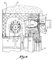
- the device When this operation, which is represented in FIG. 6, is carried out, the device is in the state of FIG. 7 in which it is noted that the wall 14 b of the inner sleeve 14 a , in the center of which was located the drilling barrel 14 a , has been cut by the saw 15 so as to provide in the spacer 12 an orifice 17 of dimensions adapted to the passage of a connecting rod and to the visual control of the positioning thereof, this orifice having identical dimensions to those of opening 6 a of partition 6.
- the veil 14b has dimensions perpendicular to the drilling axis of the saw 15 greater than those of the opening 17, so that part of it remains near the partition 6 in the state of the Figure 7. Indeed, the outer part of the web 14b constitutes an external flange relative to the sleeve 13, which serves, in one direction, as a stop against the sinking of the sleeve 14 inside the sleeve 13, and, in the other direction, of the bearing surface of the sleeve 14 against the partition 6.
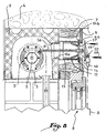
- a angle return plate 18 is fixed on the inner sleeve 14 through to the partition 6 by means of connecting screws 19, of so that this plate is firmly held in position whatever the mechanical properties of the partition 6 and especially if it is a weak material such as those who are generally employed for this function in the construction field.
- the invention makes it possible to firmly fix the plate 18 whatever the thickness of the partition 6 insofar as the screws 19 are tightened up to obtaining an effective fixing by pinching the partition 6 between the sleeve 14 and the plate 18.
- the plate 18 carries the connecting rod which has already been mentioned with reference to Figure 1 and which allows order the drive mechanism 9 from the crank 8, because it crosses the spacer 12 right through and connects the bevel gear 10 carried by the plate 18 to mechanism 9.
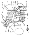
- Figure 9 is a perspective view which allows appreciate the relative position of the different elements when the device is in place.
- the spacer has a substantially square cross section, which, when the insulation material 7 is in place, creates a stop in rotation of the spacer 12 when a couple is applied by the hole saw during the drilling operation in Figure 6.
- FIG 10 there is illustrated another use of the spacer belonging to the invention in the case where the drive mechanism of the shaft 2 is provided with an electric motor.
- This electric motor must be supplied with electric current and the spacer of the invention can be used as a connection box insofar as it is provided with a lateral orifice 20 for passage of an electric cable 21.
- a cap 22 for closing the opening 6 a is provided to improve the aesthetic appearance of the device.
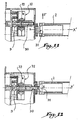
- a support axis 30 is movable between a retracted position visible in the figure 11 where it allows the displacement of the shaft 2 in one direction F perpendicular to the axis of rotation XX 'of the shaft 2 and a position visible in Figure 12 where it enters an orifice axial 31 of the shaft 2 so as to support the latter, that is to say to prevent its movements in one direction perpendicular to the XX 'axis, in particular under the effect of its own weight and that of the apron 3.
- the displacement of the axis 30 between its positions in FIGS. 11 and 12 is obtained by means an auxiliary winch 32 controlled by a rod 33 connected to a crank not shown.
- the shaft 2 and the deck 3 can be installed after installation of the box 1 in the wall and the positioning of the drive mechanism to one end of the box, as shown in Figure 2.
- the shaft 2 is rotated by the mechanism 9 to across the support axis 30.
- the two rods 10 and 33 can be selectively linked to a single crank 8, the crank being removed from the bevel gear 10 visible in Figure 1 for be mounted on a corresponding bevel gear, not shown, connected to the rod 33.
- the rod 33 also passes through the spacer 12 or an equivalent spacer.
Landscapes
- Engineering & Computer Science (AREA)
- Structural Engineering (AREA)
- Architecture (AREA)
- Civil Engineering (AREA)
- Operating, Guiding And Securing Of Roll- Type Closing Members (AREA)
- Feeding And Guiding Record Carriers (AREA)
- Curtains And Furnishings For Windows Or Doors (AREA)
- Spinning Or Twisting Of Yarns (AREA)
- Rolls And Other Rotary Bodies (AREA)
Description
- la figure 1 est un schéma de principe en coupe d'un mur comprenant une fenêtre équipée d'un volet roulant ;
- la figure 2 est une vue en coupe selon le plan II-II à la figure 1 ;
- la figure 3 est une vue de détail en coupe d'un dispositif d'entraínement de volet roulant conforme à l'invention lors d'une première étape de son installation ;
- la figure 4 est une figure analogue à la figure 3 lors d'une seconde étape d'installation ;
- la figure 5 est une vue analogue à la figure 3 lors d'une troisième étape d'installation ;
- la figure 6 est une vue analogue à la figure 3 lors d'une quatrième étape d'installation ;
- la figure 7 est une vue analogue à la figure 3 lors d'une cinquième étape d'installation ;
- la figure 8 est une vue analogue à la figure 3 lors d'une sixième étape d'installation ;
- la figure 9 est une vue partielle en perspective avec arrachement partiel du dispositif de l'invention en position montée ;
- la figure 10 est une vue analogue à la figure 3 du dispositif de l'invention utilisé avec un mécanisme d'entraínement à moteur électrique ;
- la figure 11 est une vue partielle en coupe d'un mécanisme d'entraínement et d'un arbre d'enroulement en cours de mise en place dans le plan de la figure 2 et
- la figure 12 est une vue analogue à la figure 11 alors que l'arbre d'enroulement est en position de travail.
Claims (12)
- Procédé d'installation d'un dispositif d'entraínement de volet roulant comprenant un arbre d'enroulement (2) logé dans un caisson (1) fixé dans un mur (4) dont une paroi est doublée d'une cloison d'habillage (6), caractérisé en qu'il consiste à monter, entre ledit caisson et ladite cloison, une entretoise (12) d'épaisseur variable et à fixer sur ladite entretoise, à travers ladite cloison, une platine (18) de renvoi d'angle (10) d'une manivelle (8) de commande d'un mécanisme d'entraínement (9) dudit volet roulant portant une tige de liaison (11) dudit renvoi d'angle audit mécanisme, ladite tige de liaison traversant ladite entretoise de part en part.
- Procédé d'installation selon la revendication 1, caractérisé en ce qu'il consiste à monter ladite entretoise (12) sur ledit caisson (1) avant la mise en place de ladite cloison (6) et à définir dans ladite cloison, lors de sa mise en place, une ouverture (6a) de façon à laisser dépasser un canon de perçage (14a) de ladite entretoise à l'extérieur de ladite cloison.
- Procédé d'installation selon la revendication 2, caractérisé en ce qu'il consiste à agrandir ladite ouverture (6a) par perçage au moyen d'un outil (15) centré sur ledit canon de perçage (14a), ledit perçage permettant de ménager, dans un voile (14b) de ladite entretoise situé à proximité de ladite cloison, un orifice (17) de dimensions adaptées au passage de ladite tige de liaison (11).
- Procédé d'installation selon l'une des revendications précédentes, caractérisé en ce qu'il consiste à insérer ledit arbre d'enroulement (2) dans ledit caisson (1) et à déplacer axialement un axe support (30) dudit arbre entre une position rétractée où il ne s'oppose pas au déplacement dudit arbre perpendiculairement (F) à son axe de rotation (XX') et une position déployée où il pénètre dans un orifice axial (31) dudit arbre de façon à le soutenir.
- Dispositif d'entraínement de volet roulant comprenant un arbre d'enroulement (2) logé dans un caisson (1) fixé dans un mur (4) dont une paroi est doublée d'une cloison d'habillage (6), caractérisé en ce qu'il comprend une entretoise (12) d'épaisseur variable fixée sur ledit caisson et disposée entre ledit caisson et ladite cloison, ladite entretoise s'étendant jusqu'au voisinage de ladite cloison, et une platine (18) de renvoi d'angle (10) d'une manivelle (8) de commande d'un mécanisme d'entraínement (9) dudit volet montée sur ladite entretoise et portant une tige de liaison (11) dudit renvoi d'angle audit mécanisme d'entraínement, ladite tige de liaison traversant ladite entretoise de part en part.
- Dispositif d'entraínement selon la revendication 5, caractérisé en que ladite entretoise (12) est formée de deux manchons (13,14) aptes à coulisser l'un dans l'autre.
- Dispositif d'entraínement selon la revendication 6, caractérisé en ce qu'un desdits manchons (14) comprend un voile (14b) de fond dont la partie centrale porte un canon de perçage (14a).
- Dispositif d'entraínement selon la revendication 6, caractérisé en ce qu'un desdits manchons (13) comprend une jupe (13a) apte à pénétrer dans un orifice (1a) dudit caisson.
- Dispositif d'entraínement selon la revendication 5, caractérisé en que ladite entretoise (12) est pourvue d'un orifice latéral (20) de passage d'un câble électrique (21).
- Dispositif d'entraínement selon la revendication 5, caractérisé en qu'il comprend un axe support (30) dudit arbre d'enroulement (2) mobile entre une position rétractée où il ne s'oppose pas au déplacement dudit arbre perpendiculairement (F) à son axe de rotation (XX') et une position déployée où il pénètre dans un orifice (31) dudit arbre de façon à le soutenir.
- Dispositif d'entraínement selon la revendication 10, caractérisé en ce qu'il comprend un treuil auxiliaire (32) de commande du déplacement dudit axe support (30) entre lesdites deux positions.
- Volet roulant comprenant un dispositif d'entraínement selon l'une des revendications 5 à 11.
Applications Claiming Priority (2)
| Application Number | Priority Date | Filing Date | Title |
|---|---|---|---|
| FR9610942A FR2752875B1 (fr) | 1996-09-03 | 1996-09-03 | Procede d'installation et dispositif d'entrainement de volet roulant et volet roulant comprenant un tel dispositif |
| FR9610942 | 1996-09-03 |
Publications (2)
| Publication Number | Publication Date |
|---|---|
| EP0826864A1 EP0826864A1 (fr) | 1998-03-04 |
| EP0826864B1 true EP0826864B1 (fr) | 2003-11-12 |
Family
ID=9495548
Family Applications (1)
| Application Number | Title | Priority Date | Filing Date |
|---|---|---|---|
| EP97420157A Expired - Lifetime EP0826864B1 (fr) | 1996-09-03 | 1997-09-02 | Procédé d'installation et dispositif d'entraínement de volet roulant et volet roulant comprenant un tel dispositif |
Country Status (5)
| Country | Link |
|---|---|
| EP (1) | EP0826864B1 (fr) |
| AT (1) | ATE254235T1 (fr) |
| DE (1) | DE69726074D1 (fr) |
| ES (1) | ES2115579T1 (fr) |
| FR (1) | FR2752875B1 (fr) |
Families Citing this family (3)
| Publication number | Priority date | Publication date | Assignee | Title |
|---|---|---|---|---|
| FR2920466B1 (fr) * | 2007-08-27 | 2009-12-18 | Deprat Jean | Mecanisme de commande manuelle de volet roulant |
| DE202011105763U1 (de) * | 2011-09-14 | 2012-12-17 | Maco Technologie Gmbh | Aufnahmekörper für Beschattungssysteme |
| FR2993308A1 (fr) * | 2012-07-11 | 2014-01-17 | Joseph Audureau | Ensemble comprenant un coffre tunnel et un coffre bois formant une reservation pour volet roulant |
Family Cites Families (1)
| Publication number | Priority date | Publication date | Assignee | Title |
|---|---|---|---|---|
| DE4329790C1 (de) * | 1993-09-03 | 1994-10-27 | Warema Renkhoff Gmbh & Co Kg | Behangelement, insbesondere Rolladen |
-
1996
- 1996-09-03 FR FR9610942A patent/FR2752875B1/fr not_active Expired - Fee Related
-
1997
- 1997-09-02 EP EP97420157A patent/EP0826864B1/fr not_active Expired - Lifetime
- 1997-09-02 ES ES97420157T patent/ES2115579T1/es active Pending
- 1997-09-02 DE DE69726074T patent/DE69726074D1/de not_active Expired - Lifetime
- 1997-09-02 AT AT97420157T patent/ATE254235T1/de not_active IP Right Cessation
Also Published As
| Publication number | Publication date |
|---|---|
| ES2115579T1 (es) | 1998-07-01 |
| EP0826864A1 (fr) | 1998-03-04 |
| FR2752875A1 (fr) | 1998-03-06 |
| DE69726074D1 (de) | 2003-12-18 |
| ATE254235T1 (de) | 2003-11-15 |
| FR2752875B1 (fr) | 1998-12-04 |
Similar Documents
| Publication | Publication Date | Title |
|---|---|---|
| EP2862259B1 (fr) | Dispositif motorise de manoeuvre destine a la manoeuvre d'un ecran mobile a toile enroulable d'un dispositif de couverture de fenetre ou d'ecran de projection | |
| EP1090788A1 (fr) | Ensemble comprenant une doublure intérieure de portière véhicule et un mécanisme lève-vitre fixé à cette doublure | |
| WO2017017047A1 (fr) | Motoréducteur polyvalent pour stores enroulables et stores non enroulables | |
| EP0826864A1 (fr) | Procédé d'installation et dispositif d'entraínement de volet roulant et volet roulant comprenant un tel dispositif | |
| EP0424294B1 (fr) | Panneau isolant à double vitrage avec dispositif motorisé d'écran interposé entre les deux parois transparentes | |
| EP0784145B1 (fr) | Volet roulant, destiné à protéger un ouvrant tel que notamment une fenêtre, porte ou similaire | |
| EP1160413A1 (fr) | Procédés de démontage et de remontage d'un bloc baie et d'un caisson, ensemble formé d'un bloc baie et d'un caisson et console d'extrémité d'un tel caisson | |
| FR2611798A1 (fr) | Dispositif pour la manoeuvre automatique des volets battants | |
| FR2591650A1 (fr) | Dispositif de manoeuvre pour volets ou persiennes a un ou deux vantaux pivotants | |
| EP3263816B1 (fr) | Fenêtre pour un bâtiment et installation domotique comprenant une telle fenêtre | |
| EP2186991A1 (fr) | Support de traversée de paroi pour dispositif de manoeuvre a manivelle | |
| WO2010004467A2 (fr) | Dispositif de maintien d'un treuil ou d'un moteur de volet roulant dans un coffre d'enroulement, treuil et coffre avec un tel dispositif | |
| FR2809761A1 (fr) | Dispositif formant support d'extremite pour un arbre d'enroulement, son procede d'assemblage et mecanisme de manoeuvre d'une installation de fermeture ou de protection solaire comprenant un tel dispositif | |
| FR2481351A1 (fr) | Dispositif d'actionnement, notamment pour portail | |
| EP2133505B1 (fr) | Dispositif de fermeture à tablier ou store repliable ou enroulable et à moteur d'entraînement électrique | |
| HK1215761B (en) | Motorised control device for controlling a mobile screen with windable canvas of a device for covering a window or projection screen | |
| FR2730002A3 (fr) | Dispositif de manivelle pour la manoeuvre manuelle des mecanismes d'envidage des stores, volets roulants et autres fermetures a enroulement | |
| EP1244199A1 (fr) | Moteur d'entrainement pour système de fermeture du type volet roulant | |
| EP2960400B1 (fr) | Installation de couverture de piscine avec un tambour enrouleur | |
| EP1231355A1 (fr) | Dispositif d'immobilisation d'un organe d'entraínement et mécanisme de manoeuvre d'une installation de fermeture ou de protection solaire comprenant un tel dispositif | |
| FR2487900A1 (fr) | Procede d'installation d'un chassis porte-fenetre dans son logement prevu dans l'ouverture de la maconnerie et les moyens de mise en oeuvre | |
| FR2661711A1 (fr) | Volet roulant, destine a proteger un ouvrant tel que fenetre, porte ou autre. | |
| EP1331355A1 (fr) | Dispositif destiné à bloquer le tube d'enroulement d'un volet roulant | |
| EP1445417A1 (fr) | Dispositif d'entraínement pour volet roulant | |
| EP1077303A1 (fr) | Système de volet comportant un volet roulant |
Legal Events
| Date | Code | Title | Description |
|---|---|---|---|
| PUAI | Public reference made under article 153(3) epc to a published international application that has entered the european phase |
Free format text: ORIGINAL CODE: 0009012 |
|
| AK | Designated contracting states |
Kind code of ref document: A1 Designated state(s): AT BE CH DE ES FR GB IT LI NL SE |
|
| AX | Request for extension of the european patent |
Free format text: AL;LT;LV;RO;SI |
|
| 17P | Request for examination filed |
Effective date: 19980429 |
|
| REG | Reference to a national code |
Ref country code: ES Ref legal event code: BA2A Ref document number: 2115579 Country of ref document: ES Kind code of ref document: T1 |
|
| AKX | Designation fees paid |
Free format text: AT BE CH DE ES FR GB IT LI NL SE |
|
| RBV | Designated contracting states (corrected) |
Designated state(s): AT BE CH DE ES FR GB IT LI NL SE |
|
| GRAH | Despatch of communication of intention to grant a patent |
Free format text: ORIGINAL CODE: EPIDOS IGRA |
|
| GRAH | Despatch of communication of intention to grant a patent |
Free format text: ORIGINAL CODE: EPIDOS IGRA |
|
| GRAA | (expected) grant |
Free format text: ORIGINAL CODE: 0009210 |
|
| AK | Designated contracting states |
Kind code of ref document: B1 Designated state(s): AT BE CH DE ES FR GB IT LI NL SE |
|
| PG25 | Lapsed in a contracting state [announced via postgrant information from national office to epo] |
Ref country code: NL Free format text: LAPSE BECAUSE OF FAILURE TO SUBMIT A TRANSLATION OF THE DESCRIPTION OR TO PAY THE FEE WITHIN THE PRESCRIBED TIME-LIMIT Effective date: 20031112 Ref country code: IT Free format text: LAPSE BECAUSE OF FAILURE TO SUBMIT A TRANSLATION OF THE DESCRIPTION OR TO PAY THE FEE WITHIN THE PRESCRIBED TIME-LIMIT;WARNING: LAPSES OF ITALIAN PATENTS WITH EFFECTIVE DATE BEFORE 2007 MAY HAVE OCCURRED AT ANY TIME BEFORE 2007. THE CORRECT EFFECTIVE DATE MAY BE DIFFERENT FROM THE ONE RECORDED. Effective date: 20031112 Ref country code: GB Free format text: LAPSE BECAUSE OF FAILURE TO SUBMIT A TRANSLATION OF THE DESCRIPTION OR TO PAY THE FEE WITHIN THE PRESCRIBED TIME-LIMIT Effective date: 20031112 Ref country code: AT Free format text: LAPSE BECAUSE OF FAILURE TO SUBMIT A TRANSLATION OF THE DESCRIPTION OR TO PAY THE FEE WITHIN THE PRESCRIBED TIME-LIMIT Effective date: 20031112 |
|
| REG | Reference to a national code |
Ref country code: GB Ref legal event code: FG4D Free format text: NOT ENGLISH |
|
| REG | Reference to a national code |
Ref country code: CH Ref legal event code: EP |
|
| REF | Corresponds to: |
Ref document number: 69726074 Country of ref document: DE Date of ref document: 20031218 Kind code of ref document: P |
|
| PG25 | Lapsed in a contracting state [announced via postgrant information from national office to epo] |
Ref country code: SE Free format text: LAPSE BECAUSE OF FAILURE TO SUBMIT A TRANSLATION OF THE DESCRIPTION OR TO PAY THE FEE WITHIN THE PRESCRIBED TIME-LIMIT Effective date: 20040212 |
|
| PG25 | Lapsed in a contracting state [announced via postgrant information from national office to epo] |
Ref country code: DE Free format text: LAPSE BECAUSE OF FAILURE TO SUBMIT A TRANSLATION OF THE DESCRIPTION OR TO PAY THE FEE WITHIN THE PRESCRIBED TIME-LIMIT Effective date: 20040213 |
|
| PG25 | Lapsed in a contracting state [announced via postgrant information from national office to epo] |
Ref country code: ES Free format text: LAPSE BECAUSE OF FAILURE TO SUBMIT A TRANSLATION OF THE DESCRIPTION OR TO PAY THE FEE WITHIN THE PRESCRIBED TIME-LIMIT Effective date: 20040223 |
|
| NLV1 | Nl: lapsed or annulled due to failure to fulfill the requirements of art. 29p and 29m of the patents act | ||
| GBV | Gb: ep patent (uk) treated as always having been void in accordance with gb section 77(7)/1977 [no translation filed] |
Effective date: 20031112 |
|
| PLBE | No opposition filed within time limit |
Free format text: ORIGINAL CODE: 0009261 |
|
| STAA | Information on the status of an ep patent application or granted ep patent |
Free format text: STATUS: NO OPPOSITION FILED WITHIN TIME LIMIT |
|
| PG25 | Lapsed in a contracting state [announced via postgrant information from national office to epo] |
Ref country code: LI Free format text: LAPSE BECAUSE OF NON-PAYMENT OF DUE FEES Effective date: 20040930 Ref country code: CH Free format text: LAPSE BECAUSE OF NON-PAYMENT OF DUE FEES Effective date: 20040930 Ref country code: BE Free format text: LAPSE BECAUSE OF NON-PAYMENT OF DUE FEES Effective date: 20040930 |
|
| 26N | No opposition filed |
Effective date: 20040813 |
|
| BERE | Be: lapsed |
Owner name: *SIMU Effective date: 20040930 |
|
| REG | Reference to a national code |
Ref country code: CH Ref legal event code: PL |
|
| PGFP | Annual fee paid to national office [announced via postgrant information from national office to epo] |
Ref country code: FR Payment date: 20060727 Year of fee payment: 10 |
|
| BERE | Be: lapsed |
Owner name: *SIMU Effective date: 20040930 |
|
| REG | Reference to a national code |
Ref country code: FR Ref legal event code: ST Effective date: 20080531 |
|
| PG25 | Lapsed in a contracting state [announced via postgrant information from national office to epo] |
Ref country code: FR Free format text: LAPSE BECAUSE OF NON-PAYMENT OF DUE FEES Effective date: 20071001 |