EP0826850A2 - Façade load-supporting means - Google Patents
Façade load-supporting means Download PDFInfo
- Publication number
- EP0826850A2 EP0826850A2 EP97113722A EP97113722A EP0826850A2 EP 0826850 A2 EP0826850 A2 EP 0826850A2 EP 97113722 A EP97113722 A EP 97113722A EP 97113722 A EP97113722 A EP 97113722A EP 0826850 A2 EP0826850 A2 EP 0826850A2
- Authority
- EP
- European Patent Office
- Prior art keywords
- support
- support profile
- wall
- arm
- holder
- Prior art date
- Legal status (The legal status is an assumption and is not a legal conclusion. Google has not performed a legal analysis and makes no representation as to the accuracy of the status listed.)
- Granted
Links
Images


Classifications
-
- E—FIXED CONSTRUCTIONS
- E04—BUILDING
- E04F—FINISHING WORK ON BUILDINGS, e.g. STAIRS, FLOORS
- E04F13/00—Coverings or linings, e.g. for walls or ceilings
- E04F13/07—Coverings or linings, e.g. for walls or ceilings composed of covering or lining elements; Sub-structures therefor; Fastening means therefor
- E04F13/08—Coverings or linings, e.g. for walls or ceilings composed of covering or lining elements; Sub-structures therefor; Fastening means therefor composed of a plurality of similar covering or lining elements
- E04F13/0801—Separate fastening elements
- E04F13/0803—Separate fastening elements with load-supporting elongated furring elements between wall and covering elements
- E04F13/0805—Separate fastening elements with load-supporting elongated furring elements between wall and covering elements with additional fastening elements between furring elements and the wall
- E04F13/0808—Separate fastening elements with load-supporting elongated furring elements between wall and covering elements with additional fastening elements between furring elements and the wall adjustable in several directions one of which is perpendicular to the wall
Definitions
- the invention relates to a facade substructure with at least one to be attached to a wall Wall bracket and at least one with a support profile connectable support profile holder.
- EP 0 348 853 B2 is a facade substructure known in which a wall bracket and a support profile holder juxtaposed with elongated holes and by a Screw are clamped together.
- On the support profile holder is designed with an eccentric closure Quick fastener fastened the support profile and clamped securely at the same time. To this Way the support profile is at a distance from the wall captured. Can on the vertical support profiles then facade panels are attached.
- the Elongated hole connection between wall bracket and support profile bracket is used to perform a depth adjustment can to the support profiles at a distance from the wall exactly to be able to align vertically.
- the wall distances of the support profiles vary widely, on the one hand in that the surface of the Building wall is not exactly vertical, and on the other hand in that the different wall distances of the Support profile holder can be specified. If the wall distance the support profiles are very large, arise for a long time Lever arms that act on the wall brackets. At very heavy facade panels and large wall clearance this means that the wall bracket to avoid leverage on the dowel must be very long. In addition comes that for static reasons the wall bracket and Support profile holder for different wall clearances and Facade loads of different strengths and dimensions must be available so that different types are available are that according to the respective facade to be chosen.
- the invention has for its object a facade substructure specify with which a wide range of wall clearances can be realized so that it is possible to strong the required variety of types to reduce.
- the facade substructure according to the invention has a swivel arm that is articulated at one end a wall bracket and articulated with one at the other end Support profile holder is connected and the change the distance of the support profile from the wall in different Swivel positions can be fixed. So that is it is possible to easily adjust the wall distance of the support profile Way to change in a relatively large area.
- the change in the swivel range thus takes place not by moving two holders with the help of one Slot connection, but by appropriate setting a swivel arm that can be moved around the wall bracket. This allows a relatively large distance range can be realized with the same adjustment mechanism, without different types of adjustment mechanisms required are.
- Another essential one is that the force of the swivel arm immediately and with a short lever arm on the wall bracket acts so that dowels that attach the wall bracket to the wall fix, almost exclusively due to the weight of the facade to be subjected to shear while in The longitudinal direction of the dowel almost only affects wind suction forces. It is therefore usually possible to use the wall bracket Plastic dowels to attach to the wall while otherwise very expensive heavy duty metal dowels required are.
- a support arm that engages with one on the Support profile to be attached support bracket is connected.
- the support arm forms together with the support bracket has a Y-shaped structure, the Carrying profile holder and the support holder on the one hand, that the support profile in the desired orientation is fixed, and on the other hand with their mutual Distance also the fixation of the swivel arm in the desired Cause swivel position.
- the Swivel arm also a support arm and this is articulated and height adjustable with the wall bracket or connected to an additional wall bracket.
- this case there is also a Y-shaped connection structure, which offers the advantages mentioned above, however, for the adjustment of the support bracket an additional effort in the form of a longer or additional wall bracket required.
- the connecting device can be designed that changes in length of the support profile, e.g. thermal Changes in length, are compensated for, with some of the Connecting devices as floating points and other than Fixed points are executed.
- some of the Connecting devices as floating points and other than Fixed points are executed.
- floating points and for Fixed points the same constructions can be used which can only be determined by the type of attachment or by the location of the engagement of a pin in an elongated hole, differentiate.
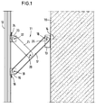
- a connecting device 11 mounted, which holds a support profile 12, the is vertically aligned at a distance from the wall 10.
- the connecting device has a wall holder 13 on, with dowels 14 directly on the front the wall 10 is attached, and a support profile holder 15, which with a clamping device 16 on the vertical Support profile 12 is attached. Between the holders 13, 15 extends a rigid swivel arm 17, the with the wall bracket 13 via a first joint 18 and with the support profile holder 15 via a second joint 19 is connected to the vertical hinge axis.
- a further joint 20 on which a support arm 21 engages.
- the other end of the support arm 21 is over a Joint 22 connected to a support profile holder 23, which engages with the support profile 12 and one Has clamping device 24 with which he on the support profile can be fixed immovably.
- the one from the Parts 13, 15, 17, 21 and 23 existing wall bracket forms a pre-assembled unit.
- the wall bracket 13 is first on the Wall 10 attached. Then the support profile holder 23rd and 15 brought into engagement with the support profile 12 and the clamping device 24 of the support holder 23 is tensioned, so that the support bracket 23 on the support profile 12th is fixed. Now the support profile 12 can be horizontal in Moved towards the wall 10 or in the opposite direction will. This movement is an exactly horizontal parallel movement, because the support arm 21 in the middle of the Length of the pivot arm 17 attacks and has a length which are equal to the length of one half of the swivel arm 17 is. When changing the distance of the support profile 12 of the wall 10 thus changes the height of the support profile 12 not. This change in distance slides the support profile holder 15 along the support profile 12.
- connection device 11 When the desired distance is reached, the Clamping device 16 tensioned and thereby the Y shape of the Connection device 11 fixed.
- mounting type is the connecting device 11 as a floating point - as opposed to a fixed point - educated.
- the axis of the joint 18 runs through a vertical slot 25, on the middle Height it is set.
- the wall bracket takes over 13 no vertical loads on the facade, but only horizontal forces.
- a fixed point at which the axis of the joint 18 at the lower end of the elongated hole 25 is arranged, for example at the upper end of the support profile 12. Through the sliding points are thermal changes in length of the facade balanced.
- the wall distance with which the support profile 12 is mounted is determined by the mutual distance in that of the support profile holder 15 and the support holder 23 from each other be fixed.
- FIG. 2 shows the connecting device 11 according to FIG. 1, the smallest possible wall clearance is set.
- the holders 15 and 23 have a relatively large size mutual distance. Wind pressure forces horizontal press against the facade in the direction of the wall 10, strive to keep the brackets 15,23 further apart to press, due to the geometric relationships large forces in the longitudinal direction of the support profile act on the holder.
- a spacer 26 provided in the minimum position of the connecting device presses against the support profile 12 and thereby further pressing apart the holders 15, 23 prevented.
- the spacer 26 is fixed here Body formed which adjusts along the pivot arm 17 can be. It is also possible to use a threaded rod to use in a thread of the swivel arm 17 is guided and with its end against the support profile presses.
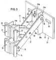
- Fig. 3 is a constructive embodiment of the connecting device 11 shown in detail.
- the swivel arm 17 here consists of two parallel supports 17a, 17b and the support arm 21 also consists of two parallel beams 21a, 21b.
- the wall bracket 13 has a base plate 27 in which two horizontal Elongated holes 28 for the fastening screws and two vertical webs 29a, 29b with the vertical elongated holes 25a, 25b are provided for the axes of the joint 18. This double structure of the webs makes the rigidity increased in the horizontal and vertical directions.
- the support profile holder 15 and the support holder 23 have Profile pieces 30,31 which engage with the support profile 12 can.
- the profile pieces 30 are designed that they are hooked to the side of the support profile can be scheduled so that they do not have the entire length of the support profile can be pushed on have to.
- the profile pieces are with the respective Clamping device 16 or 24 against removal from the Profile bar secured and you can by the clamping device also be jammed against longitudinal displacement.
- the clamping devices are eccentric clamping devices, as described in EP 0 348 853 B1.
- the profile strip also engages with the profile pieces together in a manner similar to that described in the EP patent is.
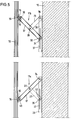
- FIG. 1 shows 4 shows a combination of a connecting device 11 of the type described with a connecting device 11a, which is mounted in the reverse manner, the Wall bracket 13 and the support bracket 23 at the same height are arranged below while the support profile holder 16 is arranged above. Even in this combination the connection devices for carrying the same Support profile 12 are used. 4 are additional the facade panels 12 in front of the support profile 33 recognizable.
- the attachment takes place in such a way that the Clamping devices 24 of the two support brackets 23 are clamped will. Then the wall distance of the support profile 12 brought to the desired level and finally are also the clamping devices 16 of the previous Wall bracket 15 which can be moved along the support profile tightened.
- connection devices 11b, 11c shown, the identical executed to each other, but in reverse Orientation are mounted.
- a Swivel arm 17 is provided which has a joint 34 with the wall bracket 35 and via a hinge 19 with the support profile holder 15 is connected. From a joint 20 in the support arm extends from the center of the swivel arm 17 21 to a hinge 36 of the wall bracket 35. Again the length of the support arm 21 is equal to the length of each the halves of the swivel arm 17.
- the joint 34 runs in a vertical longitudinal guide 37 of the wall bracket 35 and it is with a clamping device 38 for fixing in the set position Mistake.
- the hinge 36 is a hinge with a fixed axis. By adjusting the joint 34, the wall distance of the support profile 12 set.
- the joint 19 is here in an elongated hole of the support profile holder that is open at the bottom 15 guided to the floating point property of To enable connection device. At a fixed point the joint 19 would be at the upper end of the Slot 39.
- connection device 11c which is shown in Fig. 5 below is shown, the joint 34 with the swivel arm 17, which engages the wall bracket 35, a fixed joint.
- the joint is in the longitudinal guide 37 of the wall holder 36 of the support arm 21 out.
- This joint 36 is with a clamp 40 for clamping the position the joint 36 provided.
- each elongated wall bracket 35 for longitudinal guidance 37 has each an elongated wall bracket 35 for longitudinal guidance 37. It is of course also possible for the longitudinal guidance 37 to provide its own wall bracket.
- the connecting device can be provided with a Y structure. Rather, it can also have an X structure, for example one Scissor structure, the support arm 21 over the joint 20 is continued and on the wall bracket or the support profile is guided.
- an X structure for example one Scissor structure
Abstract
Description
Die Erfindung betrifft eine Fassadenunterkonstruktion mit mindestens einem an einer Wand zu befestigenden Wandhalter und mindestens einem mit einem Tragprofil verbindbaren Tragprofilhalter.The invention relates to a facade substructure with at least one to be attached to a wall Wall bracket and at least one with a support profile connectable support profile holder.
Aus EP 0 348 853 B2 ist eine Fassadenunterkonstruktion bekannt, bei der ein Wandhalter und ein Tragprofilhalter mit Langlöchern gegeneinandergesetzt und durch eine Schraube miteinander verspannt sind. An dem Tragprofilhalter wird mit einem als Exzenterverschluß ausgebildeten Schnellverschluß das Tragprofil befestigt und gleichzeitig verschiebungssicher festgeklemmt. Auf diese Weise wird das Tragprofil im Abstand von der Wand festgehalten. An den vertikalen Tragprofilen können anschließend Fassadenplatten befestigt werden. Die Langlochverbindung zwischen Wandhalter und Tragprofilhalter dient dazu, einen Tiefenausgleich durchführen Zu können, um die Tragprofile im Abstand von der Wand exakt vertikal ausrichten zu können. In der Praxis kommt es vor, daß die Wandabstände der Tragprofile stark variieren, einerseits dadurch, daß die Oberfläche der Gebäudewand nicht exakt vertikal verläuft, und andererseits dadurch, daß unterschiedliche Wandabstände der Tragprofilhalter vorgegeben werden. Wenn der Wandabstand der Tragprofile sehr groß ist, ergeben sich lange Hebelarme, die auf die Wandhalter wirken. Bei sehr schweren Fassadenplatten und großem Wandabstand führt dies dazu, daß die Wandhalter zur Vermeidung von Hebelkräften auf den Dübel sehr lang sein müssen. Hinzu kommt, daß aus statischen Gründen die Wandhalter und Tragprofilhalter für unterschiedliche Wandabstände und Fassadenlasten unterschiedlich stark und lang dimensioniert werden müssen, so daß unterschiedliche Tvpen verfügbar sind, die entsprechend der jeweiligen Fassade ausgewählt werden. Bei großen Lasten und großen Wandabständen werden Wandhalter benötigt, die wegen der erforderlichen Tragfähigkeit und Festigkeit ein sehr großes Gewicht haben müssen, wodurch die Kosten der Fassade beträchtlich erhöht werden. Da eine Langlochverbindung aber nur imstande ist, eine stark begrenzte Verschiebbarkeit des Tragprofilhalters in bezug auf den Wandhalter zu ermöglichen, sind zur Realisierung unterschiedlicher Wandabstände zahlreiche Typen von Wandhaltern erforderlich.EP 0 348 853 B2 is a facade substructure known in which a wall bracket and a support profile holder juxtaposed with elongated holes and by a Screw are clamped together. On the support profile holder is designed with an eccentric closure Quick fastener fastened the support profile and clamped securely at the same time. To this Way the support profile is at a distance from the wall captured. Can on the vertical support profiles then facade panels are attached. The Elongated hole connection between wall bracket and support profile bracket is used to perform a depth adjustment can to the support profiles at a distance from the wall exactly to be able to align vertically. In practice comes the wall distances of the support profiles vary widely, on the one hand in that the surface of the Building wall is not exactly vertical, and on the other hand in that the different wall distances of the Support profile holder can be specified. If the wall distance the support profiles are very large, arise for a long time Lever arms that act on the wall brackets. At very heavy facade panels and large wall clearance this means that the wall bracket to avoid leverage on the dowel must be very long. In addition comes that for static reasons the wall bracket and Support profile holder for different wall clearances and Facade loads of different strengths and dimensions must be available so that different types are available are that according to the respective facade to be chosen. With large loads and large wall clearances wall brackets are needed because of the required load capacity and strength a very must be heavy, which reduces the cost of Facade will be increased considerably. Because a slot connection but is only able to be a very limited one Slidability of the support profile holder in relation to the To allow wall brackets are different for realizing Wall clearances numerous types of wall brackets required.
Der Erfindung liegt die Aufgabe zugrunde, eine Fassadenunterkonstruktion anzugeben, mit der ein weiter Bereich von Wandabständen realisiert werden kann, so daß es möglich ist, die erforderliche Typenvielfalt stark zu reduzieren.The invention has for its object a facade substructure specify with which a wide range of wall clearances can be realized so that it is possible to strong the required variety of types to reduce.
Die Lösung dieser Aufgabe erfolgt erfindungsgemäß mit den im Patentanspruch 1 angegebenen Merkmalen. This object is achieved with the invention the features specified in claim 1.
Die erfindungsgemäße Fassadenunterkonstruktion weist einen Schwenkarm auf, der an einem Ende gelenkig mit einem Wandhalter und am anderen Ende gelenkig mit einem Tragprofilhalter verbunden ist und der zur Veränderung des Abstandes des Tragprofils von der Wand in unterschiedlichen Schwenkstellungen fixierbar ist. Damit ist es möglich, den Wandabstand des Tragprofiles auf einfache Weise in einem relativ großen Bereich zu verändern. Die Veränderung des Schwenkbereichs erfolgt also nicht durch Verschieben zweier Halter mit Hilfe einer Langlochverbindung, sondern durch entsprechende Einstellung eines um den Wandhalter bewegbaren Schwenkarms. Dadurch kann ein relativ großer Abstandsbereich mit Hilfe desselben Verstellmechanismus realisiert werden, ohne daß unterschiedliche Typen von Verstellmechanismen erforderlich sind. Ein weiterer wesentlicher Vorteil besteht darin, daß die Kraft des Schwenkarms unmittelbar und mit kurzem Hebelarm auf den Wandhalter einwirkt, so daß Dübel, die den Wandhalter an der Wand fixieren, durch das Eigengewicht der Fassade fast ausschließlich auf Scherung beansprucht werden, während in Dübellängsrichtung fast nur Windsogkräfte einwirken. Es ist daher in der Regel möglich, den Wandhalter mit Kunststoffdübeln an der Wand zu befestigen, während andernfalls sehr teure hochbelastbare Metalldübel erforderlich sind.The facade substructure according to the invention has a swivel arm that is articulated at one end a wall bracket and articulated with one at the other end Support profile holder is connected and the change the distance of the support profile from the wall in different Swivel positions can be fixed. So that is it is possible to easily adjust the wall distance of the support profile Way to change in a relatively large area. The change in the swivel range thus takes place not by moving two holders with the help of one Slot connection, but by appropriate setting a swivel arm that can be moved around the wall bracket. This allows a relatively large distance range can be realized with the same adjustment mechanism, without different types of adjustment mechanisms required are. Another essential one The advantage is that the force of the swivel arm immediately and with a short lever arm on the wall bracket acts so that dowels that attach the wall bracket to the wall fix, almost exclusively due to the weight of the facade to be subjected to shear while in The longitudinal direction of the dowel almost only affects wind suction forces. It is therefore usually possible to use the wall bracket Plastic dowels to attach to the wall while otherwise very expensive heavy duty metal dowels required are.
Ein weiterer Vorteil ergibt sich daraus, daß bei größeren Wandabständen das Gewicht der Haltevorrichtung wesentlich geringer ist als bei den üblichen Haltevorrichtungen, welche in diesem Fall Halter von sehr großer Wandstärke und hoher Lastaufnahmefähigkeit erfordern. Das geringere Gewicht hängt damit zusammen, daß der Schwenkarm durch die Last der Fassade nur zu einem Teil auf Biegung beansprucht wird, im übrigen aber wesentliche Belastungskomponenten als Druckkraft oder Zugkraft aufnimmt und überträgt.Another advantage arises from the fact that with larger Wall distances the weight of the holding device significantly is lower than with the usual holding devices, which in this case is very large Wall thickness and high load capacity are required. The lower weight is related to the fact that the swivel arm due to the load of the facade only one Part is claimed to bend, but otherwise essential Load components as compressive force or Takes up and transmits traction.
Vorzugsweise ist vorgesehen, daß an dem Schwenkarm gelenkig ein Stützarm angreift, der mit einem an dem Tragprofil zu befestigenden Stützhalter verbunden ist. Bei dieser Variante greifen an dem Tragprofil sowohl der Tragprofilhalter als auch der Stützhalter an, von denen jeder in Längsrichtung des Tragprofiles verstellbar und fixierbar ist. Der Stützarm bildet zusammen mit dem Stützhalter eine Y-förmige Struktur, wobei der Tragprofilhalter und der Stützhalter einerseits bewirken, daß das Tragprofil in der gewünschten Ausrichtung fixiert wird, und andererseits mit ihrem gegenseitigen Abstand auch die Fixierung des Schwenkarms in der gewünschten Schwenkstellung bewirken.It is preferably provided that articulated on the swivel arm a support arm that engages with one on the Support profile to be attached support bracket is connected. In this variant, both grip the support profile the support profile holder as well as the support holder from which each adjustable in the longitudinal direction of the support profile and is fixable. The support arm forms together with the support bracket has a Y-shaped structure, the Carrying profile holder and the support holder on the one hand, that the support profile in the desired orientation is fixed, and on the other hand with their mutual Distance also the fixation of the swivel arm in the desired Cause swivel position.
Bei einer alternativen Ausführungsform greift an dem Schwenkarm ebenfalls ein Stützarm an und dieser ist gelenkig und höhenverstellbar mit dem Wandhalter oder einem zusätzlichen Wandhalter verbunden. In diesem Fall entsteht ebenfalls eine Y-förmige Verbindungsstruktur, die die obengenannten Vorteile bietet, jedoch wird für den Verstellweg des Stützhalters ein zusätzlicher Aufwand in Form eines längeren oder zusätzlichen Wandhalters erforderlich.In an alternative embodiment, the Swivel arm also a support arm and this is articulated and height adjustable with the wall bracket or connected to an additional wall bracket. In this case there is also a Y-shaped connection structure, which offers the advantages mentioned above, however, for the adjustment of the support bracket an additional effort in the form of a longer or additional wall bracket required.
Die Verbindungsvorrichtung kann so ausgebildet sein, daß Längenänderungen des Tragprofils, z.B. thermische Längenänderungen, kompensiert werden, wobei einige der Verbindungsvorrichtungen als Gleitpunkte und andere als Festpunkte ausgeführt werden. Für Gleitpunkte und für Festpunkte sind die gleichen Konstruktionen verwendbar, die sich lediglich durch die Art ihrer Befestigung bzw. durch den Ort des Eingriffs eines Zapfens in ein Langloch, unterscheiden.The connecting device can be designed that changes in length of the support profile, e.g. thermal Changes in length, are compensated for, with some of the Connecting devices as floating points and other than Fixed points are executed. For floating points and for Fixed points the same constructions can be used which can only be determined by the type of attachment or by the location of the engagement of a pin in an elongated hole, differentiate.
Im folgenden werden unter Bezugnahme auf die Zeichnungen Ausführungsbeispiele der Erfindung näher erläutert.The following are with reference to the drawings Embodiments of the invention explained in more detail.
Es zeigen:
- Fig. 1
- eine Ansicht einer ersten Ausführungsform der Erfindung bei relativ weitem Wandabstand des Tragprofils,
- Fig. 2
- die Verbindungsvorrichtung nach Fig. 1 bei relativ engem Wandabstand des Tragprofils, mit zusätzlichem Abstandhalter,
- Fig. 3
- eine praktische Ausführung der Verbindungsvorrichtung in perspektivischer Darstellung,
- Fig. 4
- einen Vertikalschnitt durch eine Fassadenunterkonstruktion mit Verbindungsvorrichtungen der anhand der Fign. 1-3 beschriebenen Art und
- Fig. 5
- einen Vertikalschnitt durch eine andere Ausführungsform der Fassadenunterkonstruktion.
- Fig. 1
- 2 shows a view of a first embodiment of the invention with a relatively large wall distance of the support profile,
- Fig. 2
- 1 with a relatively narrow wall distance of the support profile, with an additional spacer,
- Fig. 3
- a practical embodiment of the connecting device in a perspective view,
- Fig. 4
- a vertical section through a facade substructure with connecting devices using the FIGS. 1-3 described type and
- Fig. 5
- a vertical section through another embodiment of the facade substructure.
Gemäß Fig. 1 ist an der Wand eines Gebäudes, die beispielsweise
aus Beton besteht, eine Verbindungsvorrichtung
11 montiert, welche ein Tragprofil 12 hält, das
mit Abstand von der Wand 10 vertikal ausgerichtet ist. 1 is on the wall of a building, for example
is made of concrete, a connecting
An der Frontseite (in Fig. 1 links) des Tragprofils 12
werden Fassadenplatten befestigt.On the front (on the left in FIG. 1) of the
Die Verbindungsvorrichtung weist einen Wandhalter 13
auf, der mit Dübeln 14 unmittelbar auf der Frontseite
der Wand 10 befestigt wird, sowie einen Tragprofilhalter
15, der mit einer Klemmvorrichtung 16 an dem vertikalen
Tragprofil 12 befestigt wird. Zwischen den Haltern
13,15 erstreckt sich ein starrer Schwenkarm 17,
der mit dem Wandhalter 13 über ein erstes Gelenk 18 und
mit dem Tragprofilhalter 15 über ein zweites Gelenk 19
mit vertikaler Gelenkachse verbunden ist.The connecting device has a
In der Mitte der Länge des Schwenkarms 17 befindet sich
ein weiteres Gelenk 20, an dem ein Stützarm 21 angreift.
Das andere Ende des Stützarmes 21 ist über ein
Gelenk 22 mit einem Tragprofilhalter 23 verbunden, welcher
mit dem Tragprofil 12 zusammengreift und eine
Klemmvorrichtung 24 aufweist, mit der er an dem Tragprofil
unverschiebbar fixiert werden kann. Der aus den
Teilen 13, 15, 17, 21 und 23 bestehende Wandhalter bildet
eine vormontierte Einheit.In the middle of the length of the
Bei der Montage wird zunächst der Wandhalter 13 an der
Wand 10 befestigt. Dann werden die Tragprofilhalter 23
und 15 in Eingriff mit dem Tragprofil 12 gebracht und
die Klemmvorrichtung 24 des Stützhalters 23 wird gespannt,
so daß der Stützhalter 23 an dem Tragprofil 12
fixiert ist. Nun kann das Tragprofil 12 horizontal in
Richtung auf die Wand 10 oder in Gegenrichtung bewegt
werden. Diese Bewegung ist eine exakt horizontale Parallelbewegung,
weil der Stützarm 21 in der Mitte der
Länge des Schwenkarmes 17 angreift und eine Länge hat,
die gleich der Länge einer Hälfte des Schwenkarmes 17
ist. Bei der Veränderung des Abstandes des Tragprofils
12 von der Wand 10 ändert sich somit die Höhe des Tragprofils
12 nicht. Bei dieser Abstandsveränderung gleitet
der Tragprofilhalter 15 entlang des Tragprofils 12.
Wenn der gewünschte Abstand erreicht ist, wird auch die
Klemmvorrichtung 16 gespannt und dadurch die Y-Form der
Verbindungsvorrichtung 11 fixiert. Bei der in Fig. 1
dargestellten Montageart ist die Verbindungsvorrichtung
11 als Gleitpunkt - im Gegensatz zu einem Festpunkt -
ausgebildet. Hierzu läuft die Achse des Gelenks 18
durch ein vertikales Langloch 25, auf dessen mittlere
Höhe sie eingestellt ist. Dadurch übernimmt der Wandhalter
13 keine Vertikalbelastungen der Fassade, sondern
nur horizontal wirkende Kräfte. Ein Fixpunkt, bei
dem die Achse des Gelenks 18 am unteren Ende des Langlochs
25 angeordnet ist, befindet sich beispielsweise
am oberen Ende des Tragprofiles 12. Durch die Gleitpunkte
werden thermische Längenänderungen der Fassade
ausgeglichen.During assembly, the
Der Wandabstand, mit dem das Tragprofil 12 montiert
wird, wird durch den gegenseitigen Abstand bestimmt, in
dem der Tragprofilhalter 15 und der Stützhalter 23 voneinander
fixiert werden.The wall distance with which the
Fig. 2 zeigt die Verbindungsvorrichtung 11 nach Fig. 1,
wobei der geringstmögliche Wandabstand eingestellt ist.
Die Halter 15 und 23 haben hierbei einen relativ großen
gegenseitigen Abstand. Winddruckkräfte, die horizontal
in Richtung auf die Wand 10 gegen die Fassade drücken,
sind bestrebt, die Halter 15,23 noch weiter auseinander
zu drücken, wobei aufgrund der geometrischen Verhältnisse
große Kräfte in Längsrichtung des Tragprofiles
auf die Halter wirken. Um zu verhindern, daß eine der
Klemmvorrichtungen 16,24 überlastet wird, ist an dem
Schwenkarm 17 (oder am Stützarm 21) ein Abstandhalter
26 vorgesehen, der in der Minimalstellung der Verbindungsvorrichtung
gegen das Tragprofil 12 drückt und
dadurch das weitere Auseinanderdrücken der Halter 15,23
verhindert. Der Abstandhalter 26 ist hier als fester
Körper ausgebildet, der längs des Schwenkarmes 17 verstellt
werden kann. Es ist auch möglich, eine Gewindestange
zu verwenden, die in einem Gewinde des Schwenkarms
17 geführt ist und mit ihrem Ende gegen das Tragprofil
drückt.FIG. 2 shows the connecting
In Fig. 3 ist eine konstruktive Ausführung der Verbindungsvorrichtung
11 in den Einzelheiten dargestellt.
Der Schwenkarm 17 besteht hier aus zwei parallelen Trägern
17a,17b und der Stützarm 21 besteht ebenfalls aus
zwei parallelen Trägern 21a,21b. Der Wandhalter 13
weist eine Basisplatte 27 auf, in der zwei horizontale
Langlöcher 28 für die Befestigungsschrauben sowie zwei
vertikale Stege 29a,29b mit den vertikalen Langlöchern
25a,25b für die Achsen des Gelenks 18 vorgesehen sind.
Durch diese Doppelstruktur der Stege wird die Steifigkeit
in horizontaler und vertikaler Richtung erhöht.In Fig. 3 is a constructive embodiment of the connecting
Der Tragprofilhalter 15 und der Stützhalter 23 weisen
Profilstücke 30,31 auf, die mit dem Tragprofil 12 zusammengreifen
können. Die Profilstücke 30 sind so ausgebildet,
daß sie unter Verhakung seitlich an das Tragprofil
angesetzt werden können, so daß sie nicht über
die gesamte Länge des Tragprofils aufgeschoben werden
müssen. Die Profilstücke werden mit der jeweiligen
Klemmvorrichtung 16 bzw. 24 gegen Entfernen von der
Profilleiste gesichert und sie können durch die Klemmvorrichtung
auch gegen Längsverschiebung verklemmt werden.
Die Klemmvorrichtungen sind Exzenter-Klemmvorrichtungen,
wie sie in EP 0 348 853 B1 beschrieben sind.
Auch die Profilleiste greift mit den Profilstücken in
ähnlicher Weise zusammen wie dies in dem EP-Patent beschrieben
ist.The
Während bei dem bisher beschriebenen Ausführungsbeispiel
der Wandhalter 13 und der Stützhalter 23 oben und
der Tragprofilhalter 15 unten angeordnet sind, zeigt
Fig. 4 eine Kombination einer Verbindungsvorrichtung 11
der beschriebenen Art mit einer Verbindungsvorrichtung
11a, die in umgekehrter Weise montiert ist, wobei der
Wandhalter 13 und der Stützhalter 23 auf gleicher Höhe
unten angeordnet sind, während der Tragprofilhalter 16
darüber angeordnet ist. Auch in dieser Kombination können
die Verbindungsvorrichtungen zum Tragen desselben
Tragprofils 12 benutzt werden. In Fig. 4 sind zusätzlich
die dem Tragprofil 12 vorgesetzten Fassadenplatten
33 erkennbar.While in the embodiment described so far
the
Die Befestigung erfolgt in der Weise, daß zuerst die
Klemmvorrichtungen 24 der beiden Stützhalter 23 festgeklemmt
werden. Danach wird der Wandabstand des Tragprofiles
12 auf das gewünschte Maß gebracht und schließlich
werden auch die Klemmvorrichtungen 16 der zuvor
längs des Tragprofiles verschiebbaren Wandhalter 15
festgespannt.The attachment takes place in such a way that the
Clamping
In Fig. 5 sind zwei andere Ausführungsformen von Verbindungsvorrichtungen
11b,11c dargestellt, die baugleich
zueinander ausgeführt, jedoch in umgekehrter
Orientierung montiert sind. Hierbei ist ebenfalls ein
Schwenkarm 17 vorgesehen, der über ein Gelenk 34 mit
dem Wandhalter 35 und über ein Gelenk 19 mit dem Tragprofilhalter
15 verbunden ist. Von einem Gelenk 20 in
der Mitte des Schwenkarmes 17 erstreckt sich der Stützarm
21 zu einem Gelenk 36 des Wandhalters 35. Auch hier
ist die Länge des Stützarms 21 gleich der Länge jeder
der Hälften des Schwenkarmes 17.In Fig. 5 are two other embodiments of
Das Gelenk 34 läuft in einer vertikalen Längsführung 37
des Wandhalters 35 und es ist mit einer Klemmvorrichtung
38 zur Fixierung in der eingestellten Position
versehen. Das Gelenk 36 ist ein Gelenk mit fester Achse.
Durch Einstellen des Gelenks 34 wird der Wandabstand
des Tragprofils 12 festgelegt. Das Gelenk 19 ist
hier in einem nach unten offenen Langloch des Tragprofilhalters
15 geführt, um die Gleitpunkteigenschaft der
Verbindungsvorrichtung zu ermöglichen. Bei einem Fixpunkt
befände sich das Gelenk 19 am oberen Ende des
Langlochs 39.The joint 34 runs in a vertical
Bei der Verbindungsvorrichtung 11c, die in Fig. 5 unten
dargestellt ist, ist das Gelenk 34 mit dem Schwenkarm
17, der an dem Wandhalter 35 angreift, ein Festgelenk.
In der Längsführung 37 des Wandhalters ist das Gelenk
36 des Stützarms 21 geführt. Dieses Gelenk 36 ist mit
einer Klemmvorrichtung 40 zum Festklemmen der Position
des Gelenks 36 versehen.In the
Die beiden Ausführungsformen nach Fig. 5 haben jeweils
einen langgestreckten Wandhalter 35 für die Längsführung
37. Es ist natürlich auch möglich, für die Längsführung
37 einen eigenen Wandhalter vorzusehen.5 have each
an
Abweichend von den beschriebenen Ausführungsbeispielen
ist es nicht erforderlich, die Verbindungsvorrichtung
mit einer Y-Struktur zu versehen. Sie kann vielmehr
auch eine X-Stuktur aufweisen, beispielsweise eine
Scherenstruktur, wobei der Stützarm 21 über das Gelenk
20 hinaus fortgesetzt ist und an dem Wandhalter bzw.
dem Tragprofil geführt wird.Deviating from the described exemplary embodiments
it is not necessary the connecting device
to be provided with a Y structure. Rather, it can
also have an X structure, for example one
Scissor structure, the
Claims (7)
dadurch gekennzeichnet,
daß der Wandhalter (13;35) und der Tragprofilhalter (15) jeweils gelenkig mit einem Schwenkarm (17) verbunden sind, welcher zur Veränderung des Abstandes des Tragprofiles (12) von der Wand (10) in unterschiedlichen Schwenkstellung fixierbar ist.Facade substructure with at least one wall holder (13; 35) to be fastened to a wall (10) and at least one support profile holder (15) which can be connected to the support profile (12),
characterized,
that the wall holder (13; 35) and the support profile holder (15) are each articulated to a swivel arm (17) which can be fixed in different pivot position to change the distance of the support profile (12) from the wall (10).
Applications Claiming Priority (2)
| Application Number | Priority Date | Filing Date | Title |
|---|---|---|---|
| DE29615166U | 1996-08-31 | ||
| DE29615166U DE29615166U1 (en) | 1996-08-31 | 1996-08-31 | Facade substructure |
Publications (3)
| Publication Number | Publication Date |
|---|---|
| EP0826850A2 true EP0826850A2 (en) | 1998-03-04 |
| EP0826850A3 EP0826850A3 (en) | 2000-08-23 |
| EP0826850B1 EP0826850B1 (en) | 2004-05-06 |
Family
ID=8028602
Family Applications (1)
| Application Number | Title | Priority Date | Filing Date |
|---|---|---|---|
| EP97113722A Expired - Lifetime EP0826850B1 (en) | 1996-08-31 | 1997-08-08 | Façade load-supporting means |
Country Status (2)
| Country | Link |
|---|---|
| EP (1) | EP0826850B1 (en) |
| DE (2) | DE29615166U1 (en) |
Cited By (1)
| Publication number | Priority date | Publication date | Assignee | Title |
|---|---|---|---|---|
| EP2610422A3 (en) * | 2011-11-28 | 2013-10-02 | BESSEY Tool GmbH & Co. KG | Spacer and frame or part of a frame |
Families Citing this family (7)
| Publication number | Priority date | Publication date | Assignee | Title |
|---|---|---|---|---|
| DE29704183U1 (en) * | 1997-03-07 | 1998-07-02 | Houben Dietmar | Hanging device for a facade substructure |
| NL1006110C2 (en) * | 1997-05-22 | 1998-11-25 | Hoogovens Aluminium Bausysteme | Movable holding element for plate-shaped building elements. |
| DE102014003675B4 (en) | 2014-03-14 | 2016-06-09 | Klaus Peter Abel | Facade fixing system |
| DE202016005362U1 (en) | 2016-09-05 | 2017-12-08 | Steffen Weiser | Facade construction unit |
| FR3057887B1 (en) * | 2016-10-24 | 2019-06-21 | Lorraine Industrie Bois | DEVICE AND METHOD FOR FASTENING A COVER PANEL ON A FASTENING FACADE |
| DE202020102247U1 (en) | 2020-04-22 | 2020-06-04 | SCHLÜHER M + K GmbH & Co.KG | Fastening device and facade construction herewith |
| WO2023147614A1 (en) | 2022-02-02 | 2023-08-10 | Arnold Peter | Installation and securing system for panels or discs on an underlying surface |
Citations (4)
| Publication number | Priority date | Publication date | Assignee | Title |
|---|---|---|---|---|
| DE1911070A1 (en) * | 1969-03-05 | 1970-10-08 | Kurz Hans Joachim | Fastening device for ventilated outer wall panels |
| EP0348853A2 (en) * | 1988-06-28 | 1990-01-03 | Dietmar Houben | Tightening device |
| EP0609631A1 (en) * | 1993-02-04 | 1994-08-10 | Rocamat S.A. | Setting and supporting device for facing plates |
| WO1996024732A1 (en) * | 1995-02-07 | 1996-08-15 | Manfred Hoffmann | Structure with a girder net held by spacers and facade ventilated at rear supported by said structure |
Family Cites Families (1)
| Publication number | Priority date | Publication date | Assignee | Title |
|---|---|---|---|---|
| DE2426080A1 (en) * | 1974-05-30 | 1975-12-18 | Blocher Kurt | Door, window or panel to fixed element attachment - incorporating interval -adjusting holder members attachable to each element |
-
1996
- 1996-08-31 DE DE29615166U patent/DE29615166U1/en not_active Expired - Lifetime
-
1997
- 1997-08-08 DE DE59711591T patent/DE59711591D1/en not_active Expired - Fee Related
- 1997-08-08 EP EP97113722A patent/EP0826850B1/en not_active Expired - Lifetime
Patent Citations (4)
| Publication number | Priority date | Publication date | Assignee | Title |
|---|---|---|---|---|
| DE1911070A1 (en) * | 1969-03-05 | 1970-10-08 | Kurz Hans Joachim | Fastening device for ventilated outer wall panels |
| EP0348853A2 (en) * | 1988-06-28 | 1990-01-03 | Dietmar Houben | Tightening device |
| EP0609631A1 (en) * | 1993-02-04 | 1994-08-10 | Rocamat S.A. | Setting and supporting device for facing plates |
| WO1996024732A1 (en) * | 1995-02-07 | 1996-08-15 | Manfred Hoffmann | Structure with a girder net held by spacers and facade ventilated at rear supported by said structure |
Cited By (1)
| Publication number | Priority date | Publication date | Assignee | Title |
|---|---|---|---|---|
| EP2610422A3 (en) * | 2011-11-28 | 2013-10-02 | BESSEY Tool GmbH & Co. KG | Spacer and frame or part of a frame |
Also Published As
| Publication number | Publication date |
|---|---|
| DE59711591D1 (en) | 2004-06-09 |
| EP0826850B1 (en) | 2004-05-06 |
| EP0826850A3 (en) | 2000-08-23 |
| DE29615166U1 (en) | 1996-10-17 |
Similar Documents
| Publication | Publication Date | Title |
|---|---|---|
| AT391407B (en) | FASTENING DEVICE FOR ADJUSTABLE FRONT PANELS OF DRAWERS | |
| EP0212228B1 (en) | Device for anchoring slabs | |
| AT5013U1 (en) | MOUNTING DEVICE FOR SETTING FASTENERS WHEN JOINING OVERLAPED BEAMS AT THEIR END | |
| DE4335387C2 (en) | Swing door for shower cabin | |
| EP0594962A1 (en) | Clamp for connecting edge-frame profiles of forming boards | |
| EP0826850B1 (en) | Façade load-supporting means | |
| EP1500768B1 (en) | Support and fixing device for door or window frames at the edge of wall openings | |
| DE2910325A1 (en) | Reusable building site guard-rail holder - has clamp with mutually movable jaws at base of support bar | |
| DE4108455C2 (en) | Mounting clamp for mounting a door frame of a door frame | |
| EP1439269B1 (en) | Bracket for mounting profiles for sanitary installations and frame with such a bracket | |
| DE8514233U1 (en) | Device for aligning formwork elements arranged side by side | |
| DE4205990C1 (en) | Clamp used in concrete shuttering - is tightened by wedge and has projections engaging groves in frame members | |
| DE4110185C1 (en) | ||
| EP0539672A1 (en) | Fitting for fixing in a two sided undercut groove of a member | |
| AT523350B1 (en) | Support element construction for a balcony railing and use of the same | |
| EP1485563A1 (en) | Supporting and guiding device for holding movable, hanging door or wall elements | |
| EP1126099A2 (en) | Fastening device for panel-like façade elements | |
| DE3517306C2 (en) | ||
| WO2022117645A1 (en) | Sliding door fitting, and method for installing a sliding door fitting | |
| EP1371788B1 (en) | Mounting frame for sanitary apparatuses | |
| EP1103348B1 (en) | Frames welding device | |
| EP0547438A1 (en) | One pin hinge | |
| DE2907116C2 (en) | Device for the assembly of a door frame | |
| DE3743701A1 (en) | Bracket anchor | |
| EP0393210B1 (en) | Adjustable dowel anchor for the concealed installation of facade elements |
Legal Events
| Date | Code | Title | Description |
|---|---|---|---|
| PUAI | Public reference made under article 153(3) epc to a published international application that has entered the european phase |
Free format text: ORIGINAL CODE: 0009012 |
|
| AK | Designated contracting states |
Kind code of ref document: A2 Designated state(s): BE CH DE FR GB IT LI NL |
|
| AX | Request for extension of the european patent |
Free format text: AL;LT;LV;RO;SI |
|
| PUAL | Search report despatched |
Free format text: ORIGINAL CODE: 0009013 |
|
| AK | Designated contracting states |
Kind code of ref document: A3 Designated state(s): AT BE CH DE DK ES FI FR GB GR IE IT LI LU MC NL PT SE |
|
| AX | Request for extension of the european patent |
Free format text: AL;LT;LV;RO;SI |
|
| 17P | Request for examination filed |
Effective date: 20010222 |
|
| AKX | Designation fees paid |
Free format text: BE CH DE FR GB IT LI NL |
|
| 17Q | First examination report despatched |
Effective date: 20030203 |
|
| GRAP | Despatch of communication of intention to grant a patent |
Free format text: ORIGINAL CODE: EPIDOSNIGR1 |
|
| GRAS | Grant fee paid |
Free format text: ORIGINAL CODE: EPIDOSNIGR3 |
|
| GRAA | (expected) grant |
Free format text: ORIGINAL CODE: 0009210 |
|
| AK | Designated contracting states |
Kind code of ref document: B1 Designated state(s): BE CH DE FR GB IT LI NL |
|
| PG25 | Lapsed in a contracting state [announced via postgrant information from national office to epo] |
Ref country code: NL Free format text: LAPSE BECAUSE OF FAILURE TO SUBMIT A TRANSLATION OF THE DESCRIPTION OR TO PAY THE FEE WITHIN THE PRESCRIBED TIME-LIMIT Effective date: 20040506 Ref country code: IT Free format text: LAPSE BECAUSE OF FAILURE TO SUBMIT A TRANSLATION OF THE DESCRIPTION OR TO PAY THE FEE WITHIN THE PRESCRIBED TIME-LIMIT;WARNING: LAPSES OF ITALIAN PATENTS WITH EFFECTIVE DATE BEFORE 2007 MAY HAVE OCCURRED AT ANY TIME BEFORE 2007. THE CORRECT EFFECTIVE DATE MAY BE DIFFERENT FROM THE ONE RECORDED. Effective date: 20040506 |
|
| REG | Reference to a national code |
Ref country code: GB Ref legal event code: FG4D Free format text: NOT ENGLISH |
|
| REG | Reference to a national code |
Ref country code: CH Ref legal event code: EP |
|
| REF | Corresponds to: |
Ref document number: 59711591 Country of ref document: DE Date of ref document: 20040609 Kind code of ref document: P |
|
| REG | Reference to a national code |
Ref country code: CH Ref legal event code: NV Representative=s name: ISLER & PEDRAZZINI AG |
|
| PGFP | Annual fee paid to national office [announced via postgrant information from national office to epo] |
Ref country code: GB Payment date: 20040805 Year of fee payment: 8 |
|
| PGFP | Annual fee paid to national office [announced via postgrant information from national office to epo] |
Ref country code: FR Payment date: 20040819 Year of fee payment: 8 |
|
| PGFP | Annual fee paid to national office [announced via postgrant information from national office to epo] |
Ref country code: CH Payment date: 20040824 Year of fee payment: 8 |
|
| PG25 | Lapsed in a contracting state [announced via postgrant information from national office to epo] |
Ref country code: BE Free format text: LAPSE BECAUSE OF NON-PAYMENT OF DUE FEES Effective date: 20040831 |
|
| GBT | Gb: translation of ep patent filed (gb section 77(6)(a)/1977) |
Effective date: 20040809 |
|
| NLV1 | Nl: lapsed or annulled due to failure to fulfill the requirements of art. 29p and 29m of the patents act | ||
| ET | Fr: translation filed | ||
| BERE | Be: lapsed |
Owner name: HOUBEN, DIETMAR Effective date: 20040831 |
|
| PLBE | No opposition filed within time limit |
Free format text: ORIGINAL CODE: 0009261 |
|
| STAA | Information on the status of an ep patent application or granted ep patent |
Free format text: STATUS: NO OPPOSITION FILED WITHIN TIME LIMIT |
|
| 26N | No opposition filed |
Effective date: 20050208 |
|
| PG25 | Lapsed in a contracting state [announced via postgrant information from national office to epo] |
Ref country code: GB Free format text: LAPSE BECAUSE OF NON-PAYMENT OF DUE FEES Effective date: 20050808 |
|
| PG25 | Lapsed in a contracting state [announced via postgrant information from national office to epo] |
Ref country code: LI Free format text: LAPSE BECAUSE OF NON-PAYMENT OF DUE FEES Effective date: 20050831 Ref country code: CH Free format text: LAPSE BECAUSE OF NON-PAYMENT OF DUE FEES Effective date: 20050831 |
|
| REG | Reference to a national code |
Ref country code: CH Ref legal event code: PL |
|
| GBPC | Gb: european patent ceased through non-payment of renewal fee |
Effective date: 20050808 |
|
| BERE | Be: lapsed |
Owner name: *HOUBEN DIETMAR Effective date: 20040831 |
|
| PG25 | Lapsed in a contracting state [announced via postgrant information from national office to epo] |
Ref country code: FR Free format text: LAPSE BECAUSE OF NON-PAYMENT OF DUE FEES Effective date: 20050831 |
|
| PGFP | Annual fee paid to national office [announced via postgrant information from national office to epo] |
Ref country code: DE Payment date: 20090227 Year of fee payment: 12 |
|
| PG25 | Lapsed in a contracting state [announced via postgrant information from national office to epo] |
Ref country code: DE Free format text: LAPSE BECAUSE OF NON-PAYMENT OF DUE FEES Effective date: 20100302 |
|
| REG | Reference to a national code |
Ref country code: FR Ref legal event code: ST Effective date: 20110218 |