EP0826357B1 - Support for a carrying or lifting device, particularly lifting device for patient - Google Patents
Support for a carrying or lifting device, particularly lifting device for patient Download PDFInfo
- Publication number
- EP0826357B1 EP0826357B1 EP97112825A EP97112825A EP0826357B1 EP 0826357 B1 EP0826357 B1 EP 0826357B1 EP 97112825 A EP97112825 A EP 97112825A EP 97112825 A EP97112825 A EP 97112825A EP 0826357 B1 EP0826357 B1 EP 0826357B1
- Authority
- EP
- European Patent Office
- Prior art keywords
- side walls
- wall part
- holder
- holder according
- wall
- Prior art date
- Legal status (The legal status is an assumption and is not a legal conclusion. Google has not performed a legal analysis and makes no representation as to the accuracy of the status listed.)
- Expired - Lifetime
Links
Images


Classifications
-
- A—HUMAN NECESSITIES
- A61—MEDICAL OR VETERINARY SCIENCE; HYGIENE
- A61G—TRANSPORT, PERSONAL CONVEYANCES, OR ACCOMMODATION SPECIALLY ADAPTED FOR PATIENTS OR DISABLED PERSONS; OPERATING TABLES OR CHAIRS; CHAIRS FOR DENTISTRY; FUNERAL DEVICES
- A61G7/00—Beds specially adapted for nursing; Devices for lifting patients or disabled persons
- A61G7/10—Devices for lifting patients or disabled persons, e.g. special adaptations of hoists thereto
- A61G7/1038—Manual lifting aids, e.g. frames or racks
-
- A—HUMAN NECESSITIES
- A61—MEDICAL OR VETERINARY SCIENCE; HYGIENE
- A61G—TRANSPORT, PERSONAL CONVEYANCES, OR ACCOMMODATION SPECIALLY ADAPTED FOR PATIENTS OR DISABLED PERSONS; OPERATING TABLES OR CHAIRS; CHAIRS FOR DENTISTRY; FUNERAL DEVICES
- A61G7/00—Beds specially adapted for nursing; Devices for lifting patients or disabled persons
- A61G7/05—Parts, details or accessories of beds
- A61G7/053—Aids for getting into, or out of, bed, e.g. steps, chairs, cane-like supports
- A61G7/0533—Lifting poles
-
- A—HUMAN NECESSITIES
- A61—MEDICAL OR VETERINARY SCIENCE; HYGIENE
- A61G—TRANSPORT, PERSONAL CONVEYANCES, OR ACCOMMODATION SPECIALLY ADAPTED FOR PATIENTS OR DISABLED PERSONS; OPERATING TABLES OR CHAIRS; CHAIRS FOR DENTISTRY; FUNERAL DEVICES
- A61G7/00—Beds specially adapted for nursing; Devices for lifting patients or disabled persons
- A61G7/10—Devices for lifting patients or disabled persons, e.g. special adaptations of hoists thereto
- A61G7/104—Devices carried or supported by
- A61G7/1044—Stationary fixed means, e.g. fixed to a surface or bed
Landscapes
- Health & Medical Sciences (AREA)
- Nursing (AREA)
- Life Sciences & Earth Sciences (AREA)
- Animal Behavior & Ethology (AREA)
- General Health & Medical Sciences (AREA)
- Public Health (AREA)
- Veterinary Medicine (AREA)
- Invalid Beds And Related Equipment (AREA)
- Forklifts And Lifting Vehicles (AREA)
- Load-Engaging Elements For Cranes (AREA)
Abstract
Description
Die Erfindung betrifft einen Halter für eine Trag- und/oder Hebevorrichtung für Patienten nach dem Oberbegriff des Anspruches 1.The invention relates to a holder for a carrying and / or lifting device for patients according to the preamble of claim 1.
Eine bekannte Trag- und/oder Hebevorrichtung für Patienten (BE 811 502) hat einen Halter mit zwei mit Abstand übereinander angeordneten Anschlußteilen, die an einer Wand des jeweiligen Aufstellraumes befestigt werden können. Der Halter nimmt ein Stützrohr der Tragvorrichtung auf. Mit den Anschlußteilen kann der Halter häufig nicht an jeder Wand, insbesondere nicht an Leichtbauwänden, befestigt werden. Die auf die Hebevorrichtung wirkenden, relativ hohen Kräfte können von einer Leichtbauwand nicht zuverlässig aufgenommen werden. In einem solchen Fall könnte zur Befestigung der Hebevorrichtung eine zwischen einem Boden und der Raumdecke eingespannte Stütze vorgesehen werden. Sie ist jedoch für abgehängte Decken nicht geeignet. Außerdem könnte sie beim Arbeiten mit der Hebevorrichtung deren Schwenkbewegung beeinträchtigen.A known carrying and / or lifting device for patients (BE 811 502) has a holder with two spaced one above the other Connection parts on a wall of the respective installation room can be attached. The holder takes a support tube the carrying device. With the connecting parts, the holder can often not attached to every wall, especially not to lightweight walls become. The relatively high acting on the lifting device Forces cannot be reliably absorbed by a lightweight wall become. In such a case, the lifting device could be attached one clamped between a floor and the ceiling Support should be provided. However, it is for suspended Blankets not suitable. In addition, when working with the Lifting device impair its pivoting movement.
Es wäre auch denkbar, durch aufwendig ausgebildete und anzuordnende Bodendeckenstreben oder durch am Boden mittels Platten angeflanschter Halter die Trag- und/oder Hebevorrichtung zu befestigen. Solche Vorrichtungen haben jedoch den Nachteil, daß sie beim Arbeiten mit dem Hebelift stören und außerdem relativ viel Platz beanspruchen. It would also be conceivable to use complex and trained ones Floor struts or by flanged to the floor with plates Holder to attach the carrying and / or lifting device. However, such devices have the disadvantage that they Interfering with the lift and also taking up a lot of space.
Eine andere bekannte Hebe- und/oder Tragvorrichtung (DE 8 613 814
U1) ist als frei auf dem Boden stehendes Gerät mit einer Bodenstütze
ausgebildet, die zwei V-förmig voneinander gerichtete und winklig
ausgebildete Füße aufweist.Another known lifting and / or carrying device (
Der Erfindung liegt die Aufgabe zugrunde, den gattungsgemäßen Halter so auszubilden, daß er bei möglichst geringem Platzbedarf die beim Einsatz der Trag- und/oder Hebevorrichtung auftretenden hohen Kräfte einwandfrei aufnehmen und den Boden und/oder eine Wand übertragen kann.The invention has for its object the generic Train the holder so that it takes up as little space as possible high occurring when using the carrying and / or lifting device Absorb forces properly and the floor and / or a wall can transmit.
Diese Aufgabe wird beim gattungsgemäßen Halter erfindungsgemäß mit den kennzeichnenden Merkmalen des Anspruches 1 gelöst.This object is achieved according to the invention in the generic holder solved with the characterizing features of claim 1.
Der erfindungsgemäße Halter ist als Ständer ausgebildet, der auf dem Boden infolge seiner beiden mit Abstand voneinander angeordneten und plattenartig ausgebildeten Füße einen sicheren Stand hat. Der Halter kann infolge dieser Ausbildung sowohl frei im Raum stehen, aber auch aus Platzgründen an einer Wand befestigt sein. Hierzu wird sein Wandteil an der Wand befestigt. Dabei ist der Halter mit den plattenartigen Füßen auf dem Boden abgestützt. Die Hebeund/oder Tragvorrichtung läßt sich einfach und schnell am Halter sichern. Die auf die Hebe- und/oder Tragvorrichtung wirkenden relativ hohen Kräfte werden über die Ständerfüße einwandfrei auf den Boden übertragen, so daß selbst bei einer Befestigung des Ständers an einer Leichtbauwand auf diese Wand keine übermäßigen Kräfte wirken. Der erfindungsgemäße Halter läßt sich somit problemlos an beliebigen Orten einsetzen und befestigen, ohne daß hierfür auf bauliche Besonderheiten, wie auf eine Leichtbauweise, Rücksicht genommen werden muß. Die Hebe- und/oder Tragvorrichtung kann in montierter Lage am Halter bzw. Ständer ohne weiteres in die gewünschte Position verschwenkt werden, so daß ein ungestörtes Arbeiten gewährleistet ist. Schließlich nimmt der Ständer auch relativ wenig Raum in Anspruch. währleistet ist. Schließlich nimmt der Ständer auch relativ wenig Raum in Anspruch.The holder according to the invention is designed as a stand on the floor as a result of its two spaced apart and plate-like feet have a secure footing. As a result of this training, the holder can both stand freely in the room, but also be attached to a wall for reasons of space. For this his wall part is attached to the wall. The holder is with the plate-like feet supported on the floor. The lifting and / or The carrying device can be easily and quickly secured to the holder. Relative to the lifting and / or carrying device high forces are impeccably on the floor via the stand feet transferred so that even when attaching the stand to a lightweight wall does not exert excessive forces on this wall. The holder according to the invention can thus be easily on any Use places and fasten without building Special features, such as a lightweight construction, are taken into account must become. The lifting and / or carrying device can be assembled Position on the holder or stand easily in the desired Position swiveled so that undisturbed work is guaranteed is. Finally, the stand takes relatively little Space required. is guaranteed. Finally, the stand also takes a relative takes up little space.
Weitere Merkmale der Erfindung ergeben sich aus den weiteren Ansprüchen, der Beschreibung und den Zeichnungen.Further features of the invention result from the others Claims, the description and the drawings.
Die Erfindung wird nachstehend anhand eines in den Zeichnungen dargestellten Ausführungsbeispieles näher beschrieben. Es zeigt:
- Fig. 1
- einen erfindungsgemäßen, als Ständer ausgebildeten Halter in perspektivischer Darstellung,
- Fig. 2
- den Ständer nach Fig. 1 in Vorderansicht,
- Fig. 3
- den Ständer nach Fig. 1 in Draufsicht und in vergrößerter Darstellung,
- Fig. 4
- den Ständer nach Fig. 1 in Seitenansicht gemäß Pfeil IV in Fig. 1,
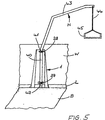
- Fig. 5
- in vereinfachter Darstellung den erfindungsgemäßen Halter mit einem daran angeordneten Patientenhebelift.
- Fig. 1
- a holder according to the invention, designed as a stand, in a perspective view,
- Fig. 2
- 1 in the front view,
- Fig. 3
- 1 in top view and in an enlarged view,
- Fig. 4
- 1 in side view according to arrow IV in Fig. 1,
- Fig. 5
- in a simplified representation the holder according to the invention with a patient lever lift arranged thereon.
Der Halter 1 nach den Fig. 1 bis 5 dient vorzugsweise zum Befestigen einer Hebevorrichtung H für Patienten, einem sogenannten Patientenlift (Fig. 5). Der Halter 1 ist als Ständer ausgebildet, der freistehend auf einem Boden B befestigt werden kann. Der Ständer 1 kann aber auch stehend an einer Wand W befestigt sein. Es ist aber auch möglich, den Halter H am Boden B und an der Wand W zu befestigen, wodurch eine optimale Abstützung des Halters H erreicht wird. The holder 1 according to FIGS. 1 to 5 is preferably used for attaching a lifting device H for patients, a so-called patient lift (Fig. 5). The holder 1 is designed as a stand that is free-standing on a Floor B can be attached. The stand 1 can also be attached to a wall W standing. But it is also possible, the holder H on the floor B and on the wall W to attach, thereby providing optimal support for the holder H is reached.
Der Halter 1 hat eine rechteckige Rückwand 2 sowie über
diese seitlich vorstehende Seitenwände 3 und 4, die die
Ständerfüße 5, 6 aufweisen. Hierzu sind die unteren Enden
der Seitenwände 3, 4 rechtwinklig nach außen abgebogen.
Der Halter 1 ist spiegelsymmetrisch zu seiner Vertikalmittelebene
ausgebildet. Die Seitenwände 3, 4 haben
etwa dreieckförmigen Umriß; sie sind vorzugsweise einteilig
mit der Rückwand 2 ausgebildet. Die oberen Ränder
7, 8 der nach oben spitz zulaufenden Seitenwände 3, 4
liegen auf gleicher Höhe wie der obere Rand 9 der Rückwand
2. Die Breite der unteren Ränder 10, 11 der Seitenwände
3, 4 ist größer als die Breite der Rückwand 2
(Fig. 1, 3). Die Füße 5, 6 haben etwa trapezförmigen Umriß,
derart, daß die freien Längsränder der Füße 5, 6
kürzer sind als ihre an die Seitenwände 3, 4 anschließenden
Ränder.The holder 1 has a rectangular
Die Rückwand 2 und die Seitenwände 3, 4 weisen jeweils
eine an ihrem unteren Rand 9', 10, 11 vorgesehene Aussparung
12 bis 14 auf. Die Aussparung 12 der Rückwand 2
erstreckt sich über deren ganze Breite, während die Aussparungen
13, 14 nur geringe Breite haben und sich von
der Rückwand 2 aus nur über einen kleinen Teil der Breite
der Seitenwände 3, 4 erstrecken. Die Aussparungen 12
haben gleiche Höhe und begrenzen eine Ständeröffnung 12
bis 14. Liegt der Halter 1 mit seiner Rückwand 2 an der
Wand W an, dann kann durch die Aussparungen 12 bis 14
beispielsweise eine am unteren Wandende befestigte Bodenleiste
L (Fig. 5) sich erstrecken, so daß der Halter
1 trotz der über die Wand W vorstehenden Bodenleiste L
einwandfrei mit seiner Rückwand 2 an der Wand W anliegen
kann und eine hohe Standsicherheit hat. The
Wie Fig. 3 zeigt, liegen die Seitenwände 3, 4 unter einem
stumpfen Winkel zur Rückwand 2, von der aus die Seitenwände
3, 4 divergierend zueinander unter jeweils
gleichem Winkel verlaufen. Aufgrund der Aussparungen 13,
14 haben die Füße 5, 6 Abstand von der Rückwand 2 (Fig.
3). Die von der Rückwand 2 abgewandten freien Ränder 15,
16 der Füße 5, 6 verlaufen senkrecht zu den Seitenwänden
3, 4, während die gegenüberliegenden Ränder 15', 16' spitzwinklig
zu den Seitenwänden 3 bzw. 4 verlaufen. Mit relativ
geringem Abstand benachbart zu den Rändern 15, 15'
bzw. 16, 16' weisen die Füße 5, 6 Durchstecköffnungen 17,
18 und 19, 20 für Sicherungsteile, wie Schrauben und
dergleichen, auf, mit denen der mit den Füßen 5, 6 flächig
auf dem Boden B aufliegende Halter 1 auf dem Boden
B befestigt werden kann. Der Halter 1 kann sowohl frei
im Raum als auch mit seiner Rückwand 2 an der Wand W
ganzflächig anliegend montiert werden. In diesem Fall
ist der Halter 1 vorteilhaft über weitere Befestigungsteile
auch an der Wand befestigt. Sie werden durch Öffnungen
21 bis 26 in der Rückwand 2 gesteckt bzw. geschraubt.
Vorteilhaft sind, wie Fig. 2 zeigt, mit geringem
Abstand vom oberen und unteren Rand 9 bzw. 12 der
Rückwand 2 jeweils zwei auf gleicher Höhe vorgesehene
Öffnungen 21, 22 und 23, 24 vorgesehen. In halber Höhe
der Wand 2 sind zwei zusätzliche Öffnungen 25 und 26
vorhanden. Mit Abstand oberhalb der Öffnungen 23 und 24
und mit Abstand unterhalb der Öffnungen 21 und 22 weist
die Rückwand 2 im Bereich zwischen den Seitenwänden 3, 4
Anschlußteile 27 und 28 auf, die, wie die Fig. 2 und 3
zeigen, jeweils eine schwalbenschwanzförmige Öffnung 29,
30 aufweisen. Diese Öffnungen dienen zur Aufnahme eines
entsprechenden (nicht näher dargestellten) Gegenstückes
41, 42 (Fig. 5) des am Halter 1 zu sichernden Hebeliftes
H. Die Anschlußteile 27 und 28 liegen mit relativ geringem
Abstand von den Öffnungen 21, 22 bzw. 23, 24, jedoch
mit relativ großem Abstand von den mittleren Öffnungen
25, 26. Dadurch sind für den Hebelift H relativ weit
auseinander liegende Befestigungsstellen geschaffen, so
daß er einen sicheren Halt am Ständer 1 hat.3 shows, the
Die Anschlußstücke 27, 28 sind an der Rückwand 2 vorteilhaft
lösbar befestigt und liegen mit einem Fußstück
32, 33 an der Rückwand 2 an. Von den Fußstücken 32, 33
stehen Endstücke 34, 35; 36, 37 vor, deren einander zugewandte
Ränder 38, 39 vom Fußstück 32, 33 aus konvergierend
verlaufen und die Seitenflächen der Schwalbenschwanzförmigen
Öffnungen 29, 30 begrenzen.The
Der Halter 1 weist infolge seiner gegenüber der Rückwand
2 nach außen verlaufenden Seitenwände 3, 4 und den Füßen
5, 6 eine hohe Standsicherheit auf. Er ist infolge dieser
Ausbildung an relativ weit auseinander liegenden
Stellen auf dem Boden B abgestützt. Eine zusätzliche Anlage
und Befestigung an der Wand W gewährleistet einen
noch sichereren Halt der Hebevorrichtung H. Mit Hilfe
des Halters 1 kann die Hebevorrichtung H ohne weiteres
auch an einer Leichtbauwand befestigt werden. In diesem
Fall überträgt der Halter die bei Belastung der Hebevorrichtung
H auftretenden Kräfte über die Seitenwände 3, 4
und deren Füße 5, 6 einwandfrei auf den Boden. Auch wenn
der Halter 1 freistehend auf dem Boden B montiert ist,
kann er die auf die Hebevorrichtung wirkenden relativ
hohen Kräfte einwandfrei aufnehmen und auf den Boden
übertragen. Die im Halter 1 angeordnete Hebevorrichtung
H (Fig. 5) kann ohne weiteres um 180° geschwenkt werden,
da über die Seitenwände 3, 4 bzw. die Füße 5, 6 die Last
über den gesamten Schwenkbereich einwandfrei abgestützt
wird. Im Halter 1 ist die Hebevorrichtung H geschützt
untergebracht, wobei der Halter nur relativ wenig Platz
in Anspruch nimmt.The holder 1 has due to its opposite the
Die Hebevorrichtung H hat einen Ständer 40 (Fig. 5), an
dem die Gegenstücke 41, 42 befestigt sind, die in montierter
Lage der Hebevorrichtung H in die Schwalbenschwanzförmigen
Öffnungen 29, 30 der Anschlußteile 27,
28 eingreifen. Der Ständer 40 steht auf dem Boden B auf
und geht am oberen Ende in einen galgenförmigen Tragarm
43 über, an dem über ein Seil 44 oder dergleichen ein
Griff 45 befestigt ist. Das Seil 44 kann auch im oder
längs des Tragarms 43 und des Ständers 40 zu einer Aufwickeltrommel
geführt sein, so daß das Seil 44 zur Verstellung
des Griffes 45 auf- oder abgewickelt werden
kann. Der Ständer 40 ist in den Gegenstücken 41, 42
drehbar angeordnet, so daß er im erforderlichen Maße gedreht
werden kann.The lifting device H has a stand 40 (FIG. 5)
which the
Claims (11)
- Holder (1) for a support and/or lifting device for patients, with at least one connecting part (27, 28) to be fixed to a wall (W) or of the like and a reception opening for the lifting device (H),
characterised in that the holder (1) is formed as a column with two plate-like feet (5, 6) standing on the floor (B) at a distance from each other and at least one wall part (2) for contact to and support at a wall (W) and in that the feet (5, 6) are formed by a bent up edge of the side walls (3, 4) of the holder (1). - Holder according to claim 1,
characterised in that the feet (5, 6) are bent-up transversely, advantageously at right angles to the side walls (3, 4). - Holder according to claim 1 or 2,
characterised in that at least one side wall, preferably both side walls (3, 4) include an obtuse angle with the preferably rectangular wall part (2). - Holder according to one of the claims 1 to 3,
characterised in that the side walls (3, 4) have the same, approximately triangular outline and preferably tapered in an upward direction. - Holder according to one of the claims 1 to 4,
characterised in that the side walls (3, 4) have upper edges (7, 8) which are on a common, preferably horizontal plane with an upper edge of the wall part (2) and that advantageously the upper edges (7, 8) of the side walls (3, 4) adjoin the upper edge (9) of the wall part (2). - Holder according to one of the claims 1 to 5,
characterised in that the greatest width of the side walls (3, 4) provided in the zone of the lower edges (10, 11) is larger than the width of the wall part (2). - Holder according to one of the claims 1 to 6,
characterised in that the wall part (2) and/or the side walls (3, 4) comprise a recess (12 to 14), provided each at their lower edge (9', 10, 11). - Holder according to claim 7,
characterised in that the recess (12) in the wall part (2) extends over its whole width. - Holder according to claim 7 or 8,
characterised in that the recesses (13, 14) of the side walls (3, 4) are narrower than the recess (12) of the wall part (2). - Holder according to one of the claims 1 to 9,
characterised in that at least the feet (5, 6), preferably the feet and the wall part (2) comprise openings (15 to 18; 21 to 26) for mounting parts such as screws and the like. - Holder according to one of the claims 1 to 10,
characterised in that the wall part (2) comprises two connecting parts (27, 28), located at a certain distance one over the other for a coupling component of the support device (H), the two connecting parts preferably to be detachably fixed to the wall part (2), preferably screwed.
Applications Claiming Priority (2)
| Application Number | Priority Date | Filing Date | Title |
|---|---|---|---|
| DE29615004U | 1996-08-29 | ||
| DE29615004U DE29615004U1 (en) | 1996-08-29 | 1996-08-29 | Holder for a carrying and / or lifting device, in particular a lifting device for patients |
Publications (2)
| Publication Number | Publication Date |
|---|---|
| EP0826357A1 EP0826357A1 (en) | 1998-03-04 |
| EP0826357B1 true EP0826357B1 (en) | 2002-12-04 |
Family
ID=8028492
Family Applications (1)
| Application Number | Title | Priority Date | Filing Date |
|---|---|---|---|
| EP97112825A Expired - Lifetime EP0826357B1 (en) | 1996-08-29 | 1997-07-25 | Support for a carrying or lifting device, particularly lifting device for patient |
Country Status (3)
| Country | Link |
|---|---|
| EP (1) | EP0826357B1 (en) |
| AT (1) | ATE228812T1 (en) |
| DE (2) | DE29615004U1 (en) |
Family Cites Families (3)
| Publication number | Priority date | Publication date | Assignee | Title |
|---|---|---|---|---|
| BE811502A (en) * | 1974-02-25 | 1974-06-17 | ORTHOPEDIC SENSITIVER FOR WALL MOUNTING | |
| DE8613814U1 (en) * | 1986-05-22 | 1986-08-14 | Meinhardt, Werner, Dipl.-Ing., 2087 Hasloh | Holding frame |
| DE29614203U1 (en) * | 1996-08-16 | 1996-10-24 | Cavelius Stefan | Fixing bar for exercise bands |
-
1996
- 1996-08-29 DE DE29615004U patent/DE29615004U1/en not_active Expired - Lifetime
-
1997
- 1997-07-25 DE DE59708868T patent/DE59708868D1/en not_active Expired - Fee Related
- 1997-07-25 EP EP97112825A patent/EP0826357B1/en not_active Expired - Lifetime
- 1997-07-25 AT AT97112825T patent/ATE228812T1/en not_active IP Right Cessation
Also Published As
| Publication number | Publication date |
|---|---|
| DE59708868D1 (en) | 2003-01-16 |
| ATE228812T1 (en) | 2002-12-15 |
| EP0826357A1 (en) | 1998-03-04 |
| DE29615004U1 (en) | 1996-10-24 |
Similar Documents
| Publication | Publication Date | Title |
|---|---|---|
| WO2007071765A1 (en) | Shelf system comprising a support element that is infinitely adjustable in a wall rail | |
| EP0447822B1 (en) | Livestock cubicle | |
| DE3409992A1 (en) | Device for suspending a false ceiling | |
| EP0826357B1 (en) | Support for a carrying or lifting device, particularly lifting device for patient | |
| DE2921636A1 (en) | Universal building wall climbing appliance - has guide-rail top swivelling mounting, hoist support bracket and adjustable base support | |
| DE4109374C1 (en) | ||
| DE1297399B (en) | Suspension device for animal cages | |
| DE3121869A1 (en) | HOLDING CONSOLE FOR DETACHABLE OBJECT ATTACHMENT TO A WALL RAIL | |
| EP0331976A1 (en) | Apparatus stand | |
| DE10210778B4 (en) | Housing or frame with a cable routing device | |
| DE7822671U1 (en) | Transport device for sports equipment | |
| DE20220848U1 (en) | Housing or framework for supporting and guiding glass optical fiber cables, has metal plates with D-shaped guide members | |
| DE2544013A1 (en) | Adjustable angle shelf support for magazine or book shelves - has support arm pivoting on carrier plate with corresponding holes in each to provide angle adjustment | |
| DE2261036C3 (en) | Arrangement on work tables for setting up devices | |
| DE102017117977B3 (en) | wall hooks | |
| DE3321419C2 (en) | ||
| EP0405228B1 (en) | Fixation device for demountable seats or supporting means for seats for grandstands | |
| DE3201999C2 (en) | Device for hanging up elongated objects | |
| DE3111806C2 (en) | Holding device for flat, long objects, especially for a sailing board | |
| AT226404B (en) | Boom construction | |
| DE202022100412U1 (en) | flower box | |
| DE8209713U1 (en) | Label holders for nameplates or other identifications, especially in power plants | |
| CH717130A1 (en) | Suspension device and primary carrier for the presentation of objects. | |
| DE8108794U1 (en) | "HOLDING DEVICE, IN PARTICULAR FOR A WINDSURFBOARD" | |
| DE102009044577B4 (en) | Camera carriage and footplate element |
Legal Events
| Date | Code | Title | Description |
|---|---|---|---|
| PUAI | Public reference made under article 153(3) epc to a published international application that has entered the european phase |
Free format text: ORIGINAL CODE: 0009012 |
|
| AK | Designated contracting states |
Kind code of ref document: A1 Designated state(s): AT BE CH DE DK FI FR GB IT LI SE |
|
| 17P | Request for examination filed |
Effective date: 19980609 |
|
| AKX | Designation fees paid |
Free format text: AT BE CH DE DK FI FR GB IT LI SE |
|
| RBV | Designated contracting states (corrected) |
Designated state(s): AT BE CH DE DK FI FR GB IT LI SE |
|
| 17Q | First examination report despatched |
Effective date: 20010115 |
|
| GRAG | Despatch of communication of intention to grant |
Free format text: ORIGINAL CODE: EPIDOS AGRA |
|
| GRAG | Despatch of communication of intention to grant |
Free format text: ORIGINAL CODE: EPIDOS AGRA |
|
| GRAH | Despatch of communication of intention to grant a patent |
Free format text: ORIGINAL CODE: EPIDOS IGRA |
|
| RAP1 | Party data changed (applicant data changed or rights of an application transferred) |
Owner name: AACURAT GMBH |
|
| GRAH | Despatch of communication of intention to grant a patent |
Free format text: ORIGINAL CODE: EPIDOS IGRA |
|
| GRAA | (expected) grant |
Free format text: ORIGINAL CODE: 0009210 |
|
| AK | Designated contracting states |
Kind code of ref document: B1 Designated state(s): AT BE CH DE DK FI FR GB IT LI SE |
|
| PG25 | Lapsed in a contracting state [announced via postgrant information from national office to epo] |
Ref country code: IT Free format text: LAPSE BECAUSE OF FAILURE TO SUBMIT A TRANSLATION OF THE DESCRIPTION OR TO PAY THE FEE WITHIN THE PRE;WARNING: LAPSES OF ITALIAN PATENTS WITH EFFECTIVE DATE BEFORE 2007 MAY HAVE OCCURRED AT ANY TIME BEFORE 2007. THE CORRECT EFFECTIVE DATE MAY BE DIFFERENT FROM THE ONE RECORDED.SCRIBED TIME-LIMIT Effective date: 20021204 Ref country code: GB Free format text: LAPSE BECAUSE OF FAILURE TO SUBMIT A TRANSLATION OF THE DESCRIPTION OR TO PAY THE FEE WITHIN THE PRESCRIBED TIME-LIMIT Effective date: 20021204 Ref country code: FR Free format text: LAPSE BECAUSE OF FAILURE TO SUBMIT A TRANSLATION OF THE DESCRIPTION OR TO PAY THE FEE WITHIN THE PRESCRIBED TIME-LIMIT Effective date: 20021204 Ref country code: FI Free format text: LAPSE BECAUSE OF FAILURE TO SUBMIT A TRANSLATION OF THE DESCRIPTION OR TO PAY THE FEE WITHIN THE PRESCRIBED TIME-LIMIT Effective date: 20021204 |
|
| REF | Corresponds to: |
Ref document number: 228812 Country of ref document: AT Date of ref document: 20021215 Kind code of ref document: T |
|
| REG | Reference to a national code |
Ref country code: GB Ref legal event code: FG4D Free format text: NOT ENGLISH |
|
| REG | Reference to a national code |
Ref country code: CH Ref legal event code: EP |
|
| REF | Corresponds to: |
Ref document number: 59708868 Country of ref document: DE Date of ref document: 20030116 |
|
| PG25 | Lapsed in a contracting state [announced via postgrant information from national office to epo] |
Ref country code: SE Free format text: LAPSE BECAUSE OF FAILURE TO SUBMIT A TRANSLATION OF THE DESCRIPTION OR TO PAY THE FEE WITHIN THE PRESCRIBED TIME-LIMIT Effective date: 20030304 Ref country code: DK Free format text: LAPSE BECAUSE OF FAILURE TO SUBMIT A TRANSLATION OF THE DESCRIPTION OR TO PAY THE FEE WITHIN THE PRESCRIBED TIME-LIMIT Effective date: 20030304 |
|
| GBV | Gb: ep patent (uk) treated as always having been void in accordance with gb section 77(7)/1977 [no translation filed] |
Effective date: 20021204 |
|
| PG25 | Lapsed in a contracting state [announced via postgrant information from national office to epo] |
Ref country code: AT Free format text: LAPSE BECAUSE OF NON-PAYMENT OF DUE FEES Effective date: 20030725 |
|
| PG25 | Lapsed in a contracting state [announced via postgrant information from national office to epo] |
Ref country code: LI Free format text: LAPSE BECAUSE OF NON-PAYMENT OF DUE FEES Effective date: 20030731 Ref country code: CH Free format text: LAPSE BECAUSE OF NON-PAYMENT OF DUE FEES Effective date: 20030731 Ref country code: BE Free format text: LAPSE BECAUSE OF NON-PAYMENT OF DUE FEES Effective date: 20030731 |
|
| PGFP | Annual fee paid to national office [announced via postgrant information from national office to epo] |
Ref country code: DE Payment date: 20030930 Year of fee payment: 7 |
|
| PLBE | No opposition filed within time limit |
Free format text: ORIGINAL CODE: 0009261 |
|
| STAA | Information on the status of an ep patent application or granted ep patent |
Free format text: STATUS: NO OPPOSITION FILED WITHIN TIME LIMIT |
|
| EN | Fr: translation not filed | ||
| 26N | No opposition filed |
Effective date: 20030905 |
|
| BERE | Be: lapsed |
Owner name: *AACURAT G.M.B.H. Effective date: 20030731 |
|
| REG | Reference to a national code |
Ref country code: CH Ref legal event code: PL |
|
| PG25 | Lapsed in a contracting state [announced via postgrant information from national office to epo] |
Ref country code: DE Free format text: LAPSE BECAUSE OF NON-PAYMENT OF DUE FEES Effective date: 20050201 |