EP0825463B1 - Optischer Verbinder - Google Patents
Optischer Verbinder Download PDFInfo
- Publication number
- EP0825463B1 EP0825463B1 EP96113242A EP96113242A EP0825463B1 EP 0825463 B1 EP0825463 B1 EP 0825463B1 EP 96113242 A EP96113242 A EP 96113242A EP 96113242 A EP96113242 A EP 96113242A EP 0825463 B1 EP0825463 B1 EP 0825463B1
- Authority
- EP
- European Patent Office
- Prior art keywords
- adapter
- optical
- optical component
- counterpart
- optical fiber
- Prior art date
- Legal status (The legal status is an assumption and is not a legal conclusion. Google has not performed a legal analysis and makes no representation as to the accuracy of the status listed.)
- Expired - Lifetime
Links
Images

Classifications
-
- G—PHYSICS
- G02—OPTICS
- G02B—OPTICAL ELEMENTS, SYSTEMS OR APPARATUS
- G02B6/00—Light guides; Structural details of arrangements comprising light guides and other optical elements, e.g. couplings
- G02B6/24—Coupling light guides
- G02B6/42—Coupling light guides with opto-electronic elements
- G02B6/4292—Coupling light guides with opto-electronic elements the light guide being disconnectable from the opto-electronic element, e.g. mutually self aligning arrangements
-
- G—PHYSICS
- G02—OPTICS
- G02B—OPTICAL ELEMENTS, SYSTEMS OR APPARATUS
- G02B6/00—Light guides; Structural details of arrangements comprising light guides and other optical elements, e.g. couplings
- G02B6/24—Coupling light guides
- G02B6/42—Coupling light guides with opto-electronic elements
- G02B6/4201—Packages, e.g. shape, construction, internal or external details
- G02B6/4219—Mechanical fixtures for holding or positioning the elements relative to each other in the couplings; Alignment methods for the elements, e.g. measuring or observing methods especially used therefor
- G02B6/4228—Passive alignment, i.e. without a detection of the degree of coupling or the position of the elements
- G02B6/423—Passive alignment, i.e. without a detection of the degree of coupling or the position of the elements using guiding surfaces for the alignment
Definitions
- the present invention relates to optical connectors according to the preamble to claim 1.
- optical fiber connectors comprise a plug and a socket. Plug and socket are fixed together by means of threads and an optical fiber is fixedly arranged axially in the plug.
- US 5, 247, 595 regards an optical connector for optically connecting an end portion of an optical fiber with a spherical lens.
- a retainer fixes the end portion of the optical fiber. The position of the retainer is fixed in relation to the spherical lens by means of a conical surface on the retainer tapering in the direction of the spherical lens.
- US-A-4,844,582 discloses a pair of hybrid electro-optical connectors, which allow for the grouping of a mixture of electrical and optical connections. Automatic alignment of the terminals is achieved by means of magnets of opposite porlarity.
- EP-A-713111, US-A-5,499,311 and EP-A-297439 disclose various optical connectors for connecting one or more optical fibers with an optical component.
- Adapters are holding and positioning the optical fiber with respect to the optical component to be connected to.
- each adapter comprises at least a protion with a rotationally non-symmetrical cross-action, shaped to engage a mating counterpart of the optical component.
- the present invention provides a reliable device for an optical connection of one end of an optical fiber with another optical component.
- the optical connection can be made within a short time.
- an end of an optical fiber is connected with an adapter which comprises a body with a shape which is not rotationally symmetric.
- This body or a part of it being not symmetrically engages in a counterpart of the optical component to be connected with the end of the optical fiber.
- the rotationally non-symmetrical portion of the adapter only fits together with the counterpart of the optical component when brought together under a well-defined orientation to each other.
- the adapter according to the invention makes sure that an end of an optical fiber is always connected to a measuring instrument or an optical head at the same angle and that no freedom in terms of rotation occurs.
- the adapter allows a reproducible connection, even if the adapter is removed several times. This is of particular importance for connectors with inclined ferule end faces.
- inventive adapter does not comprise wearing parts, like threads in known connectors, no attrition will occur and the inventive adapter may be connected and disconnected from an optical component without losing reproducibility of the optical connection.
- the adapter according to the invention can be easily produced and thus is cost effective.
- the projecting D-shaped portion or the entire adapter, spacer element or optical fitting is made of a ferromagnetic material engaging in the counterpart of another optical component by means of a magnetic force. It is preferred to use as a rotationally non-symmetrical portion a plane surface allowing a reproducible optical connection. Further, in one or more of the plane surfaces, magnets may be arranged allowing an easy connection of the parts to be connected.
- the magnets may be appropriate to arrange the magnets below one or more of the plane surfaces and thereby avoiding any negative influence on the well-defined contact of the plane surfaces of the projecting D-shaped portion and its counterpart.
- the adapter holding one end of of an optical fiber, is connected with an optical measuring instrument, such as an optical power sensor.
- an optical measuring instrument such as an optical power sensor.
- the housing of the optical component to be connected with one end of an optical fiber comprises a cross-section with the same shape as the rotationally non-symmetrical portion of the adapter, holding the end of the optical fiber.
- the non-symmetrical portion of the housing constitutes a counterpart, exactly fitting together with the non-symmetrical portion of the adapter at a well-defined orientation to each other.
- a spacer element is arranged between the adapter, holding one end of an optical fiber, and the optical component to be optically connected with the end of the optical fiber.
- Such spacer element may be necessary to bring the end of the optical fiber in the focus of a lens or in the correct position relative to a photo diode of the optical component etc.
- the invention proposes to use a spacer element which comprises a counterpart engaging in the adapter and a second portion being non-symmetrical relative to the optical axis of the optical fiber and engaging in the counterpart of a further optical component, such as an optical power sensor or another measurement instrument.
- the rotationally non-symmetrical portion of the adapter fitting into another optical component has the same dimensions as the counterpart of the spacer element and of another optical component to be connected with the adapter either directly or via the spacer element. If the rotationally non-symmetrical portion of the adapter and its counterparts on spacer element and optical component are of the same dimensions, several optical connections can be made with a few optical components comprising the geometry as proposed by the invention. By matching shapes, theoretically any number of spacer elements can be arranged in a row for simultaneous use, depending on the necessary distance between the end of the optical fiber and the optical component.
- spacer element or ring may show various diameters and lengths, depending on the available space and the necessary optical distance of the optical component to be connected with the end of an optical fiber.
- the adapter or the spacer element comprises a projecting D-shaped portion engaging in a recessed counterpart of another optical component, such as an optical sensor.
- a D-shaped portion makes it easily visible for an operator how to connect the device according to the invention with another optical component. It will be understood that any other rotationally non-symmetrical geometry of the adapter allowing an operator to see how the device shall be connected to another optical component may be appropriate.
- a further option is to cover the adapter, spacer element or optical component entirely or partly with plastic. This may be appropriate to avoid a short circuit, corrosion or to fix the magnets in the plane surfaces.
- Figure 1 shows a front view of an adapter 7, a spacer ring or spacer element 4 and an optical power sensor 1.
- Adapter 7 comprises a guide 6 extending in the direction of the optical power sensor 1 and holding one end of an optical fiber 11 in a predetermined position relative to the surface of photo diode 2 of the optical power sensor 1.
- Adapter 7 is of rotationally non-symmetrical shape around the axis of the optical fiber 11.
- adapter 7 has a D-shaped body and a projecting portion 12 and also D-shaped but with a smaller diameter than the D-shaped body.
- Spacer ring 4 also has a D-shaped body and a recess 8 smaller in diameter than the D-shaped body with an inner diameter exactly fitting to projecting portion 12 of adapter 7 under a well-defined orientation to each other.
- the backside of spacer ring 4, opposite to the recess 8, also constitutes a D-shaped portion 12 being lifted and fitting accurately in a recess of the optical power sensor 1.
- the projecting portion 12 of adapter 7 and spacer ring 4 is of the same dimensions and exactly fits into the recess of optical power sensor 1.
- projecting portion 12 and its recessed counterparts may have any other rotationally non-symmetrical cross-section perpendicular to the optical axis and thereby indicating how to make an optical connection under a well-defined orientation.
- a D-shaped rotationally non-symmetrical cross-section of projecting portion 12 makes it easily visible for an operator how to connect the device with the spacer ring and/or another optical component.
- the body of the adapter, spacer element or the measuring instrument may have a different shape than being D- shaped.
- a preferred option is that D- shaped body and lifted portion have the same orientation and are not wrenched to each other, since this makes it easy for an operator to connect the proposed optical elements.
- the non-circular part of the D-shaped portion constitutes a surface for good orientation on how to connect the optical elements.
- Projecting portion 12 has a plane surface 12R to allow precise alignment relative to a recess 8 also comprising a plane surface 9 and engaging in projecting portion 12.
- Portion 12 consists of a ferromagnetic material and is attracted by magnets 3 and 5 being arranged in the plane surface of each recess of the spacer ring 4 and the power sensor 1.
- magnets 3 and 5 are arranged a bit below the surface of each recess to assure that only the plane surfaces contact each other.
- Another option is to provide the projecting D- shaped portions 12 with magnets instead of its counterparts and to use a ferromagnetic material for the counterparts.
- the recess in adapter 7 may be omitted, when adapter 7 is permanently connected with the end of optical fiber 11 and if it is not necessary to make a connection to another optical component holding the end of the optical fiber during operation.
- metal parts of optical components 1, 4 and 7 may be covered with plastics to avoid corrosion or an electrical short circuit. Also plastics may be used to hold the magnets 3, 5 in bore holes of the recess.
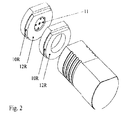
- Figure 2 is a back view of the inventive device 7, spacer element 4 and optical power sensor 1 shown in figure 1 and enables a better view on the projecting D- shaped portions 12 of adapter 7 and spacer ring 4. It further shows the location of the end 11R of optical fiber 11 in adapter 7, and the plane surface 12R of the projecting D- shaped portion 12 of the adapter 7 and the plane surface 12R of the projecting D- shaped portion 12 of the spacer element 4. Positions 10R depict the circular part of the projecting D- shaped portions 12 of adapter 7 and spacer ring 4.
Landscapes
- Physics & Mathematics (AREA)
- General Physics & Mathematics (AREA)
- Optics & Photonics (AREA)
- Optical Couplings Of Light Guides (AREA)
- Mechanical Coupling Of Light Guides (AREA)
Claims (10)
- Adapter (7) zum optischen Verbinden eines Endes einer optischen Faser (11, 11 R) mit einer optischen Komponente (1, 4), wobei der Adapter (7) beinhaltet:gekennzeichnet durcheine Führung (6), die zum Halten der optischen Faser (11, 11R) in einer vorgegebenen Position relativ zu einer optischen Achse der optischen Komponente (1, 4) angeordnet ist,einen Körper mit wenigstens einem Bereich (12) mit einem nach Einsetzen zur Achse der Faser nicht rotationssymmetrischen Querschnitt, der so geformt ist, daß er in ein passendes Gegenstück der optischen Komponente eingreift und die Führung hält,
magnetische Mittel (5), die an dem Körper angebracht und zum Verbinden des Adapters (7) mit der zugewandten optischen Komponente (1, 4) mittels entsprechender magnetischer Mittel (3) der optischen Komponente (1, 4) angeordnet sind. - System mit:einem Adapter (7) gemäß Anspruch 1 undeiner optischen Komponente (1, 4) mit:einem passenden Gegenstück zum Eingreifen in den Bereich (12) des Adapters (7) mit dem nach Einsetzen zur Achse der Faser nicht rotationssymmetrischen Querschnitt undmagnetischen Mitteln (3), die zum Verbinden des Adapters (7) mit der optischen Komponente (1, 4) mittels der entsprechenden magnetischen Mittel (5) des Adapters (7) angeordnet sind.
- System nach Anspruch 2, wobei die optische Komponente (1, 4) ein Gehäuse beinhaltet und wenigstens ein Teil des Gehäuses ein Gegenstück mit einem Querschnitt mit der gleichen Gegenstückform wie der nicht rotationssymmetrische Teil des Adapters (7) beinhaltet, was eine leichte Ausrichtung des Adapters relativ zu der optischen Komponente erlaubt.
- System nach Anspruch 2 oder 3, wobei:die optische Komponente ein Meßinstrument ist, wie ein optischer Leistungssensor (1) mit einer Photodiode (2), die auf der optischen Achse der optischen Faser (11, 11 R) angeordnet ist, oderdie optische Komponente ein Abstandshalterelement (4) ist, das außerdem einen zweiten Teil mit einem nicht rotationssymmetrischen Querschnitt an seiner entgegengesetzten Seite beinhaltet und der zweite Teil in ein Gegenstück einer weiteren optischen Komponente (1) eingreift.
- System nach Anspruch 2, wobei der Adapter (7) und/oder die Komponente (4) einen vorstehenden, D-förmigen Bereich (12) beinhalten, der in ein vertieftes, D-förmiges Gegenstück (8) von einer der optischen Komponenten (1, 4) eingreift.
- System nach Anspruch 5, wobei wenigstens der vorstehende, D-förmige Bereich (12) ein ferromagnetisches Material beinhaltet und in das Gegenstück (8) von einer der optischen Komponenten mittels einer magnetischen Kraft eingreift.
- System nach Anspruch 6, wobei das Gegenstück (8) einen oder mehrere Magnete (3, 5) beinhaltet, die den vorstehenden, D-förmigen Bereich (12) in dem Gegenstück (8) fixieren.
- System nach Anspruch 2, wobei der nicht rotationssymmetrische Bereich (12) und das Gegenstück (12) eine ebene Oberfläche (9) aufweisen.
- System nach Anspruch 8, wobei die ebene Oberfläche (9) einen oder mehrere Magnete (3, 5) beinhaltet, die unter der Oberfläche angeordnet sind.
- System nach Anspruch 9, wobei der Adapter (7) und/oder die optische Komponente (1, 4) wenigstens teilweise mit Kunststoff bedeckt sind/ist.
Priority Applications (4)
| Application Number | Priority Date | Filing Date | Title |
|---|---|---|---|
| DE69608894T DE69608894T2 (de) | 1996-08-19 | 1996-08-19 | Optischer Verbinder |
| EP96113242A EP0825463B1 (de) | 1996-08-19 | 1996-08-19 | Optischer Verbinder |
| US08/879,170 US6004045A (en) | 1996-08-19 | 1997-06-19 | Optical connector |
| JP21163697A JP4009349B2 (ja) | 1996-08-19 | 1997-08-06 | 光コネクタ |
Applications Claiming Priority (1)
| Application Number | Priority Date | Filing Date | Title |
|---|---|---|---|
| EP96113242A EP0825463B1 (de) | 1996-08-19 | 1996-08-19 | Optischer Verbinder |
Publications (2)
| Publication Number | Publication Date |
|---|---|
| EP0825463A1 EP0825463A1 (de) | 1998-02-25 |
| EP0825463B1 true EP0825463B1 (de) | 2000-06-14 |
Family
ID=8223118
Family Applications (1)
| Application Number | Title | Priority Date | Filing Date |
|---|---|---|---|
| EP96113242A Expired - Lifetime EP0825463B1 (de) | 1996-08-19 | 1996-08-19 | Optischer Verbinder |
Country Status (4)
| Country | Link |
|---|---|
| US (1) | US6004045A (de) |
| EP (1) | EP0825463B1 (de) |
| JP (1) | JP4009349B2 (de) |
| DE (1) | DE69608894T2 (de) |
Families Citing this family (7)
| Publication number | Priority date | Publication date | Assignee | Title |
|---|---|---|---|---|
| TW499582B (en) * | 2001-10-18 | 2002-08-21 | Browave Corp | Miniature optical add/drop multiplexer |
| US7108430B2 (en) * | 2003-02-21 | 2006-09-19 | Itt Manufacturing Enterprises, Inc. | Optic fiber terminus indexer |
| US6923578B2 (en) * | 2003-02-21 | 2005-08-02 | Itt Manufacturing Enterprises, Inc. | Optical terminus keying |
| DE102006053775A1 (de) * | 2006-11-15 | 2008-05-21 | Mtu Aero Engines Gmbh | Lichtwellenleiterkupplung |
| US9028153B2 (en) | 2011-10-27 | 2015-05-12 | Tyco Electronics Corporation | Optical fiber having core-to-core alignment |
| US9829655B2 (en) | 2012-01-12 | 2017-11-28 | Te Connectivity Corporation | Communication connector having an alignment mechanism |
| JP6106375B2 (ja) * | 2012-07-09 | 2017-03-29 | アトムメディカル株式会社 | 光線治療器 |
Family Cites Families (4)
| Publication number | Priority date | Publication date | Assignee | Title |
|---|---|---|---|---|
| US4812009A (en) * | 1987-06-30 | 1989-03-14 | American Telephone And Telegraph Company, At&T Bell Laboratories | Optical fiber connector |
| US4844582A (en) * | 1987-12-09 | 1989-07-04 | Giannini Gabriel M | Hybrid electro-optical connectors |
| EP0713111A1 (de) * | 1994-11-15 | 1996-05-22 | The Whitaker Corporation | Abgedichteter faseroptischer Mehrfachstecker |
| US5499311A (en) * | 1994-12-16 | 1996-03-12 | International Business Machines Corporation | Receptacle for connecting parallel fiber optic cables to a multichip module |
-
1996
- 1996-08-19 DE DE69608894T patent/DE69608894T2/de not_active Expired - Fee Related
- 1996-08-19 EP EP96113242A patent/EP0825463B1/de not_active Expired - Lifetime
-
1997
- 1997-06-19 US US08/879,170 patent/US6004045A/en not_active Expired - Fee Related
- 1997-08-06 JP JP21163697A patent/JP4009349B2/ja not_active Expired - Fee Related
Also Published As
| Publication number | Publication date |
|---|---|
| DE69608894T2 (de) | 2001-03-15 |
| DE69608894D1 (de) | 2000-07-20 |
| JP4009349B2 (ja) | 2007-11-14 |
| US6004045A (en) | 1999-12-21 |
| EP0825463A1 (de) | 1998-02-25 |
| JPH1082926A (ja) | 1998-03-31 |
Similar Documents
| Publication | Publication Date | Title |
|---|---|---|
| EP0330231B1 (de) | Steckbarer Verbinder | |
| EP0840152B1 (de) | Stecker mit faseroptischem Abschluss | |
| EP0205984B1 (de) | Endstück für optische Faser und Verfahren zur Herstellung | |
| US5666449A (en) | Optical waveguide device | |
| US9880360B2 (en) | Optical connector apparatus | |
| US6318902B1 (en) | Optical connector assembly using partial large diameter alignment features | |
| JP4727674B2 (ja) | 光ファイバ終端組立体 | |
| US8280205B2 (en) | Fiber optic connector and alignment mechanism for single lens multi-fiber connector | |
| US5867621A (en) | Adapter and guide pin assembly for coupling of fiber optic connectors | |
| US5940559A (en) | Fiber-optic test probe and connector adapter for testing fiber-optic connector harnesses | |
| US6805493B2 (en) | Optical connector assembly using partial large diameter alignment features | |
| US5577143A (en) | Multi channel connector | |
| BE900781A (nl) | Verbindingsinrichting voor optische vezels. | |
| US20100202730A1 (en) | Fiber optic jack and connector | |
| EP0825463B1 (de) | Optischer Verbinder | |
| US4799759A (en) | Fiber optic connector | |
| US5631990A (en) | Integrated optical module for coupling an optical fiber to an optical device | |
| US6234681B1 (en) | Apparatus and method for interconnecting optical fibers | |
| JPS62150306A (ja) | 分離可能な照準合せアツセンブル | |
| US5960137A (en) | Fiber-optic test probe and connector adapter for testing fiber-optic connector harnesses | |
| EP0674196A1 (de) | Faseroptischer Steckverbinder | |
| JPH08500195A (ja) | 光コネクタ | |
| CN218497196U (zh) | 用于光纤缆线的适配器组件 | |
| JPH10206282A (ja) | 光ファイバ心線の端末処理構造 | |
| WO2016162550A1 (en) | Method and apparatus for measuring guide pin hole angle of fiber optic ferrule |
Legal Events
| Date | Code | Title | Description |
|---|---|---|---|
| PUAI | Public reference made under article 153(3) epc to a published international application that has entered the european phase |
Free format text: ORIGINAL CODE: 0009012 |
|
| 17P | Request for examination filed |
Effective date: 19970210 |
|
| AK | Designated contracting states |
Kind code of ref document: A1 Designated state(s): DE FR GB |
|
| AKX | Designation fees paid |
Free format text: DE FR GB |
|
| RBV | Designated contracting states (corrected) |
Designated state(s): DE FR GB |
|
| 17Q | First examination report despatched |
Effective date: 19990128 |
|
| GRAG | Despatch of communication of intention to grant |
Free format text: ORIGINAL CODE: EPIDOS AGRA |
|
| GRAG | Despatch of communication of intention to grant |
Free format text: ORIGINAL CODE: EPIDOS AGRA |
|
| GRAH | Despatch of communication of intention to grant a patent |
Free format text: ORIGINAL CODE: EPIDOS IGRA |
|
| GRAH | Despatch of communication of intention to grant a patent |
Free format text: ORIGINAL CODE: EPIDOS IGRA |
|
| GRAA | (expected) grant |
Free format text: ORIGINAL CODE: 0009210 |
|
| AK | Designated contracting states |
Kind code of ref document: B1 Designated state(s): DE FR GB |
|
| REF | Corresponds to: |
Ref document number: 69608894 Country of ref document: DE Date of ref document: 20000720 |
|
| ET | Fr: translation filed | ||
| REG | Reference to a national code |
Ref country code: FR Ref legal event code: TP |
|
| REG | Reference to a national code |
Ref country code: GB Ref legal event code: 732E |
|
| RAP2 | Party data changed (patent owner data changed or rights of a patent transferred) |
Owner name: HEWLETT-PACKARD COMPANY, A DELAWARE CORPORATION |
|
| RAP2 | Party data changed (patent owner data changed or rights of a patent transferred) |
Owner name: AGILENT TECHNOLOGIES, INC. |
|
| PLBE | No opposition filed within time limit |
Free format text: ORIGINAL CODE: 0009261 |
|
| STAA | Information on the status of an ep patent application or granted ep patent |
Free format text: STATUS: NO OPPOSITION FILED WITHIN TIME LIMIT |
|
| 26N | No opposition filed | ||
| REG | Reference to a national code |
Ref country code: GB Ref legal event code: IF02 |
|
| PGFP | Annual fee paid to national office [announced via postgrant information from national office to epo] |
Ref country code: FR Payment date: 20060831 Year of fee payment: 11 |
|
| PGFP | Annual fee paid to national office [announced via postgrant information from national office to epo] |
Ref country code: GB Payment date: 20070830 Year of fee payment: 12 |
|
| PGFP | Annual fee paid to national office [announced via postgrant information from national office to epo] |
Ref country code: DE Payment date: 20071001 Year of fee payment: 12 |
|
| REG | Reference to a national code |
Ref country code: FR Ref legal event code: ST Effective date: 20080430 |
|
| PG25 | Lapsed in a contracting state [announced via postgrant information from national office to epo] |
Ref country code: FR Free format text: LAPSE BECAUSE OF NON-PAYMENT OF DUE FEES Effective date: 20070831 |
|
| GBPC | Gb: european patent ceased through non-payment of renewal fee |
Effective date: 20080819 |
|
| PG25 | Lapsed in a contracting state [announced via postgrant information from national office to epo] |
Ref country code: DE Free format text: LAPSE BECAUSE OF NON-PAYMENT OF DUE FEES Effective date: 20090303 |
|
| PG25 | Lapsed in a contracting state [announced via postgrant information from national office to epo] |
Ref country code: GB Free format text: LAPSE BECAUSE OF NON-PAYMENT OF DUE FEES Effective date: 20080819 |