EP0824231B2 - Manufacturing system - Google Patents
Manufacturing system Download PDFInfo
- Publication number
- EP0824231B2 EP0824231B2 EP97113438A EP97113438A EP0824231B2 EP 0824231 B2 EP0824231 B2 EP 0824231B2 EP 97113438 A EP97113438 A EP 97113438A EP 97113438 A EP97113438 A EP 97113438A EP 0824231 B2 EP0824231 B2 EP 0824231B2
- Authority
- EP
- European Patent Office
- Prior art keywords
- control unit
- accordance
- unit
- manufacturing plant
- functional
- Prior art date
- Legal status (The legal status is an assumption and is not a legal conclusion. Google has not performed a legal analysis and makes no representation as to the accuracy of the status listed.)
- Expired - Lifetime
Links
Images


Classifications
-
- G—PHYSICS
- G05—CONTROLLING; REGULATING
- G05B—CONTROL OR REGULATING SYSTEMS IN GENERAL; FUNCTIONAL ELEMENTS OF SUCH SYSTEMS; MONITORING OR TESTING ARRANGEMENTS FOR SUCH SYSTEMS OR ELEMENTS
- G05B19/00—Programme-control systems
- G05B19/02—Programme-control systems electric
- G05B19/04—Programme control other than numerical control, i.e. in sequence controllers or logic controllers
- G05B19/042—Programme control other than numerical control, i.e. in sequence controllers or logic controllers using digital processors
- G05B19/0421—Multiprocessor system
-
- G—PHYSICS
- G05—CONTROLLING; REGULATING
- G05B—CONTROL OR REGULATING SYSTEMS IN GENERAL; FUNCTIONAL ELEMENTS OF SUCH SYSTEMS; MONITORING OR TESTING ARRANGEMENTS FOR SUCH SYSTEMS OR ELEMENTS
- G05B2219/00—Program-control systems
- G05B2219/20—Pc systems
- G05B2219/25—Pc structure of the system
- G05B2219/25144—Between microcomputers, processors
-
- G—PHYSICS
- G05—CONTROLLING; REGULATING
- G05B—CONTROL OR REGULATING SYSTEMS IN GENERAL; FUNCTIONAL ELEMENTS OF SUCH SYSTEMS; MONITORING OR TESTING ARRANGEMENTS FOR SUCH SYSTEMS OR ELEMENTS
- G05B2219/00—Program-control systems
- G05B2219/20—Pc systems
- G05B2219/25—Pc structure of the system
- G05B2219/25232—DCS, distributed control system, decentralised control unit
-
- G—PHYSICS
- G05—CONTROLLING; REGULATING
- G05B—CONTROL OR REGULATING SYSTEMS IN GENERAL; FUNCTIONAL ELEMENTS OF SUCH SYSTEMS; MONITORING OR TESTING ARRANGEMENTS FOR SUCH SYSTEMS OR ELEMENTS
- G05B2219/00—Program-control systems
- G05B2219/20—Pc systems
- G05B2219/25—Pc structure of the system
- G05B2219/25234—Direct communication between two modules instead of normal network
Description
Die Erfindung betrifft eine Fertigungsanlage, umfassend eine Vielzahl von mindestens eine Funktion realisierenden, in der Fertigungsanlage zusammenwirkenden Funktionseinheiten, von denen jede mindestens einen Aktor und mindestens einen Sensor zur Funktionssteuerung und/oder Funktionsüberwachung aufweist.The invention relates to a manufacturing plant, comprising a plurality of at least one function implementing, cooperating in the manufacturing plant functional units, each of which has at least one actuator and at least one sensor for function control and / or function monitoring.
Bei derartigen Fertigungsanlagen wird bislang nach dem Konzept der sogenannten "Zentralen Intelligenz" gearbeitet, gemäß welchem jeder Funktionseinheit eine Einheit zugeordnet ist, die entweder Signale eines Sensors erfaßt und über einen sogenannten Feldbus zur zentralen Anlagensteuerung leitet oder Signale vom Zentralrechner erfaßt und gemäß diesen den Aktor ansteuert.In such manufacturing systems so far according to the concept of the so-called "Central Intelligence" worked, according to which each unit is assigned a unit that detects either signals from a sensor and passes via a so-called fieldbus to the central system control or detected signals from the central computer and according to these the actuator controls.
Dieses Konzept erfordert es, eine Vielzahl von Daten über den Feldbus auszutauschen, so daß allein hieraus eine erhebliche Störanfälligkeit resultiert.This concept makes it necessary to exchange a large number of data via the fieldbus, so that this alone results in a considerable susceptibility to interference.
Aus der
Der Erfindung liegt daher die Aufgabe zugrunde, eine Fertigungsanlage der gattungsgemäßen Art derart zu verbessern, daß diese wartungsfreundlich und weniger störanfällig ist.The invention is therefore an object of the invention to improve a manufacturing plant of the generic type such that it is easy to maintain and less prone to failure.
Diese Aufgabe wird durch eine Fertigungsanlage nach Anspruch 1 gelöst.This object is achieved by a manufacturing plant according to claim 1.
Der Vorteil der erfindungsgemäßen Lösung ist darin zu sehen, daß mit dieser nicht mehr jeder Funktionsschritt über den Feldbus im Zentralrechner bearbeitet wird, sondern die Steuereinheit die Möglichkeit eröffnet, die Funktionsschritte der Funktionseinheit eigenständig zu bearbeiten. Damit wird der Kommunikationsbedarf und somit auch die mit diesem verbundene Störanfälligkeit erheblich reduziert.The advantage of the solution according to the invention is the fact that with this no longer every functional step is processed via the fieldbus in the central computer, but the control unit opens up the possibility to edit the functional steps of the functional unit independently. This considerably reduces the need for communication and thus the susceptibility associated with it.
Der Modulaufbau der Steuereinheit der erfindungsgemäßen Fertigungsanlage hat den großen Vorteil, daß er einerseits sehr wartungsfreundlich ist und außerdem die Möglichkeit schafft, mehrere Leistungsmodule vorzusehen und somit mehrere Aktoren anzusteuern und außerdem mehrere Sensormodule vorzusehen, um mehrere Sensoren einsetzen zu können.The modular design of the control unit of the manufacturing plant according to the invention has the great advantage that on the one hand it is very easy to maintain and also creates the possibility to provide multiple power modules and thus to control multiple actuators and also provide multiple sensor modules to use multiple sensors can.
Rein prinzipiell wäre es bei dem erfindungsgemäßen Konzept nach wie vor möglich, bei besonderen, beispielsweise rechnerzeitaufwendigen Funktionen auf einen Zentralrechner über ein Bussystem zurückzugreifen. Dies hat jedoch den Nachteil, daß damit die Programmstruktur eine erhebliche Komplexität erhält.In principle, it would still be possible in the inventive concept to resort to a central computer via a bus system in the case of special functions, for example computer time-consuming functions. However, this has the disadvantage that it gives the program structure a considerable complexity.
Aus Gründen einer möglichst wenig aufwendigen Programmstruktur ist es daher besonders vorteilhaft, wenn jede Steuereinheit die gesamten vorgesehenen Funktionen mit dem Funktionssteuerprogramm eigenständig durchführt, das heißt sämtliche für die Funktionen erforderlichen Rechenoperationen selbst durchführt, so daß diesbezüglich jede Steuereinheit autark ist.For reasons of a less complicated program structure, it is therefore particularly advantageous if each control unit performs the entire intended functions independently with the function control program, that is, performs all necessary for the functions arithmetic operations themselves, so that in this regard each control unit is self-sufficient.
Der Vorteil dieser Lösung ist auch darin zu sehen, daß damit die Ausfallanfälligkeit erheblich reduziert wird, da die vorgesehenen Funktionen unabhängig von der Funktionsfähigkeit der Kommunikation der Steuereinheit mit anderen Einheiten durchführbar sind.The advantage of this solution is also to be seen in the fact that the susceptibility to failure is significantly reduced, since the functions provided are independent of the functionality of the communication of the control unit with other units feasible.
Im Extremfall wäre das erfindungsgemäße Konzept so realisierbar, daß das Funktionssteuerprogramm ohne Informationen über die anderen Steuereinheiten der anderen Funktionseinheiten arbeitet. Ein derartiges isoliertes Arbeiten ist jedoch bei komplexen Fertigungsanlagen nicht realisierbar.In an extreme case, the concept according to the invention would be so realizable that the function control program operates without information about the other control units of the other functional units. However, such isolated work is not feasible in complex manufacturing plants.
Aus diesem Grund ist es erforderlich, eine Kommunikation zwischen den einzelnen Funktionseinheiten vorzusehen. Dies wird erfindungsgemäß dadurch realisiert, daß die Steuereinheit einer Funktionseinheit direkt mit der Steuereinheit mindestens einer anderen der Funktionseinheiten kommuniziert. Das heißt, daß durch direkte Kommunikation der jeweiligen Steuereinheit mit der Steuereinheit mindestens einer anderen der Funktionseinheiten ein Informationsaustausch möglich ist, so daß trotz der eigenständigen Funktionsweise in jeder Steuereinheit Informationen von anderen Funktionseinheiten berücksichtigt werden können und folglich die Möglichkeit besteht, dieselben komplexen Steuerungsvorgänge mit einem dezentralen Steuerungssystem durchzuführen, wie im Fall des aus dem Stand der Technik bekannten Konzepts der "zentralen Intelligenz".For this reason, it is necessary to provide communication between the individual functional units. This is inventively realized in that the control unit of a functional unit communicates directly with the control unit of at least one other of the functional units. This means that an information exchange is possible by direct communication of the respective control unit with the control unit of at least one other of the functional units, so that despite the independent functioning in each control unit information from other functional units can be considered and consequently the possibility exists, the same complex control operations with a decentralized control system, as in the case of the prior art concept of "central intelligence".
Bei der erfindungsgemäßen Lösung ist beispielsweise vorgesehen, daß jede Steuereinheit alle für die Funktionen der Funktionseinheit notwendigen Funktionsparameter erfaßt und entsprechend diesen die Funktionseinheit steuert. Das heißt, daß die Steuereinheit als Eingangsgrößen lediglich Funktionsparameter erfaßt und damit in der Lage ist, selbständig sämtliche Steuerungsfunktionen abzuleiten. Diese Lösung hat den großen Vorteil, daß dadurch jede Steuereinheit als Eingabegrößen lediglich noch die Funktionsparameter benötigt, um in vollem Umfang die Funktionssteuerung durchführen zu können.In the solution according to the invention, for example, it is provided that each control unit detects all the functional parameters necessary for the functions of the functional unit and controls the functional unit in accordance with them. This means that the control unit only detects function parameters as input variables and is therefore able to independently derive all control functions. This solution has the great advantage that each control unit only requires the function parameters as input variables in order to be able to carry out the functional control in its entirety.
Aus diesem Grund ist vorgesehen, daß die Steuereinheit zumindest in einem Teil der Funktionsparameter durch Auswerten der Signale des mindestens einen Sensors umfaßt. Im einfachsten Fall einer erfindungsgemäßen Fertigungsanlage könnte es auch ausreichend sein, sämtliche Funktionsparameter durch Auswerten der Signale der dieser Steuereinheit zugeordneten Sensoren zu ermitteln.For this reason, it is provided that the control unit comprises, at least in part of the function parameters, by evaluating the signals of the at least one sensor. In the simplest case of a production plant according to the invention, it could also be sufficient to determine all the functional parameters by evaluating the signals of the sensors assigned to this control unit.
Wie bereits ausgeführt ist es jedoch bei komplexen Anlagen erforderlich, Informationen und damit Funktionsparameter von anderen Steuereinheiten zu erhalten, so daß in diesem Fall die Steuereinheit erfindungsgemäß einen Teil der Funktionsparameter durch Kommunikation mit mindestens einer der anderen Steuereinheiten der Fertigungsanlage erfaßt.However, as already stated, in complex systems it is necessary to obtain information and thus functional parameters from other control units, so that in this case the control unit detects part of the functional parameters by communication with at least one of the other control units of the production plant.
Im Falle einer vorgesehenen Kommunikation zwischen den einzelnen Steuereinheiten ist es besonders vorteilhaft, wenn alle Steuereinheiten der Fertigungsanlage an ein Bussystem angeschlossen sind und daher über das Bussystem miteinander kommunizieren können.In the case of a planned communication between the individual control units, it is particularly advantageous if all the control units of the manufacturing plant are connected to a bus system and therefore can communicate with each other via the bus system.
Ein derartiges Bussystem kann beispielsweise ein LON-Bus, ein INTERBUS oder ein PROFIBUS sein.Such a bus system may be, for example, a LON bus, an INTERBUS or a PROFIBUS.
Aus Gründen der Einfachheit der Kommunikation und der Flexibilität des Aufbaus der erfindungsgemäßen Fertigungsanlage ist vorzugsweise vorgesehen, daß jede Steuereinheit in der Lage ist, über das Bussystem Kommunikationssignale zu empfangen und auszusenden, so daß selbst dann, wenn im einen oder anderen Fall keinerlei Kommunikation prinzipiell nötig wäre, dies gegebenenfalls noch zu ändern.For the sake of simplicity of communication and the flexibility of the structure of the manufacturing plant according to the invention is preferably provided that each control unit is able to receive communication signals via the bus system and send out, so that even if in any case no communication in principle necessary would be to change this if necessary.
Prinzipiell wäre es ausreichend, die Steuereinheiten so auszubilden, daß in diesen das Funktionssteuerprogramm implementiert werden kann, beispielsweise durch Einsetzen eines entsprechenden Programmspeichers oder durch einen entsprechenden Programmieranschluß.In principle, it would be sufficient to design the control units in such a way that the function control program can be implemented in them, for example by inserting a corresponding program memory or by means of a corresponding programming connection.
Im Fall, daß jede Steuereinheit ohnehin über ein Bussystem kommuniziert, ist es besonders vorteilhaft, wenn jede Steuereinheit über das Bussystem programmierbar ist, da das Bussystem eine besonders einfache und vorteilhafte Möglichkeit bietet, jede Steuereinheit zu erreichen und somit über eine mit dem Bussystem verbundene Programmierstation jede Steuereinheit zu programmieren, beispielsweise dadurch, daß von der Programmierstation ein mittels dieser erstelltes Funktionssteuerprogramm über das Bussystem in die jeweilige Steuereinheit geladen wird.In the event that each control unit communicates anyway via a bus system, it is particularly advantageous if each control unit is programmable via the bus system, since the bus system offers a particularly simple and advantageous possibility of reaching each control unit and thus via a programming station connected to the bus system to program each control unit, for example, by the fact that is loaded from the programming station created by this function control program via the bus system in the respective control unit.
Ferner sieht eine vorteilhafte Variante des erfindungsgemäßen Konzepts vor, daß die Arbeitsweise jeder Steuereinheit über das Bussystem überprüfbar ist, so daß über das Bussystem die Möglichkeit besteht, sowohl Störungen der Hardware als auch der Software zu erkennen.Furthermore, an advantageous variant of the inventive concept provides that the operation of each control unit via the bus system is verifiable, so that via the bus system has the ability to detect both hardware and software malfunctions.
Dies läßt sich im einfachsten Fall dadurch realisieren, daß jede Steuereinheit über das Bussystem Fehlermeldungen abgibt, beispielsweise wenn bei laufendem Funktionssteuerprogramm ein Programmfehler oder ein Hardwarefehler auftritt.In the simplest case, this can be achieved by each control unit issuing error messages via the bus system, for example if a program error or a hardware error occurs while the function control program is running.
Im Zusammenhang mit der bisherigen Beschreibung der erfindungsgemäßen Fertigungsanlage wurde nicht näher spezifiziert, wie die Steuereinheit lokal angeordnet ist.In connection with the previous description of the manufacturing plant according to the invention was not specified in more detail how the control unit is located locally.
Beispielsweise wäre es möglich, alle Steuereinheiten - so wie bisher der Fall - in einer Schaltschrankanlage zusammenzufassen, welche lokal völlig separat von der Fertigungsanlage angeordnet ist.For example, it would be possible to combine all the control units - as was previously the case - in a control cabinet system, which is located locally completely separate from the manufacturing plant.
Besonders vorteilhaft ist es jedoch, wenn jeder Funktionseinheit die Steuereinheit lokal zugeordnet ist, so daß dadurch das Erfordernis entfällt, eine Vielzahl von Leitungen von der Schaltschrankanlage zu den einzelnen Funktionseinheiten zu führen, um deren Aktoren und Sensoren mit der Schaltschrankanlage zu verbinden.It is particularly advantageous, however, if each functional unit, the control unit is assigned locally, thereby eliminating the need to run a variety of lines from the control panel system to the individual functional units to connect their actuators and sensors with the control cabinet system.
Noch vorteilhafter ist ein Ausführungsbeispiel, bei welchem der mindestens eine Aktor und der mindestens eine Sensor jeder Steuereinheit mit der Funktionseinheit direkt verdrahtet sind, so daß die Möglichkeit besteht, die Funktionseinheit zusammen mit der Steuereinheit zu fertigen und auch bei der Fertigung eine direkte Verdrahtung der beiden miteinander vorzunehmen.Even more advantageous is an embodiment in which the at least one actuator and the at least one sensor of each control unit are directly wired to the functional unit, so that there is the possibility to manufacture the functional unit together with the control unit and also in the production of a direct wiring of the two to each other.
Nach Aufbau der Fertigungsanlage ist es somit lediglich noch erforderlich, die Steuereinheit mit den jeweiligen Zuleitungen zu verbinden.After building the production system, it is therefore only necessary to connect the control unit with the respective supply lines.
Eine besonders vorteilhafte Lösung sieht dabei vor, daß jede Steuereinheit an der jeweiligen Funktionseinheit unmittelbar angeordnet, das heißt mit deren Gestell oder Rahmen verbunden ist und somit bei der Fertigung der Funktionseinheit unmittelbar die Steuereinheit montiert und verdrahtet werden kann.A particularly advantageous solution provides that each control unit is arranged directly on the respective functional unit, that is to say connected with its frame or frame, and thus the control unit can be directly mounted and wired during production of the functional unit.
Im Fall einer lokalen Zuordnung der Steuereinheit zur Funktionseinheit ist vorteilhafterweise vorgesehen, daß das Bussystem zu jeder lokal der jeweiligen Funktionseinheit zugeordneten Steuereinheit geführt ist.In the case of a local assignment of the control unit to the functional unit is advantageously provided that the bus system is routed to each locally the respective functional unit associated control unit.
Ein besonders vorteilhaftes Ausführungsbeispiel sieht vor, daß jede Steuereinheit einen zentralrechnerunabhängig und funktionsprogrammgesteuert arbeitenden intelligenten Prozessormodul aufweist.A particularly advantageous embodiment provides that each control unit has a central processor-independent and function program-controlled operating intelligent processor module.
Um eine Verbindung zwischen dem Bussystem und dem Prozessormodul herzustellen, ist vorzugsweise vorgesehen, daß der Prozessormodul eine Sende- und Empfangseinheit aufweist, welche eine Verbindung zwischen einer Prozessoreinheit des Prozessormoduls und dem Bussystem herstellt.In order to establish a connection between the bus system and the processor module, it is preferably provided that the processor module has a transmitting and receiving unit which establishes a connection between a processor unit of the processor module and the bus system.
Um - insbesondere bei einer lokal der Funktionseinheit zugeordneten Steuereinheit - für Wartungspersonal Informationen unmittelbar zur Verfügung zu stellen, ist vorgesehen, daß jede Steuereinheit einen eine Funktionsanzeige betreibenden Anzeigemodul aufweist.In order to provide information to maintenance personnel, especially in the case of a control unit locally assigned to the functional unit, it is provided that each control unit has a display module which operates a function display.
Mit diesem Anzeigemodul ist es beispielsweise möglich, alle Arten von Betriebszuständen anzuzeigen. Besonders vorteilhaft ist es jedoch, wenn dieser Anzeigemodul dazu eingesetzt wird, über die Funktionsanzeige eine Fehleranzeige zu machen.For example, with this display module it is possible to display all types of operating conditions. However, it is particularly advantageous if this display module is used to over the function display to make an error message.
Um ferner, insbesondere im Notfallbetrieb, direkt auf die jeweilige Steuereinheit zugreifen und diese im Notfallbetrieb betreiben zu können, ist vorgesehen, daß jede Steuereinheit einen eine Eingabeeinheit betreibenden Ein-/Ausgabemodul umfaßt. Damit besteht beispielsweise die Möglichkeit, über einen manuell betätigbares Terminal einzusetzen, um die Steuereinheit funktionsfähig zu halten. Insbesondere in all den Fällen, in welchen die jeweilige Steuereinheit mit anderen Steuereinheiten kommuniziert, um über diese für das eigene Funtionssteuerprogramm erforderliche Funktionsparameter zu erfassen, ist es besonders vorteilhaft, wenn mit der Eingabeeinheit im Normalbetrieb von anderen Steuereinheiten für die jeweilige Steuereinheit erzeugte Kommunikationssignale, beispielsweise Funktionsparameter enthaltende Kommunikationssignale, generierbar sind. Damit ist die Möglichkeit geschaffen, mit der erfindungsgemäßen Steuereinheit - beispielsweise obwohl das Bussystem ausgefallen ist - die entsprechende Funktionseinheit betreiben zu können.Furthermore, in order, in particular in emergency mode, to be able to access the respective control unit directly and operate it in emergency mode, it is provided that each control unit comprises an input / output module operating an input unit. Thus, for example, it is possible to use a manually operable terminal to keep the control unit functional. In particular, in all the cases in which the respective control unit communicates with other control units in order to detect these functional parameters required for the own function control program, it is particularly advantageous if communication signals generated by the other control units for the respective control unit with the input unit in normal operation, for example Functional parameters containing communication signals can be generated. This creates the opportunity to operate the corresponding functional unit with the control unit according to the invention - for example, although the bus system has failed.
Ferner ist es ebenfalls vorgesehen, daß über die Eingabeeinheit ein Störfallbetriebsmodus der Steuereinheit aktivierbar ist, in welchem der Leistungsmodul derselben direkt ansteuerbar ist, das heißt, daß in diesem Fall keine Steuerung mehr über das Funktionssteuerprogramm mehr erfolgt, sondern eine direkte Ansteuerung des Leistungsmoduls über die Eingabeeinheit.Furthermore, it is also envisaged that via the input unit an accident mode of operation of the control unit can be activated, in which the power module of the same is directly controlled, that is, in this case, no more control via the function control program, but a direct control of the power module on the input unit.
Eine derartige Steuerung eines Leistungsmoduls direkt über die Eingabeeinheit ist dann sinnvoll möglich, wenn erkennbar ist, welche Signale oder Parameter von den Sensoren erfaßt werden.Such a control of a power module directly via the input unit is meaningfully possible if it is apparent which signals or parameters are detected by the sensors.
Aus diesem Grund sieht eine besonders vorteilhafte Lösung vor, daß die vom Sensor erfaßten Funktionsparameter von der Eingabeeinheit anzeigbar sind.For this reason, a particularly advantageous solution provides that the function parameters detected by the sensor can be displayed by the input unit.
Im Zusammenhang mit der bisherigen Beschreibung der erfindungsgemäßen Fertigungsanlage wurde nicht im einzelnen darauf eingegangen, wie die Fertigungsanlage in die einzelnen Funktionseinheiten unterteilt ist.In connection with the previous description of the manufacturing plant according to the invention was not discussed in detail how the manufacturing plant is divided into the individual functional units.
So sieht ein besonders vorteilhaftes Ausführungsbeispiel vor, daß jede Funktionseinheit einen eigenen Funktionsabschnitt der Fertigungsanlage bildet und somit die Funktionseinheiten entsprechend den einzelnen Teilfunktionen der Fertigungsanlage konzipiert sind.Thus, a particularly advantageous embodiment provides that each functional unit forms its own functional section of the manufacturing plant and thus the functional units are designed according to the individual sub-functions of the manufacturing plant.
Vorzugsweise ist die erfindungsgemäße Fertigungsanlage so aufgebaut, daß diese eine Eingangseinheit und eine Ausgangseinheit für zu bearbeitendes Gut aufweist und daß das Gut die zwischen der Eingangseinheit und der Ausgangseinheit angeordneten Funktionseinheiten durchläuft.Preferably, the manufacturing plant according to the invention is constructed so that it has an input unit and an output unit for material to be processed and that the estate passes through the arranged between the input unit and the output unit functional units.
Auch jede Funktionseinheit kann zweckmäßigerweise so ausgebildet sein, daß sie einen Einlaß zum Übernehmen des Guts und einen Auslaß zum Übergeben des Guts aufweist. In diesem Fall läßt sich der Durchlauf des Guts durch die jeweilige Funktionseinheit besonders einfach mit Sensoren erfassen.Also, each functional unit may conveniently be designed so that it has an inlet for taking over the Guts and an outlet for transferring the Guts. In this case, the passage of the material through the respective functional unit can be detected particularly easily with sensors.
Eine besonders günstige funktionelle Struktur der erfindungsgemäßen Fertigungsanlage sieht vor, daß jede zwischen der Eingangseinheit und der Ausgangseinheit angeordnete Funktionseinheit das Gut von der vorangehenden Funktionseinheit übernimmt und nach Realisierung der eigenen Funktion an die nachfolgende Funktionseinheit abgibt.A particularly favorable functional structure of the production plant according to the invention provides that each functional unit arranged between the input unit and the output unit takes over the good from the preceding functional unit and, after realization of its own function, delivers it to the following functional unit.
Darüber hinaus wird die eingangs genannte Aufgabe auch durch ein Verfahren zum Betreiben einer Fertigungsanlage nach Anspruch 19 gelöst.In addition, the object mentioned above is also achieved by a method for operating a production plant according to claim 19.
Der Vorteil der erfindungsgemäßen Lösung ist ebenfalls darin zu sehen, daß damit die Notwendigkeit einer Kommunikation erheblich verringert wird und somit auch die Störanfälligkeit einer derartigen Fertigungsanlage erheblich reduziert wird.The advantage of the solution according to the invention is also to be seen in the fact that thus the need for communication is significantly reduced and thus the susceptibility of such a production system is significantly reduced.
Besonders zweckmäßig ist es dabei, wenn von jeder Steuereinheit die gesamten vorgesehenen Funktionen eigenständig gesteuert werden.It is particularly expedient if the entire intended functions are independently controlled by each control unit.
Ein besonders zweckmäßiges erfindungsgemäßes Verfahren sieht vor, daß die jeweilige Steuereinheit direkt mit der Steuereinheit mindestens einer anderen der Funktionseinheiten kommuniziert, für den Fall, daß es erforderlich ist, Informationen über Funktionen der anderen Steuereinheiten zu erhalten und verarbeiten zu können, was insbesondere für das Betreiben komplexer Fertigungsanlagen erforderlich ist.A particularly expedient method according to the invention provides that the respective control unit communicates directly with the control unit of at least one other of the functional units, in the event that it is necessary to be able to obtain and process information about functions of the other control units, in particular for the operation complex manufacturing equipment is required.
Eine besonders günstige Variante des erfindungsgemäßen Verfahrens sieht vor, daß von jeder Steuereinheit alle für die Funktion der Funktionseinheit notwendigen Funktionsparameter erfaßt werden und entsprechend diesen die Funktionseinheit gesteuert wird. Damit ist es für jede Steuereinheit lediglich erforderlich, noch Funktionsparameter zu erfassen und die Steuereinheit ist in der Lage, alle übrigen für die Steuerung der Funktionen erforderlichen Rechenoperationen selbst durchzuführen.A particularly favorable variant of the method according to the invention provides that all functional parameters necessary for the function of the functional unit are detected by each control unit and the functional unit is controlled in accordance therewith. Thus, it is only necessary for each control unit to detect functional parameters and the control unit is able to carry out all other arithmetic operations required for the control of the functions itself.
Die Funktionsparameter werden zumindest zu einem Teil durch Auswerten der Signale des mindestens einen Sensors der Steuereinheit erfaßt, so daß hierzu keinerlei Kommunikation erforderlich ist.The function parameters are detected at least in part by evaluating the signals of the at least one sensor of the control unit, so that no communication is required for this purpose.
Wie bereits erwähnt ist es jedoch bei komplexen Fertigungsanlagen erforderlich, Informationen, insbesondere Funktionsparametern von anderen Steuereinheiten zu erhalten. Aus diesem Grund ist vorgesehen, daß von der Steuereinheit ein Teil der Funktionsparameter durch direkte Kommunikation mit mindestens einer anderen der Steuereinheiten der Fertigungsanlage erfaßt wird.As already mentioned, however, complex production equipment requires information, in particular functional parameters, to be obtained from other control units. For this reason, it is provided that a part of the functional parameters is detected by the control unit by direct communication with at least one other of the control units of the manufacturing plant.
Die Kommunikation zwischen den Steuereinheiten erfolgt vorzugsweise so, daß von allen Steuereinheiten Informationen an ein Bussystem abgegeben oder von einem Bussystem empfangen werden.The communication between the control units preferably takes place in such a way that information from all control units is output to a bus system or received by a bus system.
Ein besonders einfacher Zugriff ist auf die einzelnen Steuereinheiten dann möglich, wenn jede Steuereinheit über das Bussystem programmiert werden kann, so daß das Bussystem nicht nur zur Übermittlung von Kommunikationen, sondern auch zur Übermittlung von Programminformationen für die einzelnen Steuereinheiten vorteilhafterweise eingesetzt werden kann.A particularly simple access to the individual control units is possible if each control unit can be programmed via the bus system, so that the bus system not only for transmission Of communications, but also for the transmission of program information for the individual control units can be advantageously used.
Darüber hinaus läßt sich das Bussystem weiterhin noch vorteilhaft einsetzen, wenn die Arbeitsweise jeder Steuereinheit über das Bussystem überprüft werden kann.In addition, the bus system can still be used advantageously if the operation of each control unit can be checked via the bus system.
Dies läßt sich im einfachsten Fall dadurch realisieren, daß von jeder Steuereinheit über das Bussystem Fehlermeldungen abgegeben werden.This can be realized in the simplest case, that error messages are issued by each control unit via the bus system.
Weitere Merkmale und Vorteile der Erfindung sind Gegenstand der nachfolgenden Beschreibung sowie der zeichnerischen Darstellung einiger Ausführungsbeispiele.Further features and advantages of the invention are the subject of the following description and the drawings of some embodiments.
In der Zeichnung zeigen:
- Fig. 1
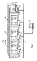
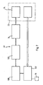
- eine schematische ausschnittsweise Darstellung eines ersten Ausführungsbeispiels einer erfindungsgemäßen Fertigungsanlage;
- Fig. 2
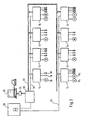
- eine schematische Darstellung ähnlich
Fig. 1 eines zweiten Ausführungsbeispiels einer erfindungsgemäßen Fertigungsanlage; - Fig. 3
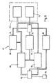
- eine schematische Darstellung der Verbindung zwischen den Steuereinheiten untereinander und mit den notwendigen Versorgungen bei einem erfindungsgemäßen dezentralen Steuerungssystem;
- Fig. 4
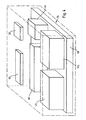
- eine schematische Darstellung einzelner Module einer erfindungsgemäßen Steuereinheit;
- Fig. 5
- eine schematische Darstellung der wichtigsten Komponenten des Basismoduls;
- Fig. 6
- eine schematische Darstellung der wichtigsten Komponenten des Leistungsmoduls;
- Fig. 7
- eine schematische Darstellung der wichtigsten Komponenten des Sensormoduls und
- Fig. 8
- eine schematische Darstellung der wichtigsten Komponenten des Prozessormoduls.
- Fig. 1
- a schematic partial view of a first embodiment of a manufacturing plant according to the invention;
- Fig. 2
- a schematic representation similar
Fig. 1 a second embodiment of a manufacturing plant according to the invention; - Fig. 3
- a schematic representation of the connection between the control units with each other and with the necessary supplies in a decentralized control system according to the invention;
- Fig. 4
- a schematic representation of individual modules of a control unit according to the invention;
- Fig. 5
- a schematic representation of the main components of the base module;
- Fig. 6
- a schematic representation of the main components of the power module;
- Fig. 7
- a schematic representation of the main components of the sensor module and
- Fig. 8
- a schematic representation of the main components of the processor module.
Ein Ausführungsbeispiel einer erfindungsgemäßen Fertigungsanlage, exemplarisch dargestellt in
An jeder dieser Funktionseinheiten 10 ist unmittelbar an einem Gestell 11 derselben eine Steuereinheit 14 angeordnet, welche dazu dient, einerseits einen als Aktor 16 dienenden und in diesem Fall die Rollen antreibenden Aktor M anzusteuern, wobei die Ansteuerung des Aktors 16 über Signale von Sensoren 18 erfolgt, welche beispielsweise als Funktionsparameter die Position des Guts 12 längs der Fertigungsanlage ermitteln, so daß ein Transport des Gutes 12 längs der einzelnen Funktionseinheiten 10 entsprechend der tatsächlichen Position des Guts 12 und der vom Fertigungsablauf her geforderten Position des Guts 12 erfolgen kann.At each of these
Jede der Steuereinheiten 14 ist mit einem Leistungsversorgungsnetz 20 direkt verbunden, welches die elektrische Leistung für den Betrieb der Aktoren 16 zur Verfügung stellt.Each of the
Darüber hinaus ist jede Funktionseinheit 10 mit einem Bussystem 22 verbunden, welches eine Kommunikation zwischen den einzelnen Steuereinheiten 14 erlaubt.In addition, each
Mit dem Bussystem 22 ist ferner noch eine Zentralstation 24 verbunden, deren Funktion nachfolgend noch im einzelnen erläutert wird.Furthermore, a
Bei einem zweiten Ausführungsbeispiel einer erfindungsgemäßen Fertigungsanlage, dargestellt in
Um das Werkstück 12 durch die einzelnen Trocknereinheiten 10T zu transportieren, ist zusätzlich jeder Trocknereinheit 10T noch eine Fördereinheit 10F als Funktionseinheit zugeordnet, die ebenfalls über eine dieser jeweils lokal zugeordnete Steuereinheit 14F ansteuerbar ist, und zwar beispielsweise in der gleichen Weise, wie grundsätzlich im Zusammenhang mit dem ersten Ausführungsbeispiel gemäß
Das heißt, daß bei dem zweiten Ausführungsbeispiel in jedem Abschnitt der Fertigungsanlage als selbständige Funktionseinheiten 10 nebeneinander sowohl eine Trocknereinheit 10T als auch eine Fördereinheit 10F angeordnet sind, wobei jede mit einer erfindungsgemäßen Steuereinheit 14T bzw. 14F ausgerüstet ist und alle miteinander über dasselbe Bussystem 22 kommunizieren und außerdem über dasselbe Leistungsversorgungsnetz 20 versorgt sind.That is, in the second embodiment, in each section of the manufacturing facility, as stand-alone
Das erfindungsgemäße Konzept der Verbindung aller selbständigen Steuereinheiten 14, beispielsweise über ein LON Bussystem 22 ist nochmals in
Am LON Bussystems 22 ist beispielsweise eine Mensch-Maschine-Schnittstelle 30 vorgesehen, welcher über das LON Bussystem 22 mit den einzelnen Steuereinheiten 14 kommuniziert.On
Ferner ist auf das LON Bussystem 22 noch ein externer Zugriff, beispielsweise über einen externen Computer 32 mittels eines Adapters 34 möglich, wobei beispielsweise über diesen externen Computer 32 eine Kommunikation mit den einzelnen Steuereinheiten 14 möglich ist.Furthermore, external access to the
Wie bereits beschrieben, ist jeder dieser Steuereinheiten 14 einer oder mehrere Aktoren 16 und einer oder mehrere Sensoren 18 zugeordnet, um die entsprechende Funktionseinheit 10 anzusteuern.As already described, each of these
Ferner ist jede Steuereinheit mit dem Leistungsversorgungsnetz 20 verbunden, welches seinerseits von einer zentralen Versorgungsstation 36 gespeist ist.Furthermore, each control unit is connected to the
Wie in
Ferner ist mit dem Basismodul 40 ein Prozessormodul 44 und eine variable Zahl von Sensormodulen 46, entsprechend der Zahl der Sensoren verbunden.Furthermore, a
Eine Anzeige der Funktion und Arbeitsweise der Steuereinheit 14 erfolgt über einen Anzeigemodul 50 und ferner ist über eine Eingabeeinheit 52 - beispielsweise ein Handterminalein BUS-externer Zugriff auf die Steuereinheit 14 möglich.An indication of the function and operation of the
Wie in
Ferner ist das Basismodul 40 mit einem Anschluß 58 für das Bussystem 22 versehen, welcher mit einem Anschluß 60 für den Prozessormodul 44 verbunden ist. Der Prozessormodul 44 ist außerdem noch mit einer Niederspannungsversorgung 62 verbunden, welche von der Spannungsaufbereitungseinheit 56 gespeist ist.Furthermore, the
Die Niederspannungsversorgung 62 versorgt beispielsweise außerdem noch einen Buscontroller 64 eines internen Bussystems 74 der Steuereinheit 14, einen Anschluß 66 des Sensormoduls 46, einen Anschluß 68 des Anzeigemoduls 50, einen Anschluß 70 der Eingabeeinheit 52 und Anschlüsse 72 für die Leistungsmodule 42.The low-
Ferner sind der Anschluß 60 des Prozessormoduls 44, der Anschluß 66 des Ein/Ausgabemoduls 48, der Anschluß 68 des Anzeigemoduls 50, der Anschluß 70 für die Eingabeeinheit 52 und die Anschlüsse 72 für die Leistungsmodule 42 mit dem Prozessormodul 44, beispielsweise über das interne Bussystem 74, verbunden, welches der internen Kommunikation der einzelnen Module der jeweiligen Steuereinheit 14 dient.Further, the
Jeder der Leistungsmodule 42 umfaßt seinerseits, wie in
Die Leistungselektronik 80 ist ferner ihrerseits mit einem Anschluß 82 für den Aktor 16, beispielsweise einen Motor M, verbunden, in welchem diesem die erforderliche Energie zugeführt wird.The
Die Leistungselektronik 80 wird angesteuert über eine Steuerschaltung 84, welche mit dem Prozessormodul 44, beispielsweise mittels des internen Bussystems 74, verbunden ist, wobei die Verbindung mit dem internen Bussystem 74 ebenfalls über den Anschluß 72 erfolgt. Die Steuerschaltung 84 steuert jedoch nicht nur die Leistungselektronik 80, sondern auch eine Versorgung 86 für ein dem Aktor 16 zugeordnetes Bremsrelais, wobei die Ansteuerung dieses Bremsrelais über den Motoranschluß 82 erfolgt.The
Zusätzlich ist in jedem Leistungsmodul 42 eine Phasenüberwachung 88 vorgesehen, welche zur Überwachung der der Leistungselektronik 80 zugeführten elektrischen Energie dient. Die Phasenüberwachung 88 ist ebenfalls mit dem Prozessormodul 44, beispielsweise mittels des internen Bussystems 74, verbunden und übermittelt über dieses Phaseninformation beispielsweise der Steuerschaltung 84.In addition, a
Ferner ist mit dem Motoranschluß 82 noch eine Motortemperaturüberwachung 90 verbunden, welche mit dem Prozessormodul 44, beispielsweise über das interne Bussystem 74, mit der Steuerschaltung 84 ebenfalls Information über die Motortemperatur austauscht.Furthermore, a motor temperature monitor 90 is connected to the
Jeder Sensormodul 46 umfaßt, wie in
Ferner ist über den Anschluß 72 eine direkte Versorgung des Sensoranschlusses 102 mit vom Basismodul 40 zur Verfügung gestellter Niederspannung vorgesehen.Furthermore, a direct supply of the
Wie in
Die Prozessoreinheit 110 kommuniziert dabei mit einer Sende-/Empfangseinheit 116 für das Bussystem 22, welche über den Anschluß 60 mit dem Bussystem 22 verbunden ist und über welche somit die Kommunikation mit dem Bussystem 22 erfolgt.The
In dem Programmspeicher 114 ist ein Funktionssteuerprogramm niedergelegt, welches es erlaubt, sämtliche Funktionen der Funktionseinheit 10 zu steuern.In the
Claims (27)
- A manufacturing plant comprising a plurality of functional units (10) which implement at least one function and which co-operate with one another in the manufacturing plant and each of which comprises at least one actuator (16) and at least one sensor (18) for function control and/or function monitoring, characterised in that each functional unit (10) comprises at least one intelligent control unit (14) which drives the functional unit (10) independently of a central computer in accordance with an individual function control programme stored in a programme store (114) and which controls the at least one actuator (16) and/or evaluates the signals from the at least one sensor (18) in accord with the function control programme,
whereby each control unit (14) comprises
a power module (42) controlling the at least one actuator (16), whereby said module (42) is provided with a connector terminal (82), for supplying the requisite energy to the actuator (16), and with a phase monitoring means (88),
a sensor module (46) for driving the at least one sensor (18) and receiving the signals therefrom, whereby said module (46) is provided with a sensor connector terminal (102) for supplying the sensor (18) with a low tension voltage,
a base module (40) which is provided with a connector terminal (54) for a power supply network (20) which runs to the control unit (14), with a connector terminal (72) for the power module (42) via which said power module (42) is supplied with electrical power, and with a connector terminal (72) for the sensor module (46) through which the sensor connector terminal (102) is supplied with low tension voltage, and
an input/output module (48) driving an input unit (52), wherein a fault operation mode of the control unit, in which the power module (42) is directly controllable, can be activated by the input unit (52). - A manufacturing plant in accordance with Claim 1, characterised in that each control unit (14) carries out all of the envisaged functions independently using the function control programme.
- A manufacturing plant in accordance with Claim 1 or 2, characterised in that the control unit (14) for one functional unit (10) communicates directly with the control unit (14) of at least one of the other functional units (10).
- A manufacturing plant in accordance with any of the preceding Claims, characterised in that each control unit (14) acquires all of the functional parameters required for the functioning of the functional unit (10) and controls the functional unit (10) in accordance therewith.
- A manufacturing plant in accordance with any of the preceding Claims, characterised in that all of the control units (14) in the manufacturing plant are connected to a bus system (22).
- A manufacturing plant in accordance with Claim 5, characterised in that each control unit (14) is capable of receiving and transmitting communications signals over the bus system (22).
- A manufacturing plant in accordance with Claim 6, characterised in that each control unit (14) is programmable over the bus system (22).
- A manufacturing plant in accordance with Claim 6 or 7, characterised in that the operation of each control unit (14) is adapted to be checked over the bus system (22).
- A manufacturing plant in accordance with any of the Claims 6 to 8, characterised in that each control unit (14) transmits error messages over the bus system (22).
- A manufacturing plant in accordance with any of the preceding Claims, characterised in that the control unit (14) is associated locally with each functional unit (10).
- A manufacturing plant in accordance with Claim 10, characterised in that the at least one actuator (16) and the at least one sensor (18) in each control unit (14) are wired directly to the functional unit (10).
- A manufacturing plant in accordance with Claim 10 or 11, characterised in that each control unit (14) is arranged directly on the respective functional unit (10).
- A manufacturing plant in accordance with any of the Claims 10 to 12, characterised in that the bus system (22) runs to each control unit associated locally with the functional unit (10).
- A manufacturing plant in accordance with any of the preceding Claims, characterised in that each control unit (14) comprises an intelligent processor module (44) which operates independently of a central computer under the control of the function programme, whereby the processor module (44) comprises a transmitting and receiving unit (116) which produces a connection between a processor unit (110) in the processor module (44) and a bus system (22).
- A manufacturing plant in accordance with any of the Claims 1 to 14, characterised in that each control unit (14) comprises an indicator module (50) driving a function display means.
- A manufacturing plant in accordance with any of the claims 1 to 15, characterised in that communications signals produced in normal operation by other control units (14) for the respective control unit (14) can be generated by the input unit (52).
- A manufacturing plant in accordance with any of the Claims 1 to 16, characterised in that the functional parameters acquired by the sensor (18) are displayable by the input unit (52).
- A manufacturing plant in accordance with any of the preceding Claims, characterised in that each functional unit (10) forms an individual functional section of the manufacturing plant.
- A method of operating a manufacturing plant comprising a plurality of functional units (10) which implement at least one function and which co-operate with one another in the manufacturing plant and each of which comprises at least one actuator (16) and at least one sensor (18) for function control and/or function monitoring, characterised in that each functional unit (10) is driven by a control unit (14) independently of a central computer in accordance with an individual function control programme stored in a programme store (114), whereby the actuator (16) is controlled and/or the signals from the sensor (18) are evaluated in accord with the function control programme,
in that the at least one actuator (16) is controlled by a power module (42) of the control unit (14), a phase monitoring means (88) being provided in the power module, and the requisite energy for the actuator (16) is supplied via a connector terminal (82) of said power module (42),
in that the at least one sensor (18) is driven by a sensor module (46) of the control unit (14), and the sensor (18) is supplied with a low tension voltage via a sensor connector terminal (102) of said sensor module (46),
in that a base module (40) of the control unit (14) is connected to a power supply network (20) which runs to the control unit (14), the power module (42) is supplied with electrical power via a connector terminal (72) of the base module (40) and the sensor module (46) is supplied with low tension voltage via a connector terminal (72) of the base module (40), and
in that an input/output module (48) of the control unit (14) drives an input unit (52), wherein, in the case of a fault, there is activated via the input unit (52) a fault operation mode of the control unit (14), in which the power module (42) is directly controlled. - A method in accordance with Claim 19, characterised in that all of the envisaged functions are controlled independently in each control unit (14).
- A method in accordance with Claim 19 or 20, characterised in that the respective control unit (14) communicates directly with the control unit (14) of at least one of the other functional units (10).
- A method in accordance with any of the Claims 19 to 21, characterised in that each of the functional parameters required for the functioning of the functional unit are acquired by each control unit and the functional unit is controlled in accordance therewith.
- A method in accordance with Claim 22, characterised in that a portion of the functional parameters is acquired by the control unit by means of direct communication with at least one of the other control units in the manufacturing plant.
- A method in accordance with any of the Claims 19 to 23, characterised in that information is transmitted to a bus system or is received from a bus system by all of the control units.
- A method in accordance with Claim 24, characterised in that each control unit can be programmed over the bus system.
- A method in accordance with Claim 24 or 25, characterised in that the operation of each control unit can be checked over the bus system.
- A method in accordance with Claim 26, characterised in that error messages are transmitted over the bus system by each control unit.
Priority Applications (1)
| Application Number | Priority Date | Filing Date | Title |
|---|---|---|---|
| DE29724165U DE29724165U1 (en) | 1996-08-13 | 1997-08-04 | Manufacturing plant |
Applications Claiming Priority (2)
| Application Number | Priority Date | Filing Date | Title |
|---|---|---|---|
| DE19632609A DE19632609A1 (en) | 1996-08-13 | 1996-08-13 | Manufacturing plant |
| DE19632609 | 1996-08-13 |
Publications (3)
| Publication Number | Publication Date |
|---|---|
| EP0824231A1 EP0824231A1 (en) | 1998-02-18 |
| EP0824231B1 EP0824231B1 (en) | 2001-11-14 |
| EP0824231B2 true EP0824231B2 (en) | 2010-03-17 |
Family
ID=7802520
Family Applications (1)
| Application Number | Title | Priority Date | Filing Date |
|---|---|---|---|
| EP97113438A Expired - Lifetime EP0824231B2 (en) | 1996-08-13 | 1997-08-04 | Manufacturing system |
Country Status (5)
| Country | Link |
|---|---|
| US (1) | US6256544B1 (en) |
| EP (1) | EP0824231B2 (en) |
| BR (1) | BR9706716B1 (en) |
| DE (2) | DE19632609A1 (en) |
| ES (1) | ES2167652T5 (en) |
Families Citing this family (71)
| Publication number | Priority date | Publication date | Assignee | Title |
|---|---|---|---|---|
| SE9801863L (en) | 1998-05-27 | 1999-11-28 | Abb Ab | Plant for control of process equipment |
| US6571273B1 (en) * | 1998-07-13 | 2003-05-27 | Yokogawa Electric Corporation | Process control system |
| DE29813589U1 (en) * | 1998-07-30 | 1999-12-16 | Kuka Schweissanlagen Gmbh | Flexible manufacturing system |
| US6356422B1 (en) * | 1999-11-05 | 2002-03-12 | Siemens Energy & Automation, Inc. | Circuit breaker communication and control system |
| US6785749B2 (en) * | 2000-11-02 | 2004-08-31 | Texas Instruments Incorporated | Apparatus and method for a peripheral inter-module event communication system |
| JP2003099120A (en) * | 2001-06-27 | 2003-04-04 | Robert Bosch Gmbh | Method and device for monitoring functionality of system, memory element, and computer program |
| DE10217646B4 (en) * | 2002-04-19 | 2011-04-14 | Endress + Hauser Gmbh + Co. Kg | Method for determining a characteristic size of a process medium |
| US7215088B1 (en) * | 2003-08-26 | 2007-05-08 | Finelite | System and architecture for controlling lighting through a low-voltage bus |
| EP1779208A2 (en) * | 2004-08-04 | 2007-05-02 | Siemens Energy & Automation, Inc. | Integrated control card for conveying systems |
| DE202004021786U1 (en) * | 2004-08-17 | 2011-02-17 | Ooo Obshschestvo S Ogranichennoy Otveetstvennostiuy "Promishlennaya Gruppa Finprom-Resurs" | Device for controlling a system of objects via a power line and adapter of this device |
| WO2009006916A1 (en) * | 2007-07-06 | 2009-01-15 | Moeller Gmbh | System and method for controlling bus-networked devices via an open field bus |
| US7818081B2 (en) * | 2008-05-19 | 2010-10-19 | The Procter & Gamble Company | Method for optimizing a manufacturing process having a plurality of interconnected discreet operating stations |
| US9129247B2 (en) * | 2010-05-26 | 2015-09-08 | Amazon Technologies, Inc. | Managing throughput for multiple processes in a materials handling facility |
| US8757363B2 (en) | 2011-05-09 | 2014-06-24 | Insight Automation, Inc. | Conveyor controllers |
| US11055451B2 (en) | 2015-10-28 | 2021-07-06 | Qomplx, Inc. | System and methods for multi-language abstract model creation for digital environment simulations |
| US11025674B2 (en) | 2015-10-28 | 2021-06-01 | Qomplx, Inc. | Cybersecurity profiling and rating using active and passive external reconnaissance |
| US10860660B2 (en) | 2015-10-28 | 2020-12-08 | Qomplx, Inc. | Method and apparatus for crowdsourced data gathering, extraction, and compensation |
| US10432660B2 (en) | 2015-10-28 | 2019-10-01 | Qomplx, Inc. | Advanced cybersecurity threat mitigation for inter-bank financial transactions |
| US11563741B2 (en) * | 2015-10-28 | 2023-01-24 | Qomplx, Inc. | Probe-based risk analysis for multi-factor authentication |
| US11595361B2 (en) | 2015-10-28 | 2023-02-28 | Qomplx, Inc. | Geolocation-aware, cyber-enabled inventory and asset management system with automated state prediction capability |
| US10652219B2 (en) | 2015-10-28 | 2020-05-12 | Qomplx, Inc. | System and methods for dynamic geospatially-referenced cyber-physical infrastructure inventory and asset management |
| US11055601B2 (en) | 2015-10-28 | 2021-07-06 | Qomplx, Inc. | System and methods for creation of learning agents in simulated environments |
| US11218510B2 (en) | 2015-10-28 | 2022-01-04 | Qomplx, Inc. | Advanced cybersecurity threat mitigation using software supply chain analysis |
| US11055630B2 (en) | 2015-10-28 | 2021-07-06 | Qomplx, Inc. | Multitemporal data analysis |
| US11468368B2 (en) | 2015-10-28 | 2022-10-11 | Qomplx, Inc. | Parametric modeling and simulation of complex systems using large datasets and heterogeneous data structures |
| US10861014B2 (en) | 2015-10-28 | 2020-12-08 | Qomplx, Inc. | Data monetization and exchange platform |
| US11968235B2 (en) | 2015-10-28 | 2024-04-23 | Qomplx Llc | System and method for cybersecurity analysis and protection using distributed systems |
| US11323484B2 (en) | 2015-10-28 | 2022-05-03 | Qomplx, Inc. | Privilege assurance of enterprise computer network environments |
| US20220255926A1 (en) * | 2015-10-28 | 2022-08-11 | Qomplx, Inc. | Event-triggered reauthentication of at-risk and compromised systems and accounts |
| US11531539B2 (en) | 2015-10-28 | 2022-12-20 | Qomplx, Inc. | Automated compliance and testing framework for software development |
| US11570209B2 (en) | 2015-10-28 | 2023-01-31 | Qomplx, Inc. | Detecting and mitigating attacks using forged authentication objects within a domain |
| US10681074B2 (en) | 2015-10-28 | 2020-06-09 | Qomplx, Inc. | System and method for comprehensive data loss prevention and compliance management |
| US10917428B2 (en) | 2015-10-28 | 2021-02-09 | Qomplx, Inc. | Holistic computer system cybersecurity evaluation and scoring |
| US10594714B2 (en) | 2015-10-28 | 2020-03-17 | Qomplx, Inc. | User and entity behavioral analysis using an advanced cyber decision platform |
| US11477245B2 (en) | 2015-10-28 | 2022-10-18 | Qomplx, Inc. | Advanced detection of identity-based attacks to assure identity fidelity in information technology environments |
| US10860951B2 (en) | 2015-10-28 | 2020-12-08 | Qomplx, Inc. | System and method for removing biases within a distributable model |
| US11321637B2 (en) | 2015-10-28 | 2022-05-03 | Qomplx, Inc. | Transfer learning and domain adaptation using distributable data models |
| US11494665B2 (en) | 2015-10-28 | 2022-11-08 | Qomplx, Inc. | Multi-tenant knowledge graph databases with dynamic specification and enforcement of ontological data models |
| US10884999B2 (en) | 2015-10-28 | 2021-01-05 | Qomplx, Inc. | Distributable model with biases contained within distributed data |
| US11757849B2 (en) | 2015-10-28 | 2023-09-12 | Qomplx, Inc. | Detecting and mitigating forged authentication object attacks in multi-cloud environments |
| US10560483B2 (en) | 2015-10-28 | 2020-02-11 | Qomplx, Inc. | Rating organization cybersecurity using active and passive external reconnaissance |
| US10735456B2 (en) | 2015-10-28 | 2020-08-04 | Qomplx, Inc. | Advanced cybersecurity threat mitigation using behavioral and deep analytics |
| US11070592B2 (en) | 2015-10-28 | 2021-07-20 | Qomplx, Inc. | System and method for self-adjusting cybersecurity analysis and score generation |
| US10970787B2 (en) | 2015-10-28 | 2021-04-06 | Qomplx, Inc. | Platform for live issuance and management of cyber insurance policies |
| US11023284B2 (en) | 2015-10-28 | 2021-06-01 | Qomplx, Inc. | System and method for optimization and load balancing of computer clusters |
| US11388198B2 (en) | 2015-10-28 | 2022-07-12 | Qomplx, Inc. | Collaborative database and reputation management in adversarial information environments |
| US11637866B2 (en) | 2015-10-28 | 2023-04-25 | Qomplx, Inc. | System and method for the secure evaluation of cyber detection products |
| US11089045B2 (en) | 2015-10-28 | 2021-08-10 | Qomplx, Inc. | User and entity behavioral analysis with network topology enhancements |
| US11757920B2 (en) | 2015-10-28 | 2023-09-12 | Qomplx, Inc. | User and entity behavioral analysis with network topology enhancements |
| US10740096B2 (en) | 2015-10-28 | 2020-08-11 | Qomplx, Inc. | Meta-indexing, search, compliance, and test framework for software development |
| US10673887B2 (en) | 2015-10-28 | 2020-06-02 | Qomplx, Inc. | System and method for cybersecurity analysis and score generation for insurance purposes |
| US11005824B2 (en) | 2015-10-28 | 2021-05-11 | Qomplx, Inc. | Detecting and mitigating forged authentication object attacks using an advanced cyber decision platform |
| US11570204B2 (en) | 2015-10-28 | 2023-01-31 | Qomplx, Inc. | Detecting and mitigating golden ticket attacks within a domain |
| US10609079B2 (en) | 2015-10-28 | 2020-03-31 | Qomplx, Inc. | Application of advanced cybersecurity threat mitigation to rogue devices, privilege escalation, and risk-based vulnerability and patch management |
| US11687527B2 (en) | 2015-10-28 | 2023-06-27 | Qomplx, Inc. | System and method for analysis of graph databases using intelligent reasoning systems |
| US11297109B2 (en) | 2015-10-28 | 2022-04-05 | Qomplx, Inc. | System and method for cybersecurity reconnaissance, analysis, and score generation using distributed systems |
| US11184401B2 (en) | 2015-10-28 | 2021-11-23 | Qomplx, Inc. | AI-driven defensive cybersecurity strategy analysis and recommendation system |
| US10572828B2 (en) | 2015-10-28 | 2020-02-25 | Qomplx, Inc. | Transfer learning and domain adaptation using distributable data models |
| US11968239B2 (en) | 2015-10-28 | 2024-04-23 | Qomplx Llc | System and method for detection and mitigation of data source compromises in adversarial information environments |
| US11074652B2 (en) | 2015-10-28 | 2021-07-27 | Qomplx, Inc. | System and method for model-based prediction using a distributed computational graph workflow |
| US11531538B2 (en) | 2015-10-28 | 2022-12-20 | Qomplx, Inc. | Meta-indexing, search, compliance, and test framework for software development using smart contracts |
| US11635994B2 (en) | 2015-10-28 | 2023-04-25 | Qomplx, Inc. | System and method for optimizing and load balancing of applications using distributed computer clusters |
| US11032323B2 (en) | 2015-10-28 | 2021-06-08 | Qomplx, Inc. | Parametric analysis of integrated operational technology systems and information technology systems |
| US11805106B2 (en) | 2015-10-28 | 2023-10-31 | Qomplx, Inc. | System and method for trigger-based scanning of cyber-physical assets |
| US10742647B2 (en) * | 2015-10-28 | 2020-08-11 | Qomplx, Inc. | Contextual and risk-based multi-factor authentication |
| US10783241B2 (en) | 2015-10-28 | 2020-09-22 | Qomplx, Inc. | System and methods for sandboxed malware analysis and automated patch development, deployment and validation |
| US11552968B2 (en) | 2015-10-28 | 2023-01-10 | Qomplx, Inc. | System and methods for detecting and mitigating golden SAML attacks against federated services |
| US11514531B2 (en) | 2015-10-28 | 2022-11-29 | Qomplx, Inc. | Platform for autonomous risk assessment and quantification for cyber insurance policies |
| EP3208672A1 (en) * | 2016-02-22 | 2017-08-23 | Airbus Defence and Space GmbH | Control circuit system and method for its operation |
| EP3635551A4 (en) * | 2017-06-07 | 2021-03-10 | Qomplx, Inc. | Rapid predictive analysis of very large data sets using an actor-driven distributed computational graph |
| JP2022168612A (en) * | 2021-04-26 | 2022-11-08 | シャープ株式会社 | Device management system, device management method, and device management program |
Citations (1)
| Publication number | Priority date | Publication date | Assignee | Title |
|---|---|---|---|---|
| EP0540903A1 (en) † | 1991-10-11 | 1993-05-12 | Wolfhard Prof. Dr.-Ing. Lawrenz | Control unit |
Family Cites Families (7)
| Publication number | Priority date | Publication date | Assignee | Title |
|---|---|---|---|---|
| US4459146A (en) * | 1982-08-18 | 1984-07-10 | Owens-Illinois, Inc. | Electronic control system in a glassware forming machine |
| FR2547520B1 (en) * | 1983-06-17 | 1985-10-11 | Prodel Maurice | MODULAR INSTALLATION FOR ASSEMBLING AND / OR MACHINING PARTS, WITH KEYBOARD-DISPLAY DEVICES AT EACH STATION |
| US4672530A (en) * | 1984-12-17 | 1987-06-09 | Combustion Engineering, Inc. | Distributed control with universal program |
| DE3701554A1 (en) * | 1987-01-21 | 1988-08-04 | Duerr Gmbh & Co | MACHINE SYSTEM WITH SEVERAL ACTUATORS |
| US5185866A (en) * | 1988-12-30 | 1993-02-09 | Pitney Bowes Inc. | Dual mode communication among plurality of processors using three distinct data channels each having different function and operations |
| JPH07507891A (en) * | 1992-06-12 | 1995-08-31 | ザ、ダウ、ケミカル、カンパニー | Intelligent process control communication system and method |
| DE4225834A1 (en) | 1992-08-05 | 1994-02-10 | Inter Control Koehler Hermann | Programmable digital controller with master unit bus coupled to slave units - has built=in fault diagnostic facility that is used to activate emergency programme for safe operation. |
-
1996
- 1996-08-13 DE DE19632609A patent/DE19632609A1/en not_active Withdrawn
-
1997
- 1997-08-04 ES ES97113438T patent/ES2167652T5/en not_active Expired - Lifetime
- 1997-08-04 EP EP97113438A patent/EP0824231B2/en not_active Expired - Lifetime
- 1997-08-04 DE DE59705353T patent/DE59705353D1/en not_active Expired - Lifetime
- 1997-08-13 BR BRPI9706716-4A patent/BR9706716B1/en not_active IP Right Cessation
- 1997-08-13 US US08/910,243 patent/US6256544B1/en not_active Expired - Lifetime
Patent Citations (1)
| Publication number | Priority date | Publication date | Assignee | Title |
|---|---|---|---|---|
| EP0540903A1 (en) † | 1991-10-11 | 1993-05-12 | Wolfhard Prof. Dr.-Ing. Lawrenz | Control unit |
Non-Patent Citations (1)
| Title |
|---|
| "Sicherheit von Werkzeugmaschinen; Transfer- u. Einzweck- oder Sondermaschinen (EU Norm-Entwurf, deutsche Fassung)", ICS 25.080.01, vol. DIN PREN, no. 14070, March 2001 (2001-03-01) - March 2001 (2001-03-01), BEUTH VERLAG GMBH, BERLIN † |
Also Published As
| Publication number | Publication date |
|---|---|
| EP0824231A1 (en) | 1998-02-18 |
| EP0824231B1 (en) | 2001-11-14 |
| DE59705353D1 (en) | 2001-12-20 |
| ES2167652T3 (en) | 2002-05-16 |
| DE19632609A1 (en) | 1998-02-19 |
| BR9706716B1 (en) | 2009-05-05 |
| BR9706716A (en) | 2000-06-06 |
| ES2167652T5 (en) | 2010-07-22 |
| US6256544B1 (en) | 2001-07-03 |
Similar Documents
| Publication | Publication Date | Title |
|---|---|---|
| EP0824231B2 (en) | Manufacturing system | |
| DE19718284C2 (en) | Method and device for monitoring a system with several functional units | |
| EP1589386B1 (en) | Process control system | |
| DE4319485C2 (en) | Control device for a spinning machine | |
| EP0275992A2 (en) | Machine unit with several actuators | |
| EP1342342B1 (en) | Automatic configuration of a network | |
| EP0825502B1 (en) | Control system | |
| EP0993698B2 (en) | Method and device for the decentralised operation or construction of a precise angle synchro-control system in a multi-motor drive system | |
| EP2098930A1 (en) | Monitoring system for a drive unit | |
| EP3024128B1 (en) | Modular control system of a linear drive with communication | |
| AT14695U1 (en) | Serial bus system with coupling modules | |
| EP0791874B1 (en) | Method and apparatus for controlling binary sensors and/or actuators | |
| DE19911824C2 (en) | Control cabinet monitoring system | |
| EP1455976B1 (en) | Feed opening adjustment of segments for continuous casting systems | |
| EP2835699B1 (en) | Method and device for configuring and/or programming a safety controller | |
| EP1903530B1 (en) | Assembly with vacuum device and method for its operation | |
| DE3522220C2 (en) | Circuit arrangement for the safe control of control elements of a process | |
| WO1998001302A1 (en) | Rotary silk screen printing machine | |
| EP2092398B1 (en) | Two-wire field device for process automation technology for connecting at least one sensor element | |
| EP0647890B1 (en) | Processing module for a modular automation system | |
| EP1128241B1 (en) | Method and device for safety monitoring of a control device | |
| EP2315090B1 (en) | Real-time control method for a control apparatus for a industrial technical process and real-time operating method for a computing apparatus | |
| EP1620767B1 (en) | Method for modernising a technical system and an appropriate drive element | |
| DE102012025228A1 (en) | Method for power management in system, involves transmitting controller-total-power management information to superordinate controller, where power in system is managed in superordinate controller based on transmitted information | |
| EP0375958B1 (en) | Device for joining additional appliances together |
Legal Events
| Date | Code | Title | Description |
|---|---|---|---|
| PUAI | Public reference made under article 153(3) epc to a published international application that has entered the european phase |
Free format text: ORIGINAL CODE: 0009012 |
|
| AK | Designated contracting states |
Kind code of ref document: A1 Designated state(s): DE ES FR GB IT |
|
| AX | Request for extension of the european patent |
Free format text: AL;LT;LV;RO;SI |
|
| 17P | Request for examination filed |
Effective date: 19980817 |
|
| AKX | Designation fees paid |
Free format text: DE ES FR GB IT |
|
| RBV | Designated contracting states (corrected) |
Designated state(s): DE ES FR GB IT |
|
| 17Q | First examination report despatched |
Effective date: 19981229 |
|
| GRAG | Despatch of communication of intention to grant |
Free format text: ORIGINAL CODE: EPIDOS AGRA |
|
| GRAG | Despatch of communication of intention to grant |
Free format text: ORIGINAL CODE: EPIDOS AGRA |
|
| GRAH | Despatch of communication of intention to grant a patent |
Free format text: ORIGINAL CODE: EPIDOS IGRA |
|
| RAP1 | Party data changed (applicant data changed or rights of an application transferred) |
Owner name: DUERR AUTOMOTION GMBH Owner name: DUERR SYSTEMS GMBH |
|
| GRAH | Despatch of communication of intention to grant a patent |
Free format text: ORIGINAL CODE: EPIDOS IGRA |
|
| GRAA | (expected) grant |
Free format text: ORIGINAL CODE: 0009210 |
|
| AK | Designated contracting states |
Kind code of ref document: B1 Designated state(s): DE ES FR GB IT |
|
| REF | Corresponds to: |
Ref document number: 59705353 Country of ref document: DE Date of ref document: 20011220 |
|
| REG | Reference to a national code |
Ref country code: GB Ref legal event code: IF02 |
|
| GBT | Gb: translation of ep patent filed (gb section 77(6)(a)/1977) |
Effective date: 20020122 |
|
| ET | Fr: translation filed | ||
| REG | Reference to a national code |
Ref country code: ES Ref legal event code: FG2A Ref document number: 2167652 Country of ref document: ES Kind code of ref document: T3 |
|
| PLBQ | Unpublished change to opponent data |
Free format text: ORIGINAL CODE: EPIDOS OPPO |
|
| PLBI | Opposition filed |
Free format text: ORIGINAL CODE: 0009260 |
|
| PLBF | Reply of patent proprietor to notice(s) of opposition |
Free format text: ORIGINAL CODE: EPIDOS OBSO |
|
| 26 | Opposition filed |
Opponent name: GROB-WERKE BURKHART GROB E.K. Effective date: 20020805 |
|
| PLBF | Reply of patent proprietor to notice(s) of opposition |
Free format text: ORIGINAL CODE: EPIDOS OBSO |
|
| PLAY | Examination report in opposition despatched + time limit |
Free format text: ORIGINAL CODE: EPIDOSNORE2 |
|
| PLAP | Information related to despatch of examination report in opposition + time limit deleted |
Free format text: ORIGINAL CODE: EPIDOSDORE2 |
|
| PLAY | Examination report in opposition despatched + time limit |
Free format text: ORIGINAL CODE: EPIDOSNORE2 |
|
| PLAH | Information related to despatch of examination report in opposition + time limit modified |
Free format text: ORIGINAL CODE: EPIDOSCORE2 |
|
| PLBC | Reply to examination report in opposition received |
Free format text: ORIGINAL CODE: EPIDOSNORE3 |
|
| PLAH | Information related to despatch of examination report in opposition + time limit modified |
Free format text: ORIGINAL CODE: EPIDOSCORE2 |
|
| PLAY | Examination report in opposition despatched + time limit |
Free format text: ORIGINAL CODE: EPIDOSNORE2 |
|
| PLBC | Reply to examination report in opposition received |
Free format text: ORIGINAL CODE: EPIDOSNORE3 |
|
| RAP2 | Party data changed (patent owner data changed or rights of a patent transferred) |
Owner name: DUERR SYSTEMS GMBH |
|
| PLAH | Information related to despatch of examination report in opposition + time limit modified |
Free format text: ORIGINAL CODE: EPIDOSCORE2 |
|
| PLAT | Information related to reply to examination report in opposition deleted |
Free format text: ORIGINAL CODE: EPIDOSDORE3 |
|
| PLAH | Information related to despatch of examination report in opposition + time limit modified |
Free format text: ORIGINAL CODE: EPIDOSCORE2 |
|
| PLBP | Opposition withdrawn |
Free format text: ORIGINAL CODE: 0009264 |
|
| RTI2 | Title (correction) |
Free format text: MANUFACTURING SYSTEM |
|
| PUAH | Patent maintained in amended form |
Free format text: ORIGINAL CODE: 0009272 |
|
| STAA | Information on the status of an ep patent application or granted ep patent |
Free format text: STATUS: PATENT MAINTAINED AS AMENDED |
|
| RAP2 | Party data changed (patent owner data changed or rights of a patent transferred) |
Owner name: DUERR SYSTEMS GMBH |
|
| 27A | Patent maintained in amended form |
Effective date: 20100317 |
|
| AK | Designated contracting states |
Kind code of ref document: B2 Designated state(s): DE ES FR GB IT |
|
| REG | Reference to a national code |
Ref country code: ES Ref legal event code: DC2A Date of ref document: 20100616 Kind code of ref document: T5 |
|
| REG | Reference to a national code |
Ref country code: FR Ref legal event code: TP |
|
| PGFP | Annual fee paid to national office [announced via postgrant information from national office to epo] |
Ref country code: IT Payment date: 20100826 Year of fee payment: 14 |
|
| PGFP | Annual fee paid to national office [announced via postgrant information from national office to epo] |
Ref country code: GB Payment date: 20100819 Year of fee payment: 14 |
|
| GBPC | Gb: european patent ceased through non-payment of renewal fee |
Effective date: 20110804 |
|
| PG25 | Lapsed in a contracting state [announced via postgrant information from national office to epo] |
Ref country code: IT Free format text: LAPSE BECAUSE OF NON-PAYMENT OF DUE FEES Effective date: 20110804 |
|
| PG25 | Lapsed in a contracting state [announced via postgrant information from national office to epo] |
Ref country code: GB Free format text: LAPSE BECAUSE OF NON-PAYMENT OF DUE FEES Effective date: 20110804 |
|
| PGFP | Annual fee paid to national office [announced via postgrant information from national office to epo] |
Ref country code: ES Payment date: 20130816 Year of fee payment: 17 Ref country code: DE Payment date: 20130821 Year of fee payment: 17 |
|
| PGFP | Annual fee paid to national office [announced via postgrant information from national office to epo] |
Ref country code: FR Payment date: 20130823 Year of fee payment: 17 |
|
| REG | Reference to a national code |
Ref country code: DE Ref legal event code: R119 Ref document number: 59705353 Country of ref document: DE |
|
| REG | Reference to a national code |
Ref country code: DE Ref legal event code: R119 Ref document number: 59705353 Country of ref document: DE Effective date: 20150303 |
|
| REG | Reference to a national code |
Ref country code: FR Ref legal event code: ST Effective date: 20150430 |
|
| PG25 | Lapsed in a contracting state [announced via postgrant information from national office to epo] |
Ref country code: DE Free format text: LAPSE BECAUSE OF NON-PAYMENT OF DUE FEES Effective date: 20150303 |
|
| PG25 | Lapsed in a contracting state [announced via postgrant information from national office to epo] |
Ref country code: FR Free format text: LAPSE BECAUSE OF NON-PAYMENT OF DUE FEES Effective date: 20140901 |
|
| REG | Reference to a national code |
Ref country code: ES Ref legal event code: FD2A Effective date: 20150925 |
|
| PG25 | Lapsed in a contracting state [announced via postgrant information from national office to epo] |
Ref country code: ES Free format text: LAPSE BECAUSE OF NON-PAYMENT OF DUE FEES Effective date: 20140805 |