EP0824231B2 - Système de fabrication - Google Patents
Système de fabrication Download PDFInfo
- Publication number
- EP0824231B2 EP0824231B2 EP97113438A EP97113438A EP0824231B2 EP 0824231 B2 EP0824231 B2 EP 0824231B2 EP 97113438 A EP97113438 A EP 97113438A EP 97113438 A EP97113438 A EP 97113438A EP 0824231 B2 EP0824231 B2 EP 0824231B2
- Authority
- EP
- European Patent Office
- Prior art keywords
- control unit
- accordance
- unit
- manufacturing plant
- functional
- Prior art date
- Legal status (The legal status is an assumption and is not a legal conclusion. Google has not performed a legal analysis and makes no representation as to the accuracy of the status listed.)
- Expired - Lifetime
Links
Images


Classifications
-
- G—PHYSICS
- G05—CONTROLLING; REGULATING
- G05B—CONTROL OR REGULATING SYSTEMS IN GENERAL; FUNCTIONAL ELEMENTS OF SUCH SYSTEMS; MONITORING OR TESTING ARRANGEMENTS FOR SUCH SYSTEMS OR ELEMENTS
- G05B19/00—Programme-control systems
- G05B19/02—Programme-control systems electric
- G05B19/04—Programme control other than numerical control, i.e. in sequence controllers or logic controllers
- G05B19/042—Programme control other than numerical control, i.e. in sequence controllers or logic controllers using digital processors
- G05B19/0421—Multiprocessor system
-
- G—PHYSICS
- G05—CONTROLLING; REGULATING
- G05B—CONTROL OR REGULATING SYSTEMS IN GENERAL; FUNCTIONAL ELEMENTS OF SUCH SYSTEMS; MONITORING OR TESTING ARRANGEMENTS FOR SUCH SYSTEMS OR ELEMENTS
- G05B2219/00—Program-control systems
- G05B2219/20—Pc systems
- G05B2219/25—Pc structure of the system
- G05B2219/25144—Between microcomputers, processors
-
- G—PHYSICS
- G05—CONTROLLING; REGULATING
- G05B—CONTROL OR REGULATING SYSTEMS IN GENERAL; FUNCTIONAL ELEMENTS OF SUCH SYSTEMS; MONITORING OR TESTING ARRANGEMENTS FOR SUCH SYSTEMS OR ELEMENTS
- G05B2219/00—Program-control systems
- G05B2219/20—Pc systems
- G05B2219/25—Pc structure of the system
- G05B2219/25232—DCS, distributed control system, decentralised control unit
-
- G—PHYSICS
- G05—CONTROLLING; REGULATING
- G05B—CONTROL OR REGULATING SYSTEMS IN GENERAL; FUNCTIONAL ELEMENTS OF SUCH SYSTEMS; MONITORING OR TESTING ARRANGEMENTS FOR SUCH SYSTEMS OR ELEMENTS
- G05B2219/00—Program-control systems
- G05B2219/20—Pc systems
- G05B2219/25—Pc structure of the system
- G05B2219/25234—Direct communication between two modules instead of normal network
Definitions
- the invention relates to a manufacturing plant, comprising a plurality of at least one function implementing, cooperating in the manufacturing plant functional units, each of which has at least one actuator and at least one sensor for function control and / or function monitoring.
- each unit is assigned a unit that detects either signals from a sensor and passes via a so-called fieldbus to the central system control or detected signals from the central computer and according to these the actuator controls.
- a manufacturing plant with the features of the preamble of claim 1 which comprises a plurality of functional units, these functional units controlling control units and a base unit.
- Each machining operation of this manufacturing plant is controlled centrally according to a program routine stored in the base unit, the control units first working in master-slave fashion with the base unit to determine the configuration of the manufacturing plant, and then temporarily from the base Unit are switched to a so-called "run" mode.
- Each of the control units transmits a confirmation signal to the base unit upon completion of their respective machining operation, which then switches the control units back to "run" mode or, if necessary, performs central error handling.
- the control units of the functional units are dependent on the central intelligence of the basic unit; If this is disturbed, the functional units of the production plant can not be operated.
- the invention is therefore an object of the invention to improve a manufacturing plant of the generic type such that it is easy to maintain and less prone to failure.
- the advantage of the solution according to the invention is the fact that with this no longer every functional step is processed via the fieldbus in the central computer, but the control unit opens up the possibility to edit the functional steps of the functional unit independently. This considerably reduces the need for communication and thus the susceptibility associated with it.
- the modular design of the control unit of the manufacturing plant according to the invention has the great advantage that on the one hand it is very easy to maintain and also creates the possibility to provide multiple power modules and thus to control multiple actuators and also provide multiple sensor modules to use multiple sensors can.
- each control unit performs the entire intended functions independently with the function control program, that is, performs all necessary for the functions arithmetic operations themselves, so that in this regard each control unit is self-sufficient.
- control unit of a functional unit communicates directly with the control unit of at least one other of the functional units.
- control unit of at least one other of the functional units communicates directly with the control unit of at least one other of the functional units.
- an information exchange is possible by direct communication of the respective control unit with the control unit of at least one other of the functional units, so that despite the independent functioning in each control unit information from other functional units can be considered and consequently the possibility exists, the same complex control operations with a decentralized control system, as in the case of the prior art concept of "central intelligence".
- each control unit detects all the functional parameters necessary for the functions of the functional unit and controls the functional unit in accordance with them. This means that the control unit only detects function parameters as input variables and is therefore able to independently derive all control functions.
- This solution has the great advantage that each control unit only requires the function parameters as input variables in order to be able to carry out the functional control in its entirety.
- control unit comprises, at least in part of the function parameters, by evaluating the signals of the at least one sensor.
- the control unit could also be sufficient to determine all the functional parameters by evaluating the signals of the sensors assigned to this control unit.
- control unit detects part of the functional parameters by communication with at least one of the other control units of the production plant.
- Such a bus system may be, for example, a LON bus, an INTERBUS or a PROFIBUS.
- each control unit is able to receive communication signals via the bus system and send out, so that even if in any case no communication in principle necessary would be to change this if necessary.
- control units in such a way that the function control program can be implemented in them, for example by inserting a corresponding program memory or by means of a corresponding programming connection.
- each control unit communicates anyway via a bus system
- the bus system offers a particularly simple and advantageous possibility of reaching each control unit and thus via a programming station connected to the bus system to program each control unit, for example, by the fact that is loaded from the programming station created by this function control program via the bus system in the respective control unit.
- an advantageous variant of the inventive concept provides that the operation of each control unit via the bus system is verifiable, so that via the bus system has the ability to detect both hardware and software malfunctions.
- each control unit issuing error messages via the bus system, for example if a program error or a hardware error occurs while the function control program is running.
- control cabinet system which is located locally completely separate from the manufacturing plant.
- control unit is assigned locally, thereby eliminating the need to run a variety of lines from the control panel system to the individual functional units to connect their actuators and sensors with the control cabinet system.
- each control unit is arranged directly on the respective functional unit, that is to say connected with its frame or frame, and thus the control unit can be directly mounted and wired during production of the functional unit.
- each control unit has a central processor-independent and function program-controlled operating intelligent processor module.
- the processor module has a transmitting and receiving unit which establishes a connection between a processor unit of the processor module and the bus system.
- each control unit has a display module which operates a function display.
- this display module it is possible to display all types of operating conditions. However, it is particularly advantageous if this display module is used to over the function display to make an error message.
- each control unit comprises an input / output module operating an input unit.
- a manually operable terminal to keep the control unit functional.
- communication signals generated by the other control units for the respective control unit with the input unit in normal operation for example Functional parameters containing communication signals can be generated. This creates the opportunity to operate the corresponding functional unit with the control unit according to the invention - for example, although the bus system has failed.
- an accident mode of operation of the control unit can be activated, in which the power module of the same is directly controlled, that is, in this case, no more control via the function control program, but a direct control of the power module on the input unit.
- a particularly advantageous solution provides that the function parameters detected by the sensor can be displayed by the input unit.
- each functional unit forms its own functional section of the manufacturing plant and thus the functional units are designed according to the individual sub-functions of the manufacturing plant.
- the manufacturing plant according to the invention is constructed so that it has an input unit and an output unit for material to be processed and that the estate passes through the arranged between the input unit and the output unit functional units.
- each functional unit may conveniently be designed so that it has an inlet for taking over the Guts and an outlet for transferring the Guts.
- the passage of the material through the respective functional unit can be detected particularly easily with sensors.
- a particularly favorable functional structure of the production plant according to the invention provides that each functional unit arranged between the input unit and the output unit takes over the good from the preceding functional unit and, after realization of its own function, delivers it to the following functional unit.
- the advantage of the solution according to the invention is also to be seen in the fact that thus the need for communication is significantly reduced and thus the susceptibility of such a production system is significantly reduced.
- a particularly expedient method according to the invention provides that the respective control unit communicates directly with the control unit of at least one other of the functional units, in the event that it is necessary to be able to obtain and process information about functions of the other control units, in particular for the operation complex manufacturing equipment is required.
- a particularly favorable variant of the method according to the invention provides that all functional parameters necessary for the function of the functional unit are detected by each control unit and the functional unit is controlled in accordance therewith. Thus, it is only necessary for each control unit to detect functional parameters and the control unit is able to carry out all other arithmetic operations required for the control of the functions itself.
- the function parameters are detected at least in part by evaluating the signals of the at least one sensor of the control unit, so that no communication is required for this purpose.
- the communication between the control units preferably takes place in such a way that information from all control units is output to a bus system or received by a bus system.
- each control unit can be programmed via the bus system, so that the bus system not only for transmission Of communications, but also for the transmission of program information for the individual control units can be advantageously used.
- bus system can still be used advantageously if the operation of each control unit can be checked via the bus system.
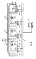
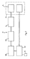
- An embodiment of a production plant according to the invention includes a plurality of functional units 10, in this case roller conveyor units, which are constructed as independent modules and in the manufacturing plant, for example, arranged successively and cooperate, in this case, for example, a cargo 12, such as a workpiece, according to the manufacturing sequence promote.
- functional units 10 in this case roller conveyor units, which are constructed as independent modules and in the manufacturing plant, for example, arranged successively and cooperate, in this case, for example, a cargo 12, such as a workpiece, according to the manufacturing sequence promote.
- a control unit 14 is arranged directly on a frame 11 of the same, which serves on the one hand to control an actuator M serving as an actuator 16 and in this case driving the rollers, wherein the activation of the actuator 16 via signals from sensors 18 takes place which, for example, determine the position of the product 12 along the production line as a function parameter so that a transport of the goods 12 along the individual functional units 10 can be effected according to the actual position of the item 12 and the position of the item 12 required by the production sequence.
- Each of the control units 14 is directly connected to a power supply network 20, which provides the electrical power for the operation of the actuators 16.
- each functional unit 10 is connected to a bus system 22, which allows communication between the individual control units 14.
- a central station 24 is connected to the bus system 22, whose function will be explained in detail below.
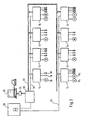
- the individual functional units 10 are not identical to each other, but represent different functional units of the manufacturing plant.
- the manufacturing plant comprises drying units 10T, each of which is provided with a control unit 14T according to the invention, which in this case as a first actuator 16T 1 a blower motor and second Actuator 16T 2 drives an actuator for air dampers and this on the basis of the signal of a detecting sensor 18T, which detects the temperature as a function parameter.
- each dryer unit 10T is additionally assigned a conveyor unit 10F as a functional unit, which can also be controlled via a respective locally assigned control unit 14F, for example in the same way as in principle in connection according to the first embodiment Fig. 1 described.
- both a dryer unit 10T and a conveyor unit 10F are arranged side by side, each equipped with a control unit 14T and 14F according to the present invention and all communicating with each other via the same bus system 22 and also supplied via the same power supply network 20.
- a man-machine interface 30 is provided, which via the LON bus system 22 communicates with the individual control units 14.
- each of these control units 14 is associated with one or more actuators 16 and one or more sensors 18 in order to control the corresponding functional unit 10.
- each control unit is connected to the power supply network 20, which in turn is fed by a central supply station 36.
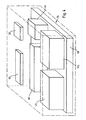
- each of the control units 14 is modular, the basic module of each control unit is a base module 40 to which a variable number of power modules 42 1 and 42 2 are connected.
- a processor module 44 and a variable number of sensor modules 46, corresponding to the number of sensors, are connected to the base module 40.
- control unit 14 An indication of the function and operation of the control unit 14 via a display module 50 and further via an input unit 52 - for example, a handheld terminal in a BUS-external access to the control unit 14 is possible.
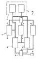
- the base module 40 is provided with a power supply network terminal 54 connected to a power conditioning unit 56.
- the base module 40 is provided with a terminal 58 for the bus system 22, which is connected to a terminal 60 for the processor module 44.
- the processor module 44 is also still connected to a low voltage supply 62 which is powered by the voltage conditioning unit 56.
- the low-voltage supply 62 for example, also supplies a bus controller 64 of an internal bus system 74 of the control unit 14, a terminal 66 of the sensor module 46, a terminal 68 of the display module 50, a terminal 70 of the input unit 52 and connections 72 for the power modules 42.
- Each of the power modules 42 includes, as in FIG Fig. 6 shown, a power electronics 80, which is connected directly to the terminal 72 and thereby also supplied with the corresponding electrical power.
- the power electronics 80 is in turn connected to a terminal 82 for the actuator 16, such as a motor M, in which this the required energy is supplied.
- the power electronics 80 are controlled via a control circuit 84, which is connected to the processor module 44, for example by means of the internal bus system 74, wherein the connection to the internal bus system 74 also takes place via the terminal 72.
- the control circuit 84 controls not only the power electronics 80, but also a supply 86 for a the actuator 16 associated brake relay, wherein the control of this brake relay via the motor terminal 82 takes place.
- phase monitor 88 is provided in each power module 42, which serves to monitor the power electronics 80 supplied electrical energy.
- the phase monitoring 88 is likewise connected to the processor module 44, for example by means of the internal bus system 74, and transmits, for example, the control circuit 84 via this phase information.
- a motor temperature monitor 90 is connected to the motor terminal 82, which also exchanges information about the motor temperature with the processor module 44, for example via the internal bus system 74, with the control circuit 84.
- Each sensor module 46 includes, as in FIG Fig. 7 illustrated, starting from the provided for this connection 72 on the base module 40, a signal conditioning unit 100 which is connected via a sensor terminal 102 to the respective sensor 18 and its signals processed accordingly.
- the signal conditioning unit 100 outputs these signals via a galvanic isolation 103 to the internal bus system 74, which is also connected via the terminal 76 to the control unit 46.
- a direct supply of the sensor terminal 102 with low voltage provided by the base module 40 is provided via the terminal 72.
- the processor module 44 comprises a connection made via the connection 60 with the remaining modules, for example via the internal bus system 74 with a processor unit 110 which comprises, for example, a LON processor which has not only a computer 112 but also a sufficiently large control program memory 114 ,
- the processor unit 110 communicates with a transmitting / receiving unit 116 for the bus system 22, which is connected via the terminal 60 to the bus system 22 and via which thus the communication with the bus system 22 takes place.
- program memory 114 is a function control program set down, which allows to control all functions of the functional unit 10.
Claims (27)
- Installation de fabrication comportant une pluralité d'organes fonctionnels (10) réalisant au moins une fonction, collaborant dans l'installation de fabrication et dont chacun présente au moins un actionneur (16) et au moins un détecteur (18) pour la commande de fonction et/ou la surveillance de fonction, caractérisée en ce que chaque organe fonctionnel (10) présente au moins une unité de commande (14) intelligente exploitant l'organe fonctionnel (10) indépendamment de l'ordinateur central et selon un programme propre de commande de fonction, mémorisé dans une mémoire de programme (114), et qui pilote ledit au moins un actionneur (16) et/ou traite des signaux dudit au moins un détecteur (18) en fonction du programme de commande de fonction,
dans laquelle chaque unité de commande (14) comprend→ un module de puissance (42) pilotant ledit au moins un actionneur (16) et présentant un branchement (82) pour amener à l'actionneur (16) l'énergie nécessaire ainsi qu'une surveillance de phase (88),→ un module détecteur (46) exploitant ledit au moins un détecteur (18), reçoit les signaux de celui-ci et présente un branchement de détecteur (102) pour alimenter le détecteur (18) en basse tension,→ un module de base (40) présentant un branchement (54) pour un réseau d'alimentation en énergie (20) qui est amené à l'unité de commande (14), un branchement (72) pour le module de puissance (42) par lequel le module de puissance (42) est alimenté en énergie électrique, ainsi qu'un branchement (72) pour le module détecteur (46) par lequel le branchement de détecteur (62) est alimenté en basse tension, et→ un module d'entrée/sortie (48) exploitant un organe d'entrée (52), dans laquelle l'organe d'entrée (52) permet d'activer un mode de fonctionnement en cas d'incident de l'unité de commande (14) dans lequel le module de puissance (42) peut être piloté directement. - Installation de fabrication selon la revendication 1, caractérisée en ce que chaque unité de commande (14) exécute de façon autonome la totalité des fonctions prévues avec le programme de commande de fonction.
- Installation de fabrication selon la revendication 1 ou 2, caractérisée en ce que l'unité de commande (14) d'un organe fonctionnel (10) communique directement avec l'unité de commande (14) d'au moins un autre des organes fonctionnels (10).
- Installation de fabrication selon l'une des revendications précédentes, caractérisée en ce que chaque unité de commande (14) saisit tous les paramètres de fonction nécessaires pour la fonction de l'organe fonctionnel (10) et commande en fonction de ces paramètres l'organe fonctionnel (10).
- Installation de fabrication selon l'une des revendications précédentes, caractérisée en ce que toutes les unités de commande (14) de l'installation de fabrication sont reliées à un système de bus (22).
- Installation de fabrication selon la revendication 5, caractérisée en ce que chaque unité de commande (14) est capable de recevoir et d'émettre des signaux de communication par le système de bus (22).
- Installation de fabrication selon la revendication 6, caractérisée en ce que chaque unité de commande (14) est programmable par l'intermédiaire du système de bus (22).
- Installation de fabrication selon la revendication 6 ou 7, caractérisée en ce que le mode de travail de chaque unité de commande (14) est vérifiable par l'intermédiaire du système de bus (22).
- Installation de fabrication selon l'une des revendications 6 à 8, caractérisée en ce que chaque unité de commande (14) émet des annonces d'erreur par l'intermédiaire du système de bus (22).
- Installation de fabrication selon l'une des revendications précédentes, caractérisée par le fait qu'à chaque organe fonctionnel (10) est localement associée l'unité de commande (14).
- Installation de fabrication selon la revendication 10, caractérisée en ce que l'actionneur (16), dont il y a au moins un, et le détecteur (18), dont il y a au moins un, de chaque unité de commande (14) sont directement câblés avec l'organe fonctionnel (10).
- Installation de fabrication selon la revendication 10 ou 11, caractérisée en ce que chaque unité de commande (14) est directement disposée sur l'organe fonctionnel correspondant (10).
- Installation de fabrication selon l'une des revendications 10 à 12, caractérisée en ce que le système de bus (22) est amené à chaque unité de commande associée localement à l'organe fonctionnel (10).
- Installation de fabrication selon l'une des revendications précédentes, caractérisée en ce que chaque unité de commande (14) présente un module processeur (44) intelligent travaillant indépendamment de l'ordinateur central et commandé par le programme de la fonction, le module processeur (44) présentant un organe d'émission et de réception (116) qui réalise une liaison entre un organe processeur (110) du module processeur (44) et un système de bus (22).
- Installation de fabrication selon l'une des revendications 1 à 14, caractérisée en ce que chaque unité de commande (14) présente un module de signalisation (50) intervenant sur une signalisation de la fonction.
- Installation de fabrication selon l'une des revendications 1 à 15, caractérisée en ce qu'en fonctionnement normal, l'organe d'entrée (52) permet de générer des signaux de communication générés par d'autres unités de commande (14) pour l'unité de commande (14) respective.
- Installation de fabrication selon l'une des revendications 1 à 16, caractérisée en ce que l'organe d'entrée (52) permet de signaliser les paramètres de fonction détectés par le détecteur (18).
- Installation de fabrication selon l'une des revendications précédentes, caractérisée en ce que chaque organe fonctionnel (10) forme un tronçon fonctionnel propre de l'installation de fabrication.
- Procédé d'exploitation d'une installation de fabrication comprenant pluralité d'organes fonctionnels (10) réalisant au moins une fonction, collaborant dans l'installation de fabrication et dont chacun présente au moins un actionneur (16) et au moins un détecteur (18) pour la commande de fonction et/ou la surveillance de fonction, caractérisé en ce que chaque organe fonctionnel (10) est exploité par une unité de commande (14) indépendamment de l'ordinateur central et selon un programme propre de commande de fonction, mémorisé dans une mémoire de programme (114), dans lequel l'actionneur (16) est piloté et/ou des signaux du détecteur (18) sont traités en fonction du programme de commande de fonction,
en ce que ledit au moins un actionneur (16) est piloté par un module de puissance (42) de l'unité de commande (14), dans lequel est prévue une surveillance de phase (88) et en ce que l'énergie nécessaire est amenée à l'actionneur (16) par une connexion (82) du module de puissance (42),
en ce que ledit au moins un détecteur (18) est exploité par un module détecteur (46) de l'unité de commande (14) et le détecteur (18) est alimenté en basse tension par l'intermédiaire d'un branchement de détecteur (102) du module détecteur (46),
en ce qu'un module de base (40) de l'unité de commande (14) est relié à un réseau d'alimentation en énergie (20) qui est amené à l'unité de commande (14), le module de puissance (42) est alimenté en énergie électrique par un branchement (72) du module de base (40) et le module détecteur (46) est alimenté en basse tension par un branchement (72) du module de base (40), et
en ce qu'un module d'entrée/sortie (48) de l'unité de commande (14) exploite un organe d'entrée (52), dans lequel, en cas d'incident, un mode de fonc-tionnement en cas d'incident de l'unité de commande (14), dans lequel le module de puissance (42) est piloté directement, est activé par l'organe d'entrée (52). - Procédé selon la revendication 19, caractérisé en ce que dans chaque unité de commande (14) la totalité des fonctions prévues est commandée de façon autonome.
- Procédé selon la revendication 19 ou 20, caractérisé en ce que l'unité de commande (14) respective communique directement avec l'unité de commande (14) d'au moins un autre des organes fonctionnels (10).
- Procédé selon l'une des revendications 19 à 21, caractérisé en ce que chaque unité de commande détecte tous les paramètres de fonction nécessaires à la fonction de l'organe fonctionnel et en ce que l'organe fonctionnel est commandé selon ceux-ci.
- Procédé selon la revendication 22, caractérisé en ce que l'unité de commande détecte une partie des paramètres de fonction par communication directe avec au moins une autre des unités de commande de l'installation de fabrication.
- Procédé selon l'une des revendications 19 à 23, caractérisé en ce que toutes les unités de commande émettent des informations à destination d'un système de bus ou en reçoivent en provenance d'un système de bus.
- Procédé selon la revendication 24, caractérisé en ce que chaque unité de commande peut être programmée par l'intermédiaire du système de bus.
- Procédé selon la revendication 24 ou 25, caractérisé en ce que le mode de travail de chaque unité de commande peut être vérifié par l'intermédiaire du système de bus.
- Procédé selon la revendication 26, caractérisé en ce que des annonces d'erreur sont émises par chaque unité de commande par l'intermédiaire du système de bus.
Priority Applications (1)
| Application Number | Priority Date | Filing Date | Title |
|---|---|---|---|
| DE29724165U DE29724165U1 (de) | 1996-08-13 | 1997-08-04 | Fertigungsanlage |
Applications Claiming Priority (2)
| Application Number | Priority Date | Filing Date | Title |
|---|---|---|---|
| DE19632609A DE19632609A1 (de) | 1996-08-13 | 1996-08-13 | Fertigungsanlage |
| DE19632609 | 1996-08-13 |
Publications (3)
| Publication Number | Publication Date |
|---|---|
| EP0824231A1 EP0824231A1 (fr) | 1998-02-18 |
| EP0824231B1 EP0824231B1 (fr) | 2001-11-14 |
| EP0824231B2 true EP0824231B2 (fr) | 2010-03-17 |
Family
ID=7802520
Family Applications (1)
| Application Number | Title | Priority Date | Filing Date |
|---|---|---|---|
| EP97113438A Expired - Lifetime EP0824231B2 (fr) | 1996-08-13 | 1997-08-04 | Système de fabrication |
Country Status (5)
| Country | Link |
|---|---|
| US (1) | US6256544B1 (fr) |
| EP (1) | EP0824231B2 (fr) |
| BR (1) | BR9706716B1 (fr) |
| DE (2) | DE19632609A1 (fr) |
| ES (1) | ES2167652T5 (fr) |
Families Citing this family (72)
| Publication number | Priority date | Publication date | Assignee | Title |
|---|---|---|---|---|
| SE9801863L (sv) | 1998-05-27 | 1999-11-28 | Abb Ab | Anläggning för styrande av processutrustning |
| US6571273B1 (en) * | 1998-07-13 | 2003-05-27 | Yokogawa Electric Corporation | Process control system |
| DE29813589U1 (de) * | 1998-07-30 | 1999-12-16 | Kuka Schweissanlagen Gmbh | Flexibles Fertigungssystem |
| US6356422B1 (en) * | 1999-11-05 | 2002-03-12 | Siemens Energy & Automation, Inc. | Circuit breaker communication and control system |
| US6785749B2 (en) * | 2000-11-02 | 2004-08-31 | Texas Instruments Incorporated | Apparatus and method for a peripheral inter-module event communication system |
| JP2003099120A (ja) * | 2001-06-27 | 2003-04-04 | Robert Bosch Gmbh | システムの機能性の監視方法,その監視装置,メモリ素子,コンピュータプログラム |
| DE10217646B4 (de) * | 2002-04-19 | 2011-04-14 | Endress + Hauser Gmbh + Co. Kg | Verfahren zur Bestimmung einer charakteristischen Größe eines Prozessmediums |
| US7215088B1 (en) * | 2003-08-26 | 2007-05-08 | Finelite | System and architecture for controlling lighting through a low-voltage bus |
| US7360638B2 (en) * | 2004-08-04 | 2008-04-22 | Siemens Energy & Automation, Inc. | Integrated control card for conveying systems |
| WO2006022569A1 (fr) * | 2004-08-17 | 2006-03-02 | Obshchestvo S Ogranichennoy Otvetstvennostiuy 'promishlennaya Gruppa ' Finprom - Resurs' | Dispositif de commande d'un systeme d'objets par le biais d'une ligne de transport d'energie, et adaptateur associe |
| CN101690019B (zh) | 2007-07-06 | 2014-01-08 | 默勒有限公司 | 通过开放式现场总线控制总线联网的设备的系统和方法 |
| US7818081B2 (en) * | 2008-05-19 | 2010-10-19 | The Procter & Gamble Company | Method for optimizing a manufacturing process having a plurality of interconnected discreet operating stations |
| US9129247B2 (en) * | 2010-05-26 | 2015-09-08 | Amazon Technologies, Inc. | Managing throughput for multiple processes in a materials handling facility |
| US8757363B2 (en) | 2011-05-09 | 2014-06-24 | Insight Automation, Inc. | Conveyor controllers |
| US10652219B2 (en) | 2015-10-28 | 2020-05-12 | Qomplx, Inc. | System and methods for dynamic geospatially-referenced cyber-physical infrastructure inventory and asset management |
| US11025674B2 (en) | 2015-10-28 | 2021-06-01 | Qomplx, Inc. | Cybersecurity profiling and rating using active and passive external reconnaissance |
| US11032323B2 (en) | 2015-10-28 | 2021-06-08 | Qomplx, Inc. | Parametric analysis of integrated operational technology systems and information technology systems |
| US11477245B2 (en) | 2015-10-28 | 2022-10-18 | Qomplx, Inc. | Advanced detection of identity-based attacks to assure identity fidelity in information technology environments |
| US11514531B2 (en) | 2015-10-28 | 2022-11-29 | Qomplx, Inc. | Platform for autonomous risk assessment and quantification for cyber insurance policies |
| US11055601B2 (en) | 2015-10-28 | 2021-07-06 | Qomplx, Inc. | System and methods for creation of learning agents in simulated environments |
| US11005824B2 (en) | 2015-10-28 | 2021-05-11 | Qomplx, Inc. | Detecting and mitigating forged authentication object attacks using an advanced cyber decision platform |
| US20220255926A1 (en) * | 2015-10-28 | 2022-08-11 | Qomplx, Inc. | Event-triggered reauthentication of at-risk and compromised systems and accounts |
| US20200389495A1 (en) | 2015-10-28 | 2020-12-10 | Qomplx, Inc. | Secure policy-controlled processing and auditing on regulated data sets |
| US11323484B2 (en) | 2015-10-28 | 2022-05-03 | Qomplx, Inc. | Privilege assurance of enterprise computer network environments |
| US10783241B2 (en) | 2015-10-28 | 2020-09-22 | Qomplx, Inc. | System and methods for sandboxed malware analysis and automated patch development, deployment and validation |
| US11070592B2 (en) | 2015-10-28 | 2021-07-20 | Qomplx, Inc. | System and method for self-adjusting cybersecurity analysis and score generation |
| US11321637B2 (en) | 2015-10-28 | 2022-05-03 | Qomplx, Inc. | Transfer learning and domain adaptation using distributable data models |
| US11531538B2 (en) | 2015-10-28 | 2022-12-20 | Qomplx, Inc. | Meta-indexing, search, compliance, and test framework for software development using smart contracts |
| US11635994B2 (en) | 2015-10-28 | 2023-04-25 | Qomplx, Inc. | System and method for optimizing and load balancing of applications using distributed computer clusters |
| US11055630B2 (en) | 2015-10-28 | 2021-07-06 | Qomplx, Inc. | Multitemporal data analysis |
| US11757849B2 (en) | 2015-10-28 | 2023-09-12 | Qomplx, Inc. | Detecting and mitigating forged authentication object attacks in multi-cloud environments |
| US10432660B2 (en) | 2015-10-28 | 2019-10-01 | Qomplx, Inc. | Advanced cybersecurity threat mitigation for inter-bank financial transactions |
| US11023284B2 (en) | 2015-10-28 | 2021-06-01 | Qomplx, Inc. | System and method for optimization and load balancing of computer clusters |
| US10740096B2 (en) | 2015-10-28 | 2020-08-11 | Qomplx, Inc. | Meta-indexing, search, compliance, and test framework for software development |
| US11552968B2 (en) | 2015-10-28 | 2023-01-10 | Qomplx, Inc. | System and methods for detecting and mitigating golden SAML attacks against federated services |
| US11968239B2 (en) | 2015-10-28 | 2024-04-23 | Qomplx Llc | System and method for detection and mitigation of data source compromises in adversarial information environments |
| US11074652B2 (en) | 2015-10-28 | 2021-07-27 | Qomplx, Inc. | System and method for model-based prediction using a distributed computational graph workflow |
| US11687527B2 (en) | 2015-10-28 | 2023-06-27 | Qomplx, Inc. | System and method for analysis of graph databases using intelligent reasoning systems |
| US10594714B2 (en) | 2015-10-28 | 2020-03-17 | Qomplx, Inc. | User and entity behavioral analysis using an advanced cyber decision platform |
| US11805106B2 (en) | 2015-10-28 | 2023-10-31 | Qomplx, Inc. | System and method for trigger-based scanning of cyber-physical assets |
| US11595361B2 (en) | 2015-10-28 | 2023-02-28 | Qomplx, Inc. | Geolocation-aware, cyber-enabled inventory and asset management system with automated state prediction capability |
| US11055451B2 (en) | 2015-10-28 | 2021-07-06 | Qomplx, Inc. | System and methods for multi-language abstract model creation for digital environment simulations |
| US11184401B2 (en) | 2015-10-28 | 2021-11-23 | Qomplx, Inc. | AI-driven defensive cybersecurity strategy analysis and recommendation system |
| US10673887B2 (en) | 2015-10-28 | 2020-06-02 | Qomplx, Inc. | System and method for cybersecurity analysis and score generation for insurance purposes |
| US10861014B2 (en) | 2015-10-28 | 2020-12-08 | Qomplx, Inc. | Data monetization and exchange platform |
| US10609079B2 (en) | 2015-10-28 | 2020-03-31 | Qomplx, Inc. | Application of advanced cybersecurity threat mitigation to rogue devices, privilege escalation, and risk-based vulnerability and patch management |
| US11531539B2 (en) | 2015-10-28 | 2022-12-20 | Qomplx, Inc. | Automated compliance and testing framework for software development |
| US10681074B2 (en) | 2015-10-28 | 2020-06-09 | Qomplx, Inc. | System and method for comprehensive data loss prevention and compliance management |
| US11563741B2 (en) * | 2015-10-28 | 2023-01-24 | Qomplx, Inc. | Probe-based risk analysis for multi-factor authentication |
| US11570209B2 (en) | 2015-10-28 | 2023-01-31 | Qomplx, Inc. | Detecting and mitigating attacks using forged authentication objects within a domain |
| US10860951B2 (en) | 2015-10-28 | 2020-12-08 | Qomplx, Inc. | System and method for removing biases within a distributable model |
| US10742647B2 (en) * | 2015-10-28 | 2020-08-11 | Qomplx, Inc. | Contextual and risk-based multi-factor authentication |
| US11757920B2 (en) | 2015-10-28 | 2023-09-12 | Qomplx, Inc. | User and entity behavioral analysis with network topology enhancements |
| US11637866B2 (en) | 2015-10-28 | 2023-04-25 | Qomplx, Inc. | System and method for the secure evaluation of cyber detection products |
| US10860660B2 (en) | 2015-10-28 | 2020-12-08 | Qomplx, Inc. | Method and apparatus for crowdsourced data gathering, extraction, and compensation |
| US11968235B2 (en) | 2015-10-28 | 2024-04-23 | Qomplx Llc | System and method for cybersecurity analysis and protection using distributed systems |
| US10884999B2 (en) | 2015-10-28 | 2021-01-05 | Qomplx, Inc. | Distributable model with biases contained within distributed data |
| US10735456B2 (en) | 2015-10-28 | 2020-08-04 | Qomplx, Inc. | Advanced cybersecurity threat mitigation using behavioral and deep analytics |
| US10917428B2 (en) | 2015-10-28 | 2021-02-09 | Qomplx, Inc. | Holistic computer system cybersecurity evaluation and scoring |
| US10560483B2 (en) | 2015-10-28 | 2020-02-11 | Qomplx, Inc. | Rating organization cybersecurity using active and passive external reconnaissance |
| US11494665B2 (en) | 2015-10-28 | 2022-11-08 | Qomplx, Inc. | Multi-tenant knowledge graph databases with dynamic specification and enforcement of ontological data models |
| US11218510B2 (en) | 2015-10-28 | 2022-01-04 | Qomplx, Inc. | Advanced cybersecurity threat mitigation using software supply chain analysis |
| US11570204B2 (en) | 2015-10-28 | 2023-01-31 | Qomplx, Inc. | Detecting and mitigating golden ticket attacks within a domain |
| US11468368B2 (en) | 2015-10-28 | 2022-10-11 | Qomplx, Inc. | Parametric modeling and simulation of complex systems using large datasets and heterogeneous data structures |
| US11089045B2 (en) | 2015-10-28 | 2021-08-10 | Qomplx, Inc. | User and entity behavioral analysis with network topology enhancements |
| US10970787B2 (en) | 2015-10-28 | 2021-04-06 | Qomplx, Inc. | Platform for live issuance and management of cyber insurance policies |
| US11388198B2 (en) | 2015-10-28 | 2022-07-12 | Qomplx, Inc. | Collaborative database and reputation management in adversarial information environments |
| US10572828B2 (en) | 2015-10-28 | 2020-02-25 | Qomplx, Inc. | Transfer learning and domain adaptation using distributable data models |
| US11297109B2 (en) | 2015-10-28 | 2022-04-05 | Qomplx, Inc. | System and method for cybersecurity reconnaissance, analysis, and score generation using distributed systems |
| EP3208672A1 (fr) * | 2016-02-22 | 2017-08-23 | Airbus Defence and Space GmbH | Systeme de circuit regulateur et son procede de fonctionnement |
| EP3635551A4 (fr) * | 2017-06-07 | 2021-03-10 | Qomplx, Inc. | Analyse prédictive rapide de très grands ensembles de données utilisant un graphe de calcul distribué entraîné par un acteur |
| JP2022168612A (ja) * | 2021-04-26 | 2022-11-08 | シャープ株式会社 | 機器管理システム、機器管理方法、及び機器管理プログラム |
Citations (1)
| Publication number | Priority date | Publication date | Assignee | Title |
|---|---|---|---|---|
| EP0540903A1 (fr) † | 1991-10-11 | 1993-05-12 | Wolfhard Prof. Dr.-Ing. Lawrenz | Elément de commande |
Family Cites Families (7)
| Publication number | Priority date | Publication date | Assignee | Title |
|---|---|---|---|---|
| US4459146A (en) * | 1982-08-18 | 1984-07-10 | Owens-Illinois, Inc. | Electronic control system in a glassware forming machine |
| FR2547520B1 (fr) * | 1983-06-17 | 1985-10-11 | Prodel Maurice | Installation modulaire pour l'assemblage et/ou l'usinage de pieces, avec dispositifs claviers-afficheurs a chaque poste |
| US4672530A (en) * | 1984-12-17 | 1987-06-09 | Combustion Engineering, Inc. | Distributed control with universal program |
| DE3701554A1 (de) * | 1987-01-21 | 1988-08-04 | Duerr Gmbh & Co | Maschinenanlage mit mehreren aktoren |
| US5185866A (en) * | 1988-12-30 | 1993-02-09 | Pitney Bowes Inc. | Dual mode communication among plurality of processors using three distinct data channels each having different function and operations |
| AU4400793A (en) * | 1992-06-12 | 1994-01-04 | Dow Chemical Company, The | Intelligent process control communication system and method |
| DE4225834A1 (de) | 1992-08-05 | 1994-02-10 | Inter Control Koehler Hermann | Speicherprogrammierbare digitale Steuerungseinrichtung |
-
1996
- 1996-08-13 DE DE19632609A patent/DE19632609A1/de not_active Withdrawn
-
1997
- 1997-08-04 EP EP97113438A patent/EP0824231B2/fr not_active Expired - Lifetime
- 1997-08-04 ES ES97113438T patent/ES2167652T5/es not_active Expired - Lifetime
- 1997-08-04 DE DE59705353T patent/DE59705353D1/de not_active Expired - Lifetime
- 1997-08-13 BR BRPI9706716-4A patent/BR9706716B1/pt not_active IP Right Cessation
- 1997-08-13 US US08/910,243 patent/US6256544B1/en not_active Expired - Lifetime
Patent Citations (1)
| Publication number | Priority date | Publication date | Assignee | Title |
|---|---|---|---|---|
| EP0540903A1 (fr) † | 1991-10-11 | 1993-05-12 | Wolfhard Prof. Dr.-Ing. Lawrenz | Elément de commande |
Non-Patent Citations (1)
| Title |
|---|
| "Sicherheit von Werkzeugmaschinen; Transfer- u. Einzweck- oder Sondermaschinen (EU Norm-Entwurf, deutsche Fassung)", ICS 25.080.01, vol. DIN PREN, no. 14070, March 2001 (2001-03-01) - March 2001 (2001-03-01), BEUTH VERLAG GMBH, BERLIN † |
Also Published As
| Publication number | Publication date |
|---|---|
| ES2167652T5 (es) | 2010-07-22 |
| DE19632609A1 (de) | 1998-02-19 |
| US6256544B1 (en) | 2001-07-03 |
| EP0824231B1 (fr) | 2001-11-14 |
| BR9706716B1 (pt) | 2009-05-05 |
| BR9706716A (pt) | 2000-06-06 |
| DE59705353D1 (de) | 2001-12-20 |
| EP0824231A1 (fr) | 1998-02-18 |
| ES2167652T3 (es) | 2002-05-16 |
Similar Documents
| Publication | Publication Date | Title |
|---|---|---|
| EP0824231B2 (fr) | Système de fabrication | |
| DE19718284C2 (de) | Verfahren und Vorrichtung zum Überwachen einer Anlage mit mehreren Funktionseinheiten | |
| EP1589386B1 (fr) | Système de commande de processus | |
| DE4319485C2 (de) | Steuervorrichtung für eine Spinnereimaschine | |
| EP0742499A2 (fr) | Traitement fiable de signaux orientés sûreté | |
| EP0275992A2 (fr) | Parc machine avec plusieurs mobiles | |
| EP1342342B1 (fr) | Configuration automatique d'un reseau | |
| EP0825502B1 (fr) | Système de commande | |
| EP0993698B2 (fr) | Dispositif et procede d'exploitation decentralisee ou de realisation d'une regulation de synchronisme conforme dans un systeme d'entrainement a plusieurs moteurs | |
| EP2098930A1 (fr) | Système de surveillance pour un dispositif d'entraînement | |
| EP3024128B1 (fr) | Commande modulaire d'un entraînement linéaire avec communication | |
| AT14695U1 (de) | Serielles Bussystem mit Koppelmodulen | |
| EP0791874B1 (fr) | Méthode et dispositif de commande de capteurs et/ou actionneurs binaires | |
| DE19911824C2 (de) | Schaltschranküberwachungsanlage | |
| EP1455976B1 (fr) | Reglage d'ouverture d'entree de segments d'installations de coulee continue | |
| EP2835699B1 (fr) | Dispositif et procédé de configuration et/ou de programmation d'un contrôleur de sécurité | |
| EP1903530B1 (fr) | Agencement doté d'un appareil sous vide et son procédé de fonctionnement | |
| DE3522220C2 (de) | Schaltungsanordnung zur sicheren Ansteuerung von Stellelementen eines Prozesses | |
| WO1998001302A1 (fr) | Systeme de serigraphie rotatif | |
| EP2092398B1 (fr) | Appareil de terrain bifilaire pour la technique d'automatisation de procédés destinée à connecter au moins un élément de capteur | |
| EP0647890B1 (fr) | Module de calcul pour un système d'automatisation modulaire | |
| EP2315090B1 (fr) | Méthode de commande en temps réel pour un dispositif de commande d'un processus industriel et méthode de commande en temps réel pour un ordinateur | |
| EP1620767B1 (fr) | Procede pour moderniser une installation technique et element d'entrainement adapte a cet effet | |
| DE102012025228A1 (de) | Steuerungsübergreifende Energieverwaltung in einer Anlage | |
| EP0375958B1 (fr) | Dispositif à relier les unités additionnelles |
Legal Events
| Date | Code | Title | Description |
|---|---|---|---|
| PUAI | Public reference made under article 153(3) epc to a published international application that has entered the european phase |
Free format text: ORIGINAL CODE: 0009012 |
|
| AK | Designated contracting states |
Kind code of ref document: A1 Designated state(s): DE ES FR GB IT |
|
| AX | Request for extension of the european patent |
Free format text: AL;LT;LV;RO;SI |
|
| 17P | Request for examination filed |
Effective date: 19980817 |
|
| AKX | Designation fees paid |
Free format text: DE ES FR GB IT |
|
| RBV | Designated contracting states (corrected) |
Designated state(s): DE ES FR GB IT |
|
| 17Q | First examination report despatched |
Effective date: 19981229 |
|
| GRAG | Despatch of communication of intention to grant |
Free format text: ORIGINAL CODE: EPIDOS AGRA |
|
| GRAG | Despatch of communication of intention to grant |
Free format text: ORIGINAL CODE: EPIDOS AGRA |
|
| GRAH | Despatch of communication of intention to grant a patent |
Free format text: ORIGINAL CODE: EPIDOS IGRA |
|
| RAP1 | Party data changed (applicant data changed or rights of an application transferred) |
Owner name: DUERR AUTOMOTION GMBH Owner name: DUERR SYSTEMS GMBH |
|
| GRAH | Despatch of communication of intention to grant a patent |
Free format text: ORIGINAL CODE: EPIDOS IGRA |
|
| GRAA | (expected) grant |
Free format text: ORIGINAL CODE: 0009210 |
|
| AK | Designated contracting states |
Kind code of ref document: B1 Designated state(s): DE ES FR GB IT |
|
| REF | Corresponds to: |
Ref document number: 59705353 Country of ref document: DE Date of ref document: 20011220 |
|
| REG | Reference to a national code |
Ref country code: GB Ref legal event code: IF02 |
|
| GBT | Gb: translation of ep patent filed (gb section 77(6)(a)/1977) |
Effective date: 20020122 |
|
| ET | Fr: translation filed | ||
| REG | Reference to a national code |
Ref country code: ES Ref legal event code: FG2A Ref document number: 2167652 Country of ref document: ES Kind code of ref document: T3 |
|
| PLBQ | Unpublished change to opponent data |
Free format text: ORIGINAL CODE: EPIDOS OPPO |
|
| PLBI | Opposition filed |
Free format text: ORIGINAL CODE: 0009260 |
|
| PLBF | Reply of patent proprietor to notice(s) of opposition |
Free format text: ORIGINAL CODE: EPIDOS OBSO |
|
| 26 | Opposition filed |
Opponent name: GROB-WERKE BURKHART GROB E.K. Effective date: 20020805 |
|
| PLBF | Reply of patent proprietor to notice(s) of opposition |
Free format text: ORIGINAL CODE: EPIDOS OBSO |
|
| PLAY | Examination report in opposition despatched + time limit |
Free format text: ORIGINAL CODE: EPIDOSNORE2 |
|
| PLAP | Information related to despatch of examination report in opposition + time limit deleted |
Free format text: ORIGINAL CODE: EPIDOSDORE2 |
|
| PLAY | Examination report in opposition despatched + time limit |
Free format text: ORIGINAL CODE: EPIDOSNORE2 |
|
| PLAH | Information related to despatch of examination report in opposition + time limit modified |
Free format text: ORIGINAL CODE: EPIDOSCORE2 |
|
| PLBC | Reply to examination report in opposition received |
Free format text: ORIGINAL CODE: EPIDOSNORE3 |
|
| PLAH | Information related to despatch of examination report in opposition + time limit modified |
Free format text: ORIGINAL CODE: EPIDOSCORE2 |
|
| PLAY | Examination report in opposition despatched + time limit |
Free format text: ORIGINAL CODE: EPIDOSNORE2 |
|
| PLBC | Reply to examination report in opposition received |
Free format text: ORIGINAL CODE: EPIDOSNORE3 |
|
| RAP2 | Party data changed (patent owner data changed or rights of a patent transferred) |
Owner name: DUERR SYSTEMS GMBH |
|
| PLAH | Information related to despatch of examination report in opposition + time limit modified |
Free format text: ORIGINAL CODE: EPIDOSCORE2 |
|
| PLAT | Information related to reply to examination report in opposition deleted |
Free format text: ORIGINAL CODE: EPIDOSDORE3 |
|
| PLAH | Information related to despatch of examination report in opposition + time limit modified |
Free format text: ORIGINAL CODE: EPIDOSCORE2 |
|
| PLBP | Opposition withdrawn |
Free format text: ORIGINAL CODE: 0009264 |
|
| RTI2 | Title (correction) |
Free format text: MANUFACTURING SYSTEM |
|
| PUAH | Patent maintained in amended form |
Free format text: ORIGINAL CODE: 0009272 |
|
| STAA | Information on the status of an ep patent application or granted ep patent |
Free format text: STATUS: PATENT MAINTAINED AS AMENDED |
|
| RAP2 | Party data changed (patent owner data changed or rights of a patent transferred) |
Owner name: DUERR SYSTEMS GMBH |
|
| 27A | Patent maintained in amended form |
Effective date: 20100317 |
|
| AK | Designated contracting states |
Kind code of ref document: B2 Designated state(s): DE ES FR GB IT |
|
| REG | Reference to a national code |
Ref country code: ES Ref legal event code: DC2A Date of ref document: 20100616 Kind code of ref document: T5 |
|
| REG | Reference to a national code |
Ref country code: FR Ref legal event code: TP |
|
| PGFP | Annual fee paid to national office [announced via postgrant information from national office to epo] |
Ref country code: IT Payment date: 20100826 Year of fee payment: 14 |
|
| PGFP | Annual fee paid to national office [announced via postgrant information from national office to epo] |
Ref country code: GB Payment date: 20100819 Year of fee payment: 14 |
|
| GBPC | Gb: european patent ceased through non-payment of renewal fee |
Effective date: 20110804 |
|
| PG25 | Lapsed in a contracting state [announced via postgrant information from national office to epo] |
Ref country code: IT Free format text: LAPSE BECAUSE OF NON-PAYMENT OF DUE FEES Effective date: 20110804 |
|
| PG25 | Lapsed in a contracting state [announced via postgrant information from national office to epo] |
Ref country code: GB Free format text: LAPSE BECAUSE OF NON-PAYMENT OF DUE FEES Effective date: 20110804 |
|
| PGFP | Annual fee paid to national office [announced via postgrant information from national office to epo] |
Ref country code: ES Payment date: 20130816 Year of fee payment: 17 Ref country code: DE Payment date: 20130821 Year of fee payment: 17 |
|
| PGFP | Annual fee paid to national office [announced via postgrant information from national office to epo] |
Ref country code: FR Payment date: 20130823 Year of fee payment: 17 |
|
| REG | Reference to a national code |
Ref country code: DE Ref legal event code: R119 Ref document number: 59705353 Country of ref document: DE |
|
| REG | Reference to a national code |
Ref country code: DE Ref legal event code: R119 Ref document number: 59705353 Country of ref document: DE Effective date: 20150303 |
|
| REG | Reference to a national code |
Ref country code: FR Ref legal event code: ST Effective date: 20150430 |
|
| PG25 | Lapsed in a contracting state [announced via postgrant information from national office to epo] |
Ref country code: DE Free format text: LAPSE BECAUSE OF NON-PAYMENT OF DUE FEES Effective date: 20150303 |
|
| PG25 | Lapsed in a contracting state [announced via postgrant information from national office to epo] |
Ref country code: FR Free format text: LAPSE BECAUSE OF NON-PAYMENT OF DUE FEES Effective date: 20140901 |
|
| REG | Reference to a national code |
Ref country code: ES Ref legal event code: FD2A Effective date: 20150925 |
|
| PG25 | Lapsed in a contracting state [announced via postgrant information from national office to epo] |
Ref country code: ES Free format text: LAPSE BECAUSE OF NON-PAYMENT OF DUE FEES Effective date: 20140805 |