EP0824202B1 - Kupplungsmethode und Kupplungsvorrichtung - Google Patents
Kupplungsmethode und Kupplungsvorrichtung Download PDFInfo
- Publication number
- EP0824202B1 EP0824202B1 EP97306096A EP97306096A EP0824202B1 EP 0824202 B1 EP0824202 B1 EP 0824202B1 EP 97306096 A EP97306096 A EP 97306096A EP 97306096 A EP97306096 A EP 97306096A EP 0824202 B1 EP0824202 B1 EP 0824202B1
- Authority
- EP
- European Patent Office
- Prior art keywords
- adapting
- bolt
- sleeve element
- flanges
- sleeve
- Prior art date
- Legal status (The legal status is an assumption and is not a legal conclusion. Google has not performed a legal analysis and makes no representation as to the accuracy of the status listed.)
- Expired - Lifetime
Links
- 230000008878 coupling Effects 0.000 title claims description 11
- 238000010168 coupling process Methods 0.000 title claims description 11
- 238000005859 coupling reaction Methods 0.000 title claims description 11
- 238000000034 method Methods 0.000 title claims description 9
- 230000005540 biological transmission Effects 0.000 description 2
- 238000005452 bending Methods 0.000 description 1
- 238000012986 modification Methods 0.000 description 1
- 230000004048 modification Effects 0.000 description 1
Images

Classifications
-
- F—MECHANICAL ENGINEERING; LIGHTING; HEATING; WEAPONS; BLASTING
- F16—ENGINEERING ELEMENTS AND UNITS; GENERAL MEASURES FOR PRODUCING AND MAINTAINING EFFECTIVE FUNCTIONING OF MACHINES OR INSTALLATIONS; THERMAL INSULATION IN GENERAL
- F16D—COUPLINGS FOR TRANSMITTING ROTATION; CLUTCHES; BRAKES
- F16D1/00—Couplings for rigidly connecting two coaxial shafts or other movable machine elements
- F16D1/06—Couplings for rigidly connecting two coaxial shafts or other movable machine elements for attachment of a member on a shaft or on a shaft-end
- F16D1/08—Couplings for rigidly connecting two coaxial shafts or other movable machine elements for attachment of a member on a shaft or on a shaft-end with clamping hub; with hub and longitudinal key
- F16D1/0876—Couplings for rigidly connecting two coaxial shafts or other movable machine elements for attachment of a member on a shaft or on a shaft-end with clamping hub; with hub and longitudinal key with axial keys and no other radial clamping
- F16D1/0882—Couplings for rigidly connecting two coaxial shafts or other movable machine elements for attachment of a member on a shaft or on a shaft-end with clamping hub; with hub and longitudinal key with axial keys and no other radial clamping the key being axially tapered and tightening when loaded axially
- F16D1/0888—Couplings for rigidly connecting two coaxial shafts or other movable machine elements for attachment of a member on a shaft or on a shaft-end with clamping hub; with hub and longitudinal key with axial keys and no other radial clamping the key being axially tapered and tightening when loaded axially the key having two axially tapered interengaging parts
-
- F—MECHANICAL ENGINEERING; LIGHTING; HEATING; WEAPONS; BLASTING
- F16—ENGINEERING ELEMENTS AND UNITS; GENERAL MEASURES FOR PRODUCING AND MAINTAINING EFFECTIVE FUNCTIONING OF MACHINES OR INSTALLATIONS; THERMAL INSULATION IN GENERAL
- F16B—DEVICES FOR FASTENING OR SECURING CONSTRUCTIONAL ELEMENTS OR MACHINE PARTS TOGETHER, e.g. NAILS, BOLTS, CIRCLIPS, CLAMPS, CLIPS OR WEDGES; JOINTS OR JOINTING
- F16B3/00—Key-type connections; Keys
- F16B3/06—Key-type connections; Keys using taper sleeves
-
- F—MECHANICAL ENGINEERING; LIGHTING; HEATING; WEAPONS; BLASTING
- F16—ENGINEERING ELEMENTS AND UNITS; GENERAL MEASURES FOR PRODUCING AND MAINTAINING EFFECTIVE FUNCTIONING OF MACHINES OR INSTALLATIONS; THERMAL INSULATION IN GENERAL
- F16B—DEVICES FOR FASTENING OR SECURING CONSTRUCTIONAL ELEMENTS OR MACHINE PARTS TOGETHER, e.g. NAILS, BOLTS, CIRCLIPS, CLAMPS, CLIPS OR WEDGES; JOINTS OR JOINTING
- F16B2200/00—Constructional details of connections not covered for in other groups of this subclass
- F16B2200/50—Flanged connections
- F16B2200/506—Flanged connections bolted or riveted
-
- Y—GENERAL TAGGING OF NEW TECHNOLOGICAL DEVELOPMENTS; GENERAL TAGGING OF CROSS-SECTIONAL TECHNOLOGIES SPANNING OVER SEVERAL SECTIONS OF THE IPC; TECHNICAL SUBJECTS COVERED BY FORMER USPC CROSS-REFERENCE ART COLLECTIONS [XRACs] AND DIGESTS
- Y10—TECHNICAL SUBJECTS COVERED BY FORMER USPC
- Y10T—TECHNICAL SUBJECTS COVERED BY FORMER US CLASSIFICATION
- Y10T403/00—Joints and connections
- Y10T403/16—Joints and connections with adjunctive protector, broken parts retainer, repair, assembly or disassembly feature
- Y10T403/1633—Utilizing fluid pressure
-
- Y—GENERAL TAGGING OF NEW TECHNOLOGICAL DEVELOPMENTS; GENERAL TAGGING OF CROSS-SECTIONAL TECHNOLOGIES SPANNING OVER SEVERAL SECTIONS OF THE IPC; TECHNICAL SUBJECTS COVERED BY FORMER USPC CROSS-REFERENCE ART COLLECTIONS [XRACs] AND DIGESTS
- Y10—TECHNICAL SUBJECTS COVERED BY FORMER USPC
- Y10T—TECHNICAL SUBJECTS COVERED BY FORMER US CLASSIFICATION
- Y10T403/00—Joints and connections
- Y10T403/70—Interfitted members
- Y10T403/7047—Radially interposed shim or bushing
- Y10T403/7051—Wedging or camming
- Y10T403/7052—Engaged by axial movement
- Y10T403/7056—Threaded actuator
Definitions
- This invention relates to a method in accordance with the preamble of claim 1 for coupling together flanged members and to a coupling arrangement.
- DE-A-3 507 452 discloses a coupling having elements providing a closed bore in which a tapered bolt and sleeve element are received. However this coupling does not have means for facilitating decoupling of the bolt and sleeve element.
- An aim of the present invention is to create a novel solution for coupling together two flanged members, e.g. two flanged shaft parts, by means of a flange joint where the bore of one flange is closed at the bottom but which, however, uses tapered surfaces so that the shaft joint is thus especially suitable for the transmission of a large axial torque force.
- the invention is particularly, but not exclusively, directed to couplings to be applied to the crankshafts or camshafts of large diesel engines.
- a further aim of the invention is to provide a coupling which is constructionally simple and reliable and the assembly and disassembly of which is as simple, and takes up as little time, as possible.
- end piece may also be provided with means for preventing turning of the end piece relative to the adapting bolt.
- the compressing of the adapting bolt tightly to the sleeve element can with advantage be accomplished hydraulically.
- a separate cylindrical supporting sleeve is supported against the sleeve element and a piston member, hydraulically movable relative to the supporting sleeve, is screw-threadedly connected to the adapting bolt.
- the compressing can be accomplished mechanically by utilizing a tightening screw bolt screw-threadedly connected to the adapting bolt and a support piece arranged between the tightening screw bolt and the sleeve element and supported against the sleeve element.
- the through-going hole in the adapting bolt is conveniently provided with threads, at least at the narrower end of the adapting bolt, for connection to axial force transmitting means.
- each adapting bolt is advantageously shorter than the combined thickness of the flanges.
- the tapered surface of each bolt preferably extends over the entire length of the adapting bolt.
- the adapting bolt and associated sleeve element can, with advantage, be of substantially equal length. In this way the flange joint requires as little space as possible.
- the hole in the end piece may be provided with threads to enable connection thereto of a detaching tool for the joint. If the end piece is further provided with means, for example a pin, to prevent turning of the end piece relative to the adapting bolt, detachment of the joint can be accomplished relatively simply and quickly.
- reference numerals 1 and 2 indicate end flanges of flanged shafts to be joined end to end.
- the flange 1 includes a number of through-going bores 1a (only one of which is shown in each figure) and the flange 2 has a corresponding number of bores 2a aligned with the bores 1a and each having a closed bottom.
- a sleeve element 3 which encloses an adapting bolt 4.
- the sleeve element 3 and bolt 4 are fastened together by utilizing respective tapered counter surfaces 3a and 4a, the tapering of which surfaces has been exaggerated for clarity in the figures.
- the adapting bolt 4 has an axial, through-going hole 5, one end of which includes screw threads 5a.
- the narrower end of the tapered bolt 4 is positioned to the same side (i.e. to the left as shown in the figures) as the flange 1 of the two flanges.
- hydraulic means are used to assemble the joint.
- the hydraulic means include a supporting sleeve 6 supported against the outer end of the sleeve element 3, and a piston member 7 which has a screw-threaded pin part 7a screw-threadedly connected to the screw threads 5a of the hole 5 in the adapting bolt 4.
- the piston member 7 includes a passage 8 for feeding hydraulic medium under pressure from a feeding device (not shown) into a chamber 9 between the piston member 7 and the supporting sleeve 6.
- the creation of a secure joint between the adapting bolt 4 and the sleeve element 3 is provided mechanically by using a tightening screw bolt 12.
- the bolt 12 is screw-threadedly connected co the screw threads 5a of the hole 5 in the adapting bolt 4 and a support piece 13 is positioned between the tightening screw bolt 12 and the sleeve element 3 and is supported against the sleeve element 3.
- the tightening screw bolt 12 passes through a hole 13a in the support piece 13, whereby the assembling of the joint is easily carried out by turning the tightening screw bolt 12.
- the parts 12 and 13 can be either left in place or removed according to need.
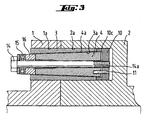
- Figure 3 illustrates the joint being dissembled.
- a separate end piece 10 at the inner end of the sleeve element 3 in the bores 1a and 2a.
- the end piece 10 has a through-going hole 10a axially aligned with the hole 5 and has screw threads 10b.
- the end piece 10 is also provided with a cavity 10c which allows movement of the adapting bolt 4 axially to the right in Figure 3 to detach the adapting bolt 4 from the sleeve element 3.
- the means providing the actual movement of relocation comprises an arrangement including a screw bolt 14 having a pin part 14a which extends through the hole 5 for screw-threaded connection to the screw threads 10b of the hole 10a, a support piece 16 supported against the adapting bolt 4 and a thrust bearing 15 which makes it possible for the screw bolt 14 to be turned relative to the support piece 16.
- the arrangement further includes a pin 11 which prevents the end piece 10 from turning relative to the adapting bolt 4. The dissembling of the joint again takes place simply by turning the screw bolt 14, as a consequence of which the adapting bolt 4 moves relative to the sleeve element 3 (to the right in Figure 3) into the cavity 10c of the end piece 10.
Claims (9)
- Verfahren zum Aneinanderkuppeln zweier mit Flansch versehener Glieder, zum Beispiel Wellen, unter Verwendung sich anpassender Kegelschrauben (4) und damit zusammenwirkender zylindrischer Hülsenelemente (3) mit sich verjüngenden Innenflächen (3a), die den sich anpassenden Kegelschrauben (4) entsprechen, wobei die sich anpassenden Schrauben (4) und die Hülsenelemente (3) in miteinander fluchtenden Bohrungen (1a, 2a) in Flanschen (1, 2) der mit Flanschen versehenen Glieder angeordnet sind, wobei eine Bohrung jedes Paars miteinander fluchtender Bohrungen eine Durchgangsbohrung (1a) ist, wobei das Verfahren folgende Schritte umfaßt: Anordnen jeder sich anpassenden Schraube (4) in dem ihr zugeordneten Hülsenelement (3) und Unterbringen jeder Schraube und jedes Hülsenelements, die zusammenwirken, in den zugehörigen miteinander fluchtenden Bohrungen (1a, 2a) in den Flanschen, und für jede sich anpassende Schraube (4) und jedes damit zusammenwirkende Hülsenelement (3) ihr axiales Aneinanderpressen, so daß eine Zugkraft auf die sich anpassende Schraube (4) ausgeübt wird, dadurch gekennzeichnet, daß das Aneinanderpressen jeder sich anpassenden Schraube (4) und des mit ihr zusammenwirkenden Hülsenelements (3) mit Hilfe eines in der Position der Achse der sich anpassenden Schraube (4) angeordneten Durchgangslochs (5) erreicht wird, wobei die Endfläche des Hülsenelements (3) als Stütze für die erforderliche Gegenkraft verwendet wird, und weiterhin mit den Schritten des derartigen Anordnens jeder sich anpassenden Schraube (4) in dem ihr zugeordneten Hülsenelement (3), daß sich das schmalere Ende der sich anpassenden Kegelschraube (4) auf der gleichen Seite wie das des Flanschs der beiden Flansche befindet, in dem die Durchgangsbohrung (1a) ausgebildet ist, und des Anordnens eines getrennten Endstücks (10), das mit einem Durchgangsloch (10a) versehen ist, das sich in der Position der Achse des Hülsenelements (3) am Ende des Hülsenelements (3) befindet, wobei das Endstück neben dem Grund der anderen Bohrung (2a) bleibt, deren unteres Ende geschlossen ist, und eine Bewegung der sich anpassenden Schraube (4) in Axialrichtung bezüglich des Endstücks (10) gestattet, um ein Lösen der sich anpassenden Schraube (4) von dem Hülsenelement (3) zu ermöglichen.
- Verfahren nach Anspruch 1, dadurch gekennzeichnet, daß in Schritt (a) das Endstück (10) zusätzlich mit einem Mittel (11) zur Verhinderung des Drehens des Endstücks (10) bezüglich der sich anpassenden Schraube (4) versehen ist.
- Verfahren nach Anspruch 1 oder 2, dadurch gekennzeichnet, daß das Aneinanderpressen hydraulisch erreicht wird, wobei eine getrennte zylindrische Stützhülse (6) gegen das Hülsenelement (3) gestützt wird, und ein in das Loch (5) der sich anpassenden Schraube (4) geschraubtes Kolbenglied (7) bezüglich der Stützhülse (6) hydraulisch beweglich ist.
- Verfahren nach Anspruch 1 oder 2, dadurch gekennzeichnet, daß das Aneinanderpressen mechanisch erreicht wird, indem ein Festziehschraubbolzen (12) in das Loch (5) der sich anpassenden Schraube (4) geschraubt und ein Stützteil (13) zwischen dem Festziehschraubbolzen (12) und dem Hülsenelement (3) angeordnet und am Hülsenelement (3) abgestützt wird.
- Verbindungsanordnung mit zwei miteinander verbundenen Gliedern, die jeweils mit einem Flansch (1, 2) mit darin ausgebildeten Bohrungen (1a, 2a) versehen sind, wobei die miteinander verbundenen Glieder Flansch an Flansch angeordnet sind und die Bohrungen (1a, 2a) in den beiden Flanschen miteinander fluchten, wobei eine Bohrung (1a) jedes fluchtenden Paars Bohrungen eine Durchgangsbohrung (1a) ist, wobei sich anpassende Kegelschrauben (4) und damit zusammenwirkende zylindrische Hülsenelemente (3) eine sich verjüngende Innenfläche (3a) aufweisen, die den sich anpassenden Kegelschrauben (4) entspricht, wobei die sich anpassenden Schrauben (4) und die Hülsenelemente (3) in den fluchtenden Bohrungen (1a, 2a) in den Flanschen angeordnet sind, wobei jede sich anpassende Schraube (4) in dem ihr zugeordneten Hülsenelement (3) angeordnet ist und jedes zusammenwirkende Schrauben- und Hülsenelementpaar in den ihm zugeordneten fluchtenden Bohrungen (1a, 2a) in den Flanschen untergebracht ist, dadurch gekennzeichnet, daß die andere Bohrung (2a) jedes Paars fluchtender Bohrungen eine geschlossene Bohrung ist, daß jede sich anpassende Schraube (4) in dem ihr zugeordneten Hülsenelement (3) so angeordnet ist, daß sich das schmalere Ende der sich anpassenden Kegelschraube (4) auf der gleichen Seite wie das des Flanschs der beiden Flansche befindet, in dem die Durchgangsbohrung (1a) ausgebildet ist, daß jede sich anpassende Schraube (4) mit einem axialen Durchgangsloch (5) versehen ist, um die gegenseitige Befestigung der sich anpassenden Schraube (4) an dem ihr zugeordneten Hülsenelement (3) und die Befestigung beider in den Bohrungen (1a, 2a) der Flansche zu gewährleisten, und daß für jedes Paar miteinander fluchtender Bohrungen (1a, 2a) am Ende des Hülsenelements (3) neben dem Grund der geschlossenen Bohrung (2a) ein getrenntes Endstück (10) vorgesehen ist, das mit einem konzentrisch zum Durchgangsloch (5) in der sich anpassenden Schraube (4) verlaufenden Loch (10a) versehen ist, das so angeordnet ist, daß es eine Bewegung der sich anpassenden Schraube (4) in Axialrichtung zum Grund der Bohrungen (1a 2a) hin gestattet, um ein Lösen der sich anpassenden Schraube (4) vom Hülsenelement (3) zu ermöglichen.
- Anordnung nach Anspruch 5, dadurch gekennzeichnet, daß das Loch (5) in der sich anpassenden Schraube (4) zumindest an deren schmaleren Ende mit einem Gewinde (5a) zur Verbindung mit Axialkraftübertragungsmitteln (7, 7a, 12) versehen ist.
- Anordnung nach Anspruch 5 oder 6, dadurch gekennzeichnet, daß jede sich anpassende Schraube (4) kürzer ist als die kombinierte Dicke der beiden Flansche (1, 2) und daß die sich verjüngende Fläche (4a) jeder sich anpassenden Schraube über deren ganze Länge verläuft.
- Anordnung nach einem der Ansprüche 5 bis 7, dadurch gekennzeichnet, daß jede sich anpassende Schraube (4) und das ihr zugeordnete zusammenwirkende Hülsenelement (3) im wesentlichen die gleiche Länge aufweisen.
- Anordnung nach einem der Ansprüche 5 bis 8, dadurch gekennzeichnet, daß das Loch (10a) im Endstück, mit einem Gewinde (10b) zur Verbindung eines Lösewerkzeugs (14, 14a) für die Verbindung versehen ist.
Applications Claiming Priority (2)
| Application Number | Priority Date | Filing Date | Title |
|---|---|---|---|
| FI963172A FI108157B (fi) | 1996-08-13 | 1996-08-13 | Kytkentämenetelmä ja laite |
| FI963172 | 1996-08-13 |
Publications (3)
| Publication Number | Publication Date |
|---|---|
| EP0824202A2 EP0824202A2 (de) | 1998-02-18 |
| EP0824202A3 EP0824202A3 (de) | 1999-05-06 |
| EP0824202B1 true EP0824202B1 (de) | 2002-10-16 |
Family
ID=8546484
Family Applications (1)
| Application Number | Title | Priority Date | Filing Date |
|---|---|---|---|
| EP97306096A Expired - Lifetime EP0824202B1 (de) | 1996-08-13 | 1997-08-11 | Kupplungsmethode und Kupplungsvorrichtung |
Country Status (5)
| Country | Link |
|---|---|
| US (1) | US6039497A (de) |
| EP (1) | EP0824202B1 (de) |
| JP (1) | JPH1078042A (de) |
| DE (1) | DE69716364T2 (de) |
| FI (1) | FI108157B (de) |
Families Citing this family (17)
| Publication number | Priority date | Publication date | Assignee | Title |
|---|---|---|---|---|
| US6390723B1 (en) * | 1996-10-05 | 2002-05-21 | Schaefer Erhard | Changing device for shaft/hub connections |
| DE19906168C1 (de) * | 1999-02-08 | 2000-09-21 | Atec Weiss Gmbh & Co Kg | Konusschraubverbindung für Lamellenpaket-Wellenkupplungen |
| DE20119641U1 (de) * | 2001-12-04 | 2002-02-28 | Sauer Achsenfab | Radlagerung an einem Achskörper für Fahrzeuge |
| EP2070065A2 (de) * | 2006-09-11 | 2009-06-17 | National-Oilwell Varco, L.P. | Rfid-etikettanordnung |
| FI120889B (fi) * | 2007-03-08 | 2010-04-15 | Waertsilae Finland Oy | Liitosjärjestely ja siihen kuuluva lukituspultti |
| CN101337340B (zh) * | 2007-07-06 | 2011-06-08 | 鸿富锦精密工业(深圳)有限公司 | 夹紧装置 |
| NO337432B1 (no) * | 2007-11-12 | 2016-04-11 | Bolt Norge As | Anordning ved spennbolt |
| DE202008013896U1 (de) * | 2008-10-17 | 2010-03-11 | Liebherr-Hydraulikbagger Gmbh | Verfahrbares Arbeitsgerät |
| FR2947596B1 (fr) * | 2009-07-06 | 2015-09-25 | Airbus Operations Sas | Insert taraude pour alesage cylindrique et equipement d'installation d'un tel insert |
| KR101718134B1 (ko) * | 2012-03-06 | 2017-04-04 | 테크노패스트 인더스트리즈 피티와이 리미티드 | 고용량 라디얼 핏 커플링 볼트 |
| DE102012007522A1 (de) * | 2012-04-17 | 2013-10-17 | Robert Bosch Gmbh | Antriebssystem zum Antrieb einer Walze und Verfahren zum Herstellen des Antriebssystems |
| EP2837840B1 (de) * | 2013-08-15 | 2016-06-22 | ALSTOM Technology Ltd | Wellenkupplunganordnung und Verfahren zum Kuppeln von Wellen |
| US10520120B2 (en) * | 2014-03-24 | 2019-12-31 | Ameriforge Group Inc. | Drilling riser flanges and assemblies with contoured bearing surfaces to reduce shear in connectors |
| US10014739B2 (en) | 2014-03-25 | 2018-07-03 | Trane International Inc. | Methods and systems to mount a rotor to a shaft |
| EP2933513A1 (de) | 2014-04-15 | 2015-10-21 | Siemens Aktiengesellschaft | Kupplungsvorrichtung zur Anbindung einer Schaltkupplung an einen Turbinenstrang |
| JP6933301B2 (ja) * | 2018-05-24 | 2021-09-08 | 株式会社Ihi | 回転体、および、過給機 |
| JP7443384B2 (ja) * | 2018-10-15 | 2024-03-05 | ノルト‐ロック・スウィッツァランド・ゲー・エム・ベー・ハー | 膨張ファスナ用の液圧式の緊張および解放工具 |
Family Cites Families (15)
| Publication number | Priority date | Publication date | Assignee | Title |
|---|---|---|---|---|
| US1960045A (en) * | 1930-12-19 | 1934-05-22 | Glasfabrik Sophienhutte Richar | Process for the manufacture of doublewalled flasks |
| GB817028A (en) * | 1956-10-15 | 1959-07-22 | Det Danske Staalvalsevaerk As | Means for connecting a coupling head to a trunnion |
| CS173169B1 (de) * | 1973-10-29 | 1977-02-28 | ||
| SE389076B (sv) * | 1975-08-27 | 1976-10-25 | Eriksbergs Mek Verk | Flensforband, speciellt for propelleraxeln pa fartyg |
| GB1527956A (en) * | 1976-03-05 | 1978-10-11 | Ringfeeder Gmbh | Demountable clamping set for connecting a shaft to a hub |
| US4089613A (en) * | 1977-02-09 | 1978-05-16 | Caterpillar Tractor Co. | Eccentric pin and bushing means for mounting misaligned components |
| US4192621A (en) | 1978-09-26 | 1980-03-11 | Ab Gothenburg Motor | Method for interconnecting two shaft-ends and a shaft coupling made in accordance with said method |
| FR2483548A1 (fr) * | 1980-05-28 | 1981-12-04 | Alsthom Atlantique | Dispositif d'accouplement entre deux rotors |
| AT380935B (de) * | 1980-12-11 | 1986-07-25 | Durand Francois | Kupplung zur reibschluessigen drehverbindung von maschinenteilen, wie z.b. nabe und welle |
| DE3507452C1 (de) * | 1985-03-02 | 1986-01-02 | Oskar E. 7129 Brackenheim Peter | Spannsatz zur Verbindung von Wellen mit Naben |
| WO1988002074A1 (en) * | 1986-09-09 | 1988-03-24 | Pilgrim Engineering Developments Limited | Bolted coupling |
| DD299201A5 (de) * | 1990-09-27 | 1992-04-02 | ����@�����@�����@����k�� | Verbindungseinrichtung fuer ein insbesondere rohrfoermiges bauteil |
| NO175017C (no) * | 1992-04-03 | 1994-08-17 | Arne Aarre | Dreieledd |
| DE9403481U1 (de) * | 1994-03-02 | 1995-06-29 | Muellenberg Ralph | Spannanordnung mit einem Konusspannbolzen |
| US5649778A (en) * | 1996-05-28 | 1997-07-22 | Lin; Wei-Hwang | Multi-directional hydraulic swivel joint |
-
1996
- 1996-08-13 FI FI963172A patent/FI108157B/fi active
-
1997
- 1997-08-11 DE DE69716364T patent/DE69716364T2/de not_active Expired - Lifetime
- 1997-08-11 EP EP97306096A patent/EP0824202B1/de not_active Expired - Lifetime
- 1997-08-12 JP JP9217650A patent/JPH1078042A/ja active Pending
- 1997-08-12 US US08/911,104 patent/US6039497A/en not_active Expired - Fee Related
Also Published As
| Publication number | Publication date |
|---|---|
| FI108157B (fi) | 2001-11-30 |
| FI963172A0 (fi) | 1996-08-13 |
| EP0824202A3 (de) | 1999-05-06 |
| US6039497A (en) | 2000-03-21 |
| JPH1078042A (ja) | 1998-03-24 |
| FI963172A (fi) | 1998-02-14 |
| DE69716364T2 (de) | 2003-06-12 |
| EP0824202A2 (de) | 1998-02-18 |
| DE69716364D1 (de) | 2002-11-21 |
Similar Documents
| Publication | Publication Date | Title |
|---|---|---|
| EP0824202B1 (de) | Kupplungsmethode und Kupplungsvorrichtung | |
| US4616948A (en) | Hydraulic frictional coupling | |
| US4268185A (en) | Mounting attachment | |
| US4134699A (en) | Coupling for shafts and the like | |
| US4781486A (en) | Shaft coupling | |
| EP0906518B1 (de) | Kraftübertragungskupplung | |
| US4186570A (en) | Shear pin coupling | |
| US6116658A (en) | Counter torque tube connection | |
| US4525916A (en) | Method of coupling coaxial shafts | |
| EP0764251A1 (de) | Dichte reibungsrohrkupplung | |
| GB2243659A (en) | Segmented pipe clamp with double load shoulders | |
| JPH0151685B2 (de) | ||
| US5501122A (en) | Coupling device for connecting an engine block to a gear case | |
| GB2026650A (en) | Mounting Parts on Shafts | |
| WO2002053940A2 (en) | Mounting system for speed reducers | |
| KR100356251B1 (ko) | 차동장치용 사이드샤프트 저널과 등속이음 샤프트의 개량된 조인트 부품으로 구성된 조립체 | |
| US6135667A (en) | Expanding clamp for slap yoke | |
| CA1132628A (en) | Flange connection for shafts or tubes | |
| US5524739A (en) | Transmission having a clutch with an arrangement for fastening the clutch to the crankshaft and a method of making same | |
| US5514038A (en) | Flexible coupling facilitating blind assembly | |
| EP0178300B1 (de) | Hydraulische reibungskupplung | |
| US5178483A (en) | Coupling device | |
| US4274755A (en) | Rigid coupling, especially for turbogenerators | |
| WO1988002074A1 (en) | Bolted coupling | |
| CN209838988U (zh) | 端面柱销式刚性联接器 |
Legal Events
| Date | Code | Title | Description |
|---|---|---|---|
| PUAI | Public reference made under article 153(3) epc to a published international application that has entered the european phase |
Free format text: ORIGINAL CODE: 0009012 |
|
| AK | Designated contracting states |
Kind code of ref document: A2 Designated state(s): CH DE FR GB LI NL |
|
| RAP1 | Party data changed (applicant data changed or rights of an application transferred) |
Owner name: WAERTSILAE NSD OY AB |
|
| PUAL | Search report despatched |
Free format text: ORIGINAL CODE: 0009013 |
|
| AK | Designated contracting states |
Kind code of ref document: A3 Designated state(s): AT BE CH DE DK ES FI FR GB GR IE IT LI LU MC NL PT SE |
|
| 17P | Request for examination filed |
Effective date: 19990809 |
|
| AKX | Designation fees paid |
Free format text: CH DE FR GB LI NL |
|
| 17Q | First examination report despatched |
Effective date: 20010312 |
|
| GRAG | Despatch of communication of intention to grant |
Free format text: ORIGINAL CODE: EPIDOS AGRA |
|
| GRAG | Despatch of communication of intention to grant |
Free format text: ORIGINAL CODE: EPIDOS AGRA |
|
| GRAH | Despatch of communication of intention to grant a patent |
Free format text: ORIGINAL CODE: EPIDOS IGRA |
|
| GRAH | Despatch of communication of intention to grant a patent |
Free format text: ORIGINAL CODE: EPIDOS IGRA |
|
| GRAA | (expected) grant |
Free format text: ORIGINAL CODE: 0009210 |
|
| AK | Designated contracting states |
Kind code of ref document: B1 Designated state(s): CH DE FR GB LI NL |
|
| REG | Reference to a national code |
Ref country code: GB Ref legal event code: FG4D |
|
| REG | Reference to a national code |
Ref country code: CH Ref legal event code: EP |
|
| REF | Corresponds to: |
Ref document number: 69716364 Country of ref document: DE Date of ref document: 20021121 |
|
| REG | Reference to a national code |
Ref country code: CH Ref legal event code: NV Representative=s name: A. BRAUN, BRAUN, HERITIER, ESCHMANN AG PATENTANWAE |
|
| ET | Fr: translation filed | ||
| PLBE | No opposition filed within time limit |
Free format text: ORIGINAL CODE: 0009261 |
|
| STAA | Information on the status of an ep patent application or granted ep patent |
Free format text: STATUS: NO OPPOSITION FILED WITHIN TIME LIMIT |
|
| 26N | No opposition filed |
Effective date: 20030717 |
|
| PGFP | Annual fee paid to national office [announced via postgrant information from national office to epo] |
Ref country code: FR Payment date: 20060710 Year of fee payment: 10 |
|
| PGFP | Annual fee paid to national office [announced via postgrant information from national office to epo] |
Ref country code: NL Payment date: 20060713 Year of fee payment: 10 Ref country code: GB Payment date: 20060713 Year of fee payment: 10 Ref country code: CH Payment date: 20060713 Year of fee payment: 10 |
|
| REG | Reference to a national code |
Ref country code: CH Ref legal event code: PL |
|
| GBPC | Gb: european patent ceased through non-payment of renewal fee |
Effective date: 20070811 |
|
| PG25 | Lapsed in a contracting state [announced via postgrant information from national office to epo] |
Ref country code: NL Free format text: LAPSE BECAUSE OF NON-PAYMENT OF DUE FEES Effective date: 20080301 Ref country code: LI Free format text: LAPSE BECAUSE OF NON-PAYMENT OF DUE FEES Effective date: 20070831 Ref country code: CH Free format text: LAPSE BECAUSE OF NON-PAYMENT OF DUE FEES Effective date: 20070831 |
|
| NLV4 | Nl: lapsed or anulled due to non-payment of the annual fee |
Effective date: 20080301 |
|
| REG | Reference to a national code |
Ref country code: FR Ref legal event code: ST Effective date: 20080430 |
|
| PG25 | Lapsed in a contracting state [announced via postgrant information from national office to epo] |
Ref country code: FR Free format text: LAPSE BECAUSE OF NON-PAYMENT OF DUE FEES Effective date: 20070831 |
|
| PG25 | Lapsed in a contracting state [announced via postgrant information from national office to epo] |
Ref country code: GB Free format text: LAPSE BECAUSE OF NON-PAYMENT OF DUE FEES Effective date: 20070811 |
|
| PGFP | Annual fee paid to national office [announced via postgrant information from national office to epo] |
Ref country code: DE Payment date: 20090821 Year of fee payment: 13 |
|
| REG | Reference to a national code |
Ref country code: DE Ref legal event code: R119 Ref document number: 69716364 Country of ref document: DE Effective date: 20110301 |
|
| PG25 | Lapsed in a contracting state [announced via postgrant information from national office to epo] |
Ref country code: DE Free format text: LAPSE BECAUSE OF NON-PAYMENT OF DUE FEES Effective date: 20110301 |