EP0824051A1 - Process and device to mechanically remove solder balls from the surface of printed circuit boards - Google Patents
Process and device to mechanically remove solder balls from the surface of printed circuit boards Download PDFInfo
- Publication number
- EP0824051A1 EP0824051A1 EP97111992A EP97111992A EP0824051A1 EP 0824051 A1 EP0824051 A1 EP 0824051A1 EP 97111992 A EP97111992 A EP 97111992A EP 97111992 A EP97111992 A EP 97111992A EP 0824051 A1 EP0824051 A1 EP 0824051A1
- Authority
- EP
- European Patent Office
- Prior art keywords
- gas
- circuit boards
- cold gas
- printed circuit
- cold
- Prior art date
- Legal status (The legal status is an assumption and is not a legal conclusion. Google has not performed a legal analysis and makes no representation as to the accuracy of the status listed.)
- Withdrawn
Links
- 229910000679 solder Inorganic materials 0.000 title claims abstract description 55
- 238000000034 method Methods 0.000 title claims abstract description 21
- 238000005476 soldering Methods 0.000 claims abstract description 23
- 239000000203 mixture Substances 0.000 claims abstract description 12
- 239000007789 gas Substances 0.000 claims description 116
- 239000007788 liquid Substances 0.000 claims description 11
- 239000011261 inert gas Substances 0.000 claims description 6
- XKRFYHLGVUSROY-UHFFFAOYSA-N Argon Chemical compound [Ar] XKRFYHLGVUSROY-UHFFFAOYSA-N 0.000 claims description 4
- IJGRMHOSHXDMSA-UHFFFAOYSA-N Atomic nitrogen Chemical compound N#N IJGRMHOSHXDMSA-UHFFFAOYSA-N 0.000 claims description 4
- CURLTUGMZLYLDI-UHFFFAOYSA-N Carbon dioxide Chemical compound O=C=O CURLTUGMZLYLDI-UHFFFAOYSA-N 0.000 claims description 4
- 238000007664 blowing Methods 0.000 claims description 4
- 238000007711 solidification Methods 0.000 claims description 4
- 230000008023 solidification Effects 0.000 claims description 4
- 239000007792 gaseous phase Substances 0.000 claims description 3
- 239000007791 liquid phase Substances 0.000 claims description 3
- 238000000926 separation method Methods 0.000 claims description 3
- 229910052786 argon Inorganic materials 0.000 claims description 2
- 239000001569 carbon dioxide Substances 0.000 claims description 2
- 229910002092 carbon dioxide Inorganic materials 0.000 claims description 2
- 229910052757 nitrogen Inorganic materials 0.000 claims description 2
- 238000010582 gas stream method Methods 0.000 claims 1
- 238000005507 spraying Methods 0.000 claims 1
- 238000011144 upstream manufacturing Methods 0.000 claims 1
- 238000009434 installation Methods 0.000 abstract 1
- 230000015572 biosynthetic process Effects 0.000 description 3
- 238000001816 cooling Methods 0.000 description 3
- 239000004020 conductor Substances 0.000 description 2
- 239000003915 liquefied petroleum gas Substances 0.000 description 2
- 230000000930 thermomechanical effect Effects 0.000 description 2
- 238000009736 wetting Methods 0.000 description 2
- 238000005422 blasting Methods 0.000 description 1
- 230000001680 brushing effect Effects 0.000 description 1
- 230000008602 contraction Effects 0.000 description 1
- 238000011161 development Methods 0.000 description 1
- 230000018109 developmental process Effects 0.000 description 1
- 230000007613 environmental effect Effects 0.000 description 1
- 238000002474 experimental method Methods 0.000 description 1
- 230000004907 flux Effects 0.000 description 1
- 230000001788 irregular Effects 0.000 description 1
- LQBJWKCYZGMFEV-UHFFFAOYSA-N lead tin Chemical compound [Sn].[Pb] LQBJWKCYZGMFEV-UHFFFAOYSA-N 0.000 description 1
- 230000007257 malfunction Effects 0.000 description 1
- 230000003647 oxidation Effects 0.000 description 1
- 238000007254 oxidation reaction Methods 0.000 description 1
- 239000011049 pearl Substances 0.000 description 1
- 239000012071 phase Substances 0.000 description 1
- 230000000704 physical effect Effects 0.000 description 1
- 150000003071 polychlorinated biphenyls Chemical class 0.000 description 1
- 230000001105 regulatory effect Effects 0.000 description 1
- 238000007493 shaping process Methods 0.000 description 1
- 239000007921 spray Substances 0.000 description 1
Images


Classifications
-
- H—ELECTRICITY
- H05—ELECTRIC TECHNIQUES NOT OTHERWISE PROVIDED FOR
- H05K—PRINTED CIRCUITS; CASINGS OR CONSTRUCTIONAL DETAILS OF ELECTRIC APPARATUS; MANUFACTURE OF ASSEMBLAGES OF ELECTRICAL COMPONENTS
- H05K3/00—Apparatus or processes for manufacturing printed circuits
- H05K3/30—Assembling printed circuits with electric components, e.g. with resistor
- H05K3/32—Assembling printed circuits with electric components, e.g. with resistor electrically connecting electric components or wires to printed circuits
- H05K3/34—Assembling printed circuits with electric components, e.g. with resistor electrically connecting electric components or wires to printed circuits by soldering
- H05K3/3457—Solder materials or compositions; Methods of application thereof
- H05K3/3468—Applying molten solder
-
- B—PERFORMING OPERATIONS; TRANSPORTING
- B23—MACHINE TOOLS; METAL-WORKING NOT OTHERWISE PROVIDED FOR
- B23K—SOLDERING OR UNSOLDERING; WELDING; CLADDING OR PLATING BY SOLDERING OR WELDING; CUTTING BY APPLYING HEAT LOCALLY, e.g. FLAME CUTTING; WORKING BY LASER BEAM
- B23K1/00—Soldering, e.g. brazing, or unsoldering
- B23K1/018—Unsoldering; Removal of melted solder or other residues
-
- B—PERFORMING OPERATIONS; TRANSPORTING
- B23—MACHINE TOOLS; METAL-WORKING NOT OTHERWISE PROVIDED FOR
- B23K—SOLDERING OR UNSOLDERING; WELDING; CLADDING OR PLATING BY SOLDERING OR WELDING; CUTTING BY APPLYING HEAT LOCALLY, e.g. FLAME CUTTING; WORKING BY LASER BEAM
- B23K1/00—Soldering, e.g. brazing, or unsoldering
- B23K1/08—Soldering by means of dipping in molten solder
- B23K1/085—Wave soldering
-
- H—ELECTRICITY
- H05—ELECTRIC TECHNIQUES NOT OTHERWISE PROVIDED FOR
- H05K—PRINTED CIRCUITS; CASINGS OR CONSTRUCTIONAL DETAILS OF ELECTRIC APPARATUS; MANUFACTURE OF ASSEMBLAGES OF ELECTRICAL COMPONENTS
- H05K3/00—Apparatus or processes for manufacturing printed circuits
- H05K3/30—Assembling printed circuits with electric components, e.g. with resistor
- H05K3/32—Assembling printed circuits with electric components, e.g. with resistor electrically connecting electric components or wires to printed circuits
- H05K3/34—Assembling printed circuits with electric components, e.g. with resistor electrically connecting electric components or wires to printed circuits by soldering
-
- H—ELECTRICITY
- H01—ELECTRIC ELEMENTS
- H01L—SEMICONDUCTOR DEVICES NOT COVERED BY CLASS H10
- H01L2924/00—Indexing scheme for arrangements or methods for connecting or disconnecting semiconductor or solid-state bodies as covered by H01L24/00
- H01L2924/0001—Technical content checked by a classifier
- H01L2924/0002—Not covered by any one of groups H01L24/00, H01L24/00 and H01L2224/00
-
- H—ELECTRICITY
- H05—ELECTRIC TECHNIQUES NOT OTHERWISE PROVIDED FOR
- H05K—PRINTED CIRCUITS; CASINGS OR CONSTRUCTIONAL DETAILS OF ELECTRIC APPARATUS; MANUFACTURE OF ASSEMBLAGES OF ELECTRICAL COMPONENTS
- H05K2203/00—Indexing scheme relating to apparatus or processes for manufacturing printed circuits covered by H05K3/00
- H05K2203/08—Treatments involving gases
- H05K2203/081—Blowing of gas, e.g. for cooling or for providing heat during solder reflowing
Definitions
- the invention relates to a method and an apparatus for mechanical removal of solder balls on the surface of Printed circuit boards according to the preamble of claims 1 and 12 and one Cold gas mixer for providing a cold gas stream for the mechanical removal of solder balls on the surface of Printed circuit boards according to the preamble of claim 17.
- solder balls When wave soldering circuit boards arise due to various physical effects so-called solder balls. These can be found at electronic devices lead to considerable malfunctions. Such solder balls were previously underwashed Removed the use of fluorocarbons (CFCs). From there For environmental reasons, the use of CFCs is no longer without massive Restrictions are possible, environmentally friendly procedures used.
- CFCs fluorocarbons
- the invention is based, a method and a task Device for the mechanical removal of solder balls on the To create surface of printed circuit boards with which adhering Have the solder balls removed without damaging the circuit boards.
- the mechanical Eliminate the solder balls while destroying the between Solder resist and solder formed adhesion surfaces performed; there the surface of the circuit boards is cooled and the mechanical removal of the solder balls by a cold gas jet at the same time.
- a cold gas jet By forming a cold gas jet on the Surface of the circuit board a high blow-off pressure is formed, which the Solder balls removed from the surface of the circuit boards.
- a particularly good mechanical removal of the solder balls can be achieve with the inventive method when the gas jet with a temperature between -20 ° C and -60 ° C below one Blow angle ⁇ 45 °, preferably at a blow angle between 30 ° and 40 °, measured between the circuit board and the Outlet opening of the nozzle, the surface of the circuit boards acted upon.
- the gas jet with a temperature between -20 ° C and -60 ° C below one Blow angle ⁇ 45 °, preferably at a blow angle between 30 ° and 40 °, measured between the circuit board and the Outlet opening of the nozzle, the surface of the circuit boards acted upon.
- solder balls are impacted by the gas jet after solidification. Under solidification, the solder balls are cooled down to one no longer understood liquid consistency. By mechanical Removing the solder balls after solidification becomes a spray due to the cold gas jet hitting with high blow-off pressure avoided.
- At least one side of the surface of the printed circuit board is preferred across the entire width exposed to many cold gas jets that can be generated by separation from a cold gas stream.
- the surface of the circuit boards is preferably in the Direction of conveyance of the printed circuit boards over the entire width with a adjusted number of gas jets. By in Direction of conveyance of the printed circuit boards from gas jets there is no need to move the nozzles. It is of course also possible, the nozzles to the side of the conveying path Arrange circuit boards and the nozzles perpendicular to the conveying path of the PCBs to move.
- Nitrogen, argon and carbon dioxide are used as inert gases or gas mixtures used.
- the temperature of the cold Gas flow is made up of the gaseous and liquid phases of the used gas or gas mixture formed. The mix of cryogenic liquefied and gaseous gas or gas mixture so that before the mixture the mass of the liquid is less than that of the Is gas.
- the inventive formation of a cold Gas flow by mixing the gaseous and liquid phases of the gas or gas mixture used can advantageously with limited area of the surface of the Printed circuit boards are subjected to a gas jet that is on Temperatures between -20 ° C and -60 ° C has cooled.
- Nozzles By shaping the gas flow into gas jets in the Laval channels Nozzles achieve high exit speeds from the nozzles, by means of which there is a high blow-off pressure with low gas throughput can be reached on the surface of the conductor tracks.
- the Achieve method according to the invention when the cold gas stream is generated discontinuously depending on a signal that is formed when passing through the circuit boards in the soldering system.
- the Signal can be, for example, when the circuit boards enter the Soldering system are generated; however, it can be in another location the soldering system and used to start the gas jets will.
- Around the preferred temperature range between -20 ° C and -60 ° C preferably -25 ° C to -45 ° C on the surface of the PCB temperature will be the temperature of the cold gas flow in Depends on the lead distance of the PCB until it is reached the gas jets and / or the actual temperature of the gas stream set.
- the cooling is carried out in several phases different temperature values.
- the device for Mechanical removal of solder balls is done after a control cycle driven cold and after another control cycle the PCB and gas flow temperature to The time of exposure to the gas jets is taken into account.
- a device according to claim 12 can be in easily generate cold gas jets and hit the surface of the Straighten circuit boards.
- the nozzle By designing the nozzle as a Laval nozzle high blow-off pressures for the mechanical removal of the Generate solder balls.
- claims 18, 19 and 20 allow generate a cold gas stream with low temperature, its temperature in easily adapted to the soldering conditions and the soldering systems can be.
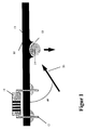
- Figure 1 is a circuit board 10 with components 11 with connecting wires 12 schematically shown, the one not shown in detail Soldering system according to one described in DE-A 44 16 788 Wave soldering processes are processed.
- the one on a transport frame Printed circuit boards 10 are arranged with a transport device in Transport direction 15 promoted to a wetting device in the Flux applied to the lower solder top of the circuit board 10 becomes.
- Cold gas jet device 16 consists essentially of a Cold gas mixer 17 with two lines 23, 24 on the input side a cold-insulated tank 21 for cryogenic liquefied gases or Gas mixtures is connected.
- An air evaporator 22 is in line 23 arranged in which the from the tank 21 to the cold gas mixer 17th Pumped cryogenic liquefied gas is evaporated.
- Between the Air evaporator 22 and the cold gas mixer is in line 23 and in the line 24 can be controlled via control lines 18, 19 Setting means 25, 26, for example metering valves, are arranged.
- Dosing valves can be in line 23 after the air evaporator existing gases and those conveyed in line 24 from tank 21 Liquid gas quantities are controlled or regulated. You can do that Cold gas mixer 17 supplied different amounts of gas and liquid gas will. Via the setting of the gas mixing ratio LPG in the cold gas mixer 17 can be any cold gas stream be generated.
- the cold gas mixer 17 is on the output side via a line 29 arranged and controllable via control line 20 setting means 27, for example a solenoid valve, is connected to distributor element 28.
- the distributor element 28, for example a distributor pipe extends over the entire width 51 of the circuit board 10 and is the carrier of Nozzles 31, 32, 39 are formed, each of which has branch lines 32, 33, 34 are supplied with the cold gas stream generated in the cold gas mixer.
- the nozzles 30, 31, 39 are designed and have Laval nozzles Laval channels 35 for converting the cold gas flow into a cold one Gas jet on.
- the distributor element 28 has means 36 for setting the angular position 37 between the printed circuit board 10 and the nozzles 30, 31, 39 on.
- the means 36 for example a swivel joint, can can of course also be assigned to the nozzles 30, 31, 39. At this configuration, the angular position 37 of each nozzle 30, 31, 39th can be set individually.
- These distributor elements 28 can be arranged parallel to each other in the transport direction.
- the distributor element and / or the cold gas mixer 17 are Temperature sensors 38, 40 assigned by means of which the actual temperature determined and a control as a control signal Can be made available.
- the example programmable logic controller 41 With the example programmable logic controller 41, the setting means 25, 26, 27 according to the operating state of the soldering system switched that a discontinuous mode of operation is possible. This is due to the often very irregular throughput on printed circuit boards 10th advantageous to minimize gas consumption.
- the discontinuous Control is generated as a function of a signal that the Passing through the circuit boards 10 is formed in the soldering system.
- the signal is advantageous when the printed circuit boards 10 enter the soldering system formed so that the temperature set in the cold gas mixer Cold gas flow depending on the lead section of the circuit board 10 until reaching those emerging from the nozzles 30, 31, 39 Gas jets and the actual temperatures determined with the sensors 38, 40 of the gas flow is set.
- the Cold gas jet device 16 is provided with two control variants different temperature setpoints operated. In the first Operating mode, the cold gas jet device 16 from the warm Condition at about 20 ° C in the actual operating state cold.
- the device 16 so driven cold with a cold gas stream for a long time until the sensors 40 and / or 38 a temperature between -60 ° C and -70 ° C is detected. Then a gas stream with a temperature between -20 ° C and -60 ° C, preferably between -25 ° C to -30 ° C and -35 ° C to -40 ° C to form the gas jets emerging from the nozzles 30, 31, 39 set.
- the cold gas mixer 17 is shown schematically in FIG. 3 in section.
- the cold gas mixer 17 essentially consists of a mixing chamber 42, the gas inlet 43 with line 23 and over Liquid gas supply 44 is connected to line 24.
- the Liquid gas supply 44 has an outlet nozzle 45 with a round one Exit channel 46, in front of which an atomizing element 47 is arranged is.
- the atomizing element 47 is designed as a baffle plate and with Distance arranged in front of the outlet channel 46.
- the baffle plate 47 runs at an angle of incidence 52> 90 ° to the outlet channel 46.
- In the mixing chamber 42 are cryogenic via the liquid gas supply 44 liquefied gas and mixed through gas inlet 43 gas such that before the cold gas outlet 48, the mass of liquid less than that of the gas is.
- the liquid gas gets through the round Exit channel 46 on the atomizing element 47, making it very fine the mixed gas chamber is sprayed and evaporated there. This will the gas supplied through the gas inlet is cooled and over Cold gas
- the circuit boards can pass through the solder wave by means of another flat jet nozzle from below with inert gas be charged.
- the training can be smaller Solder pearls reduced and regarding the procedure described above Reliability can be further increased.
Landscapes
- Engineering & Computer Science (AREA)
- Mechanical Engineering (AREA)
- Manufacturing & Machinery (AREA)
- Microelectronics & Electronic Packaging (AREA)
- Electric Connection Of Electric Components To Printed Circuits (AREA)
- Molten Solder (AREA)
- Manufacturing Of Printed Wiring (AREA)
- Cleaning In General (AREA)
Abstract
Description
Die Erfindung betrifft ein Verfahren und eine Vorrichtung zur
mechanischen Beseitigung von Lotkugeln auf der Oberfläche von
Leiterplatten nach dem Oberbegriff der Ansprüche 1 und 12 sowie einen
Kaltgasmischer zum Bereitstellen eines kalten Gasstromes für die
mechanische Beseitigung von Lotkugeln auf der Oberfläche von
Leiterplatten nach dem Oberbegriff des Anspruches 17.The invention relates to a method and an apparatus for
mechanical removal of solder balls on the surface of
Printed circuit boards according to the preamble of
Beim Wellenlöten von Leiterplatten entstehen aufgrund verschiedener physikalischer Effekte sogenannte Lotkugeln. Diese können bei elektronischen Geräten zu erheblichen Funktionsstörungen führen. Derartige Lotkugeln wurden früher durch einen Waschvorgang unter Verwendung von Fluorkohlenwasserstoffen (FCKW's) beseitigt. Da aus Umweltschutzgründen der Einsatz von FCKW nicht mehr ohne massive Einschränkungen möglich ist, werden umweltverträgliche Verfahren eingesetzt.When wave soldering circuit boards arise due to various physical effects so-called solder balls. These can be found at electronic devices lead to considerable malfunctions. Such solder balls were previously underwashed Removed the use of fluorocarbons (CFCs). From there For environmental reasons, the use of CFCs is no longer without massive Restrictions are possible, environmentally friendly procedures used.
Man versucht daher, durch die Verwendung modifizierter Lötstoplacke mit abhäsiven Eigenschaften die Ausbildung von Lotkugeln von vorn herein zu verhindern. Weil der Lötstoplack aber auch adhäsiv auf den Leiterbahnen haften muß, kann die Adhäsion von Lot auf diese Weise nicht vollständig verhindert werden.One tries, therefore, by using modified solder resist with abhesive properties, the formation of solder balls from the front to prevent in. Because the solder resist also adheres to the Conductors must adhere, the adhesion of solder in this way cannot be completely prevented.
Es wurde daher in der DE-A 44 16 788 bereits vorgeschlagen, durch eine zusätzliche künstliche Abkühlung mit einem Gasstrom die Haftung von Lotkügelchen auf der Oberfläche der Leiterplatten zu verhindern. Dabei soll durch einen höchstens Raumtemperatur aufweisenden Gasstrom eine thermomechanische Fehlanpassung zwischen Lötstopmaske und Lot erzeugt werden, damit ein Anhaften der Lotkügelchen erst gar nicht stattfinden kann.It has therefore already been proposed in DE-A 44 16 788 by an additional artificial cooling with a gas stream the liability to prevent solder balls on the surface of the circuit boards. It should be at room temperature Gas flow a thermomechanical mismatch between Solder mask and solder are generated to ensure that the Solder balls cannot take place at all.
Neben diesen Maßnahmen zur Vermeidung von anhaftenden Lotkugeln auf der Oberfläche der Leiterplatten sind Bürsteinrichtungen bekannt, mittels denen die Lotkugeln mechanisch beseitigt werden. Es kann dabei aber nicht ausgeschlossen werden, daß auf der Oberfläche der Leiterplatte vorhandene SMD-Bauteile (Surface Mounted Devices), sowie Bauteile mit Anschlußdrähten oder die Leiterplatte als ganzes beschädigt werden.In addition to these measures to avoid adhering solder balls brushing devices are known on the surface of the printed circuit boards, by means of which the solder balls are mechanically removed. It can but it cannot be excluded that on the surface of the PCB existing SMD components (Surface Mounted Devices), as well as components with connecting wires or the printed circuit board as a whole to be damaged.
Der Erfindung liegt die Aufgabe zugrunde, ein Verfahren und eine Vorrichtung zur mechanischen Beseitigung von Lotkugeln auf der Oberfläche von Leiterplatten zu schaffen, mit dem sich anhaftende Lotkugeln ohne Beschädigung der Leiterplatten entfernen lassen.The invention is based, a method and a task Device for the mechanical removal of solder balls on the To create surface of printed circuit boards with which adhering Have the solder balls removed without damaging the circuit boards.
Ausgehend von dem im Oberbegriff genannten Stand der Technik ist
diese Aufgabe erfindungsgemäß gelöst, mit den in den Ansprüchen 1
und 12 angegebenen Merkmalen.Starting from the prior art mentioned in the preamble
solved this problem according to the invention with the in
Weiterbildungen der Erfindung sind in den Unteransprüchen angegeben. Further developments of the invention are in the subclaims specified.
Bei dem erfindungsgemäßen Verfahren wird die mechanische Beseitigung der Lotkugeln während der Zerstörung der zwischen Lötstoplack und Lot gebildeten Adhäsionsflächen durchgeführt; dabei erfolgt die Abkühlung der Oberfläche der Leiterplatten und die mechanische Beseitigung der Lotkugeln durch einen kalten Gasstrahl gleichzeitig. Durch die Formung eines kalten Gasstrahles wird an der Oberfläche der Leiterplatte ein hoher Abblasedruck gebildet, der die Lotkugeln von der Oberfläche der Leiterplatten entfernt.In the method according to the invention, the mechanical Eliminate the solder balls while destroying the between Solder resist and solder formed adhesion surfaces performed; there the surface of the circuit boards is cooled and the mechanical removal of the solder balls by a cold gas jet at the same time. By forming a cold gas jet on the Surface of the circuit board a high blow-off pressure is formed, which the Solder balls removed from the surface of the circuit boards.
Eine besonders gute mechanische Beseitigung der Lotkugeln läßt sich mit dem erfindungsgemäßen Verfahren dann erzielen, wenn der Gasstrahl mit einer Temperatur zwischen -20 °C und -60 °C unter einem Anblaswinkel < 45°, vorzugsweise unter einem Anblaswinkel zwischen 30° und 40°, gemessen zwischen der Leiterplatte und der Austrittsöffnung der Düse, die Oberfläche der Leiterplatten beaufschlagt. Durch die Einstell- und Temperaturparameter läßt sich eine nahezu vollständige Entfernung der Lotkugeln sicherstellen.A particularly good mechanical removal of the solder balls can be achieve with the inventive method when the gas jet with a temperature between -20 ° C and -60 ° C below one Blow angle <45 °, preferably at a blow angle between 30 ° and 40 °, measured between the circuit board and the Outlet opening of the nozzle, the surface of the circuit boards acted upon. Through the setting and temperature parameters ensure an almost complete removal of the solder balls.
Besonders gute Arbeitsergebnisse lassen sich dann erzielen, wenn die Lotkugeln nach dem Erstarren von dem Gasstrahl beaufschlagt werden. Unter Erstarren wird hierbei eine Abkühlung der Lotkugeln bis zu einer nicht mehr flüssigen Konsistenz verstanden. Durch die mechanische Beseitigung der Lotkugeln nach dem Erstarren wird ein Versprühen durch den mit hohem Abblasedruck auftreffenden kalten Gasstrahl vermieden.Particularly good work results can be achieved if the Solder balls are impacted by the gas jet after solidification. Under solidification, the solder balls are cooled down to one no longer understood liquid consistency. By mechanical Removing the solder balls after solidification becomes a spray due to the cold gas jet hitting with high blow-off pressure avoided.
Bevorzugt wird mindestens eine Seite der Oberfläche der Leiterplatte über die gesamte Breite mit vielen kalten Gasstrahlen beaufschlagt, die durch Vereinzelung aus einem kalten Gasstrom jeweils erzeugt werden. Dabei wird die Oberfläche der Leiterplatten vorzugsweise in der Förderrichtung der Leiterplatten über die gesamte Breite mit einer angepaßten Anzahl von Gasstrahlen beaufschlagt. Durch die in Förderrichtung der Leiterplatten aus Düsen austretenden Gasstrahlen kann auf eine Bewegung der Düsen verzichtet werden. Es ist selbstverständlich auch möglich, die Düsen seitlich zum Förderweg der Leiterplatten anzuordnen und die Düsen senkrecht zum Förderweg der Leiterplatten zu verfahren. Durch die Anordnung mehrerer in Förderrichtung der Leiterplatten hintereinander angeordnete Düsenreihen lassen sich über die gesamte Breite einer Seite der Oberfläche der Leiterplatten vorhangartige Gasstrahlenreihen ausbilden, die je nach Kältebedarf für die thermomechanische Fehlanpassung und die mechanische Entfernung der Lotkugeln zu- und abgeschaltet werden.At least one side of the surface of the printed circuit board is preferred across the entire width exposed to many cold gas jets that can be generated by separation from a cold gas stream. The surface of the circuit boards is preferably in the Direction of conveyance of the printed circuit boards over the entire width with a adjusted number of gas jets. By in Direction of conveyance of the printed circuit boards from gas jets there is no need to move the nozzles. It is of course also possible, the nozzles to the side of the conveying path Arrange circuit boards and the nozzles perpendicular to the conveying path of the PCBs to move. By arranging several in Direction of conveyance of the printed circuit boards arranged one behind the other Rows of nozzles can be spread over the entire width of one side of the Surface of the circuit board curtain-like rows of gas jets train, depending on the cooling requirements for the thermomechanical Mismatch and the mechanical removal of the solder balls too be switched off.
Besonders vorteilhaft wird der für die Ausbildung der Gasstrahlen erzeugte kalte Gasstrom aus einem Inertgas gebildet, wodurch die Oxidation der Lötstellen behindert und die Oberflächenspannung des Lotes erhöht wird. Als Inertgas werden Stickstoff, Argon, Kohlendioxid oder Gasmischungen daraus eingesetzt. Die Temperatur des kalten Gas-stromes wird aus der gasförmigen und flüssigen Phase des eingesetzten Gases oder Gasgemisches gebildet. Die Mischung des tiefkalt verflüssigten und gasförmigen Gases oder Gasgemisches erfolgt so, daß vor der Mischung die Masse der Flüssigkeit geringer als die des Gases ist. Durch die erfindungsgemäße Bildung eines kalten Gasstromes durch Vermischen der gasförmigen und flüssigen Phase des eingesetzten Gases oder Gasgemisches kann vorteilhaft mit geringem Aufwand ein begrenzter Bereich der Oberfläche der Leiterplatten mit einem Gasstrahl beaufschlagt werden, der auf Temperaturen zwischen -20 °C und -60 °C abgekühlt ist.This is particularly advantageous for the formation of the gas jets generated cold gas stream formed from an inert gas, causing the Oxidation of the solder joints hindered and the surface tension of the Lotes is increased. Nitrogen, argon and carbon dioxide are used as inert gases or gas mixtures used. The temperature of the cold Gas flow is made up of the gaseous and liquid phases of the used gas or gas mixture formed. The mix of cryogenic liquefied and gaseous gas or gas mixture so that before the mixture the mass of the liquid is less than that of the Is gas. The inventive formation of a cold Gas flow by mixing the gaseous and liquid phases of the gas or gas mixture used can advantageously with limited area of the surface of the Printed circuit boards are subjected to a gas jet that is on Temperatures between -20 ° C and -60 ° C has cooled.
Durch die Formung des Gasstromes zu Gasstrahlen in Lavalkanälen der Düsen werden hohe Austrittsgeschwindigkeiten aus den Düsen erzielt, mittels denen sich ein hoher Abblasedruck bei geringem Gasdurchsatz an der Oberfläche der Leiterbahnen erreichen läßt. By shaping the gas flow into gas jets in the Laval channels Nozzles achieve high exit speeds from the nozzles, by means of which there is a high blow-off pressure with low gas throughput can be reached on the surface of the conductor tracks.
Besonders gute wirtschaftliche Ergebnisse lassen sich mit dem erfindungsgemäßen Verfahren dann erzielen, wenn der kalte Gasstrom diskontinuierlich in Abhängigkeit von einem Signal erzeugt wird, daß beim Durchlaufen der Leiterplatten in der Lötanlage gebildet wird. Das Signal kann hierbei zum Beispiel beim Eintritt der Leiterplatten in die Lötanlage erzeugt werden; es kann jedoch auch an einer anderen Stelle der Lötanlage gebildet und zum Starten der Gasstrahlen verwendet werden. Um den bevorzugten Temperaturbereich zwischen -20 °C und -60 °C vorzugsweise -25 °C bis -45 °C an der Oberfläche der Leiterplatten zu erzielen wird die Temperatur des kalten Gasstromes in Abhängigkeit von der Vorlaufstrecke der Leiterplatte bis zum Erreichen der Gasstrahlen und/oder der Ist-Temperatur des Gasstromes eingestellt. Dabei wird die Abkühlung in mehreren Phasen mit unterschiedlichen Temperaturwerten durchgeführt. Die Vorrichtung zur mechanischen Beseitigung von Lötkugeln wird nach einem Steuerzyklus kalt gefahren und nach einem anderen Steuerzyklus wird die Temperatur der Leiterplatte und des Gasstromes zum Beaufschlagungszeitpunkt mittels der Gas-strahlen berücksichtigt.Particularly good economic results can be achieved with the Achieve method according to the invention when the cold gas stream is generated discontinuously depending on a signal that is formed when passing through the circuit boards in the soldering system. The Signal can be, for example, when the circuit boards enter the Soldering system are generated; however, it can be in another location the soldering system and used to start the gas jets will. Around the preferred temperature range between -20 ° C and -60 ° C preferably -25 ° C to -45 ° C on the surface of the PCB temperature will be the temperature of the cold gas flow in Depends on the lead distance of the PCB until it is reached the gas jets and / or the actual temperature of the gas stream set. The cooling is carried out in several phases different temperature values. The device for Mechanical removal of solder balls is done after a control cycle driven cold and after another control cycle the PCB and gas flow temperature to The time of exposure to the gas jets is taken into account.
Durch eine Vorrichtung gemäß dem Anspruch 12 lassen sich in
einfacher Weise kalte Gasstrahlen erzeugen und auf die Oberfläche der
Leiterplatten richten. Durch die Ausbildung der Düse als Lavaldüse
lassen sich hohe Abblasedrücke für die mechanische Entfernung der
Lotkugeln erzeugen.By a device according to
Durch die Merkmale der Ansprüche 18, 19 und 20 läßt sich mit
geringem Aufwand ein kalter Gasstrom erzeugen, dessen Temperatur in
einfacher Weise an die Lötbedingungen und die Lötanlagen angepaßt
werden kann.The features of
Ein Ausführungsbeispiel der Erfindung ist in der Zeichnung dargestellt und wird im folgenden näher beschrieben. An embodiment of the invention is shown in the drawing and is described in more detail below.
Es zeigen
- Figur 1
- eine schematische Seitenansicht eines Ausschnittes einer Leiterplatte;
- Figur 2
- eine schematische Darstellung der Vorrichtung zum Erzeugen von kalten Gasstrahlen;
- Figur 3
- eine schematische Darstellung des in Figur 2 dargestellten Kaltgasmischers im Schnitt.
- Figure 1
- is a schematic side view of a section of a circuit board;
- Figure 2
- a schematic representation of the device for generating cold gas jets;
- Figure 3
- a schematic representation of the cold gas mixer shown in Figure 2 in section.
In Figur 1 ist eine Leiterplatte 10 mit Bauteilen 11 mit Anschlußdrähten
12 schematisch dargestellt, die in einer nicht näher dargestellten
Lötanlage nach einem in der DE-A 44 16 788 beschriebenen
Wellenlötverfahren bearbeitet werden. Die auf einem Transportrahmen
angeordneten Leiterplatten 10 werden mit einer Transporteinrichtung in
Transportrichtung 15 zu einer Benetzungseinrichtung gefördert, in der
Flußmittel auf die untere Lötoberseite der Leiterplatte 10 aufgebracht
wird.In Figure 1 is a
Nachdem der Transportrahmen mit der zu lötenden Leiterplatte 10 über
die Benetzungseinrichtung hinweggelaufen ist, gelangt er in den
Bereich einer Wellenlöteinrichtung. Dabei ist die Transporteinrichtung
bezüglich der Lotwelle so ausgerichtet, daß die zu lötende Leiterplatte
10 die Lotwelle durchläuft, wodurch das Löten erfolgt. Beim Löten wird
die Lotwelle in ihrem Strömungsverhalten durch die Bauteile bzw. die
Anschlußdrähte 12 gestört. Dies führt zum Separieren des Lotes, das in
der Lötatmosphäre eine Zinn-Blei-Mischoxidoberfläche ausbildet. Diese
oxidierten Lötvolumina werden auf dem Lötstoplack 13 der Leiterplatten
10 als Lotkügelchen 14 adhäsiv fixiert. In Transportrichtung 15 der
Leiterplatte 10 ist hinter der Lötvorrichtung eine Kaltgasstrahleinrichtung
16 zur mechanischen Beseitigung der Lotkugeln 14 vorgesehen. Die in
den Figuren 2 und 3 nur schematisch dargestellte
Kaltgasstrahleinrichtung 16 besteht im wesentlichen aus einem
Kaltgasmischer 17 der eingangsseitig über zwei Leitungen 23, 24 mit
einem kälteisolierten Tank 21 für tiefkalt verflüssigte Gase oder
Gasgemische verbunden ist. In der Leitung 23 ist ein Luftverdampfer 22
angeordnet, in dem das aus dem Tank 21 zum Kaltgasmischer 17
geförderte tiefkalt verflüssigte Gas verdampft wird. Zwischen dem
Luftverdampfer 22 und dem Kaltgasmischer ist in der Leitung 23 und in
der Leitung 24 ein über Steuerleitungen 18, 19 ansteuerbare
Einstellmittel 25, 26, beispielsweise Dosierventile, angeordnet. Über die
Dosierventile können die in Leitung 23 nach dem Luftverdampfer
vorhandenen Gase und die in Leitung 24 vom Tank 21 geförderten
Flüssiggasmengen gesteuert oder geregelt werden. Dabei können dem
Kaltgasmischer 17 differierende Gas- und Flüssiggasmengen zugeführt
werden. Über die Einstellung des Mischungsverhältnisses Gas zu
Flüssiggas in dem Kaltgasmischer 17 kann ein beliebig kalter Gasstrom
erzeugt werden.After the transport frame with the
Selbstverständlich kann die Einstellung der Gas- und Flüssiggasmengen auch über zu- und abschaltbare Bypassleitungen mit unterschiedlichen Durchsatzvolumen und dergleichen erfolgen.Of course, the adjustment of the gas and Liquefied petroleum gas quantities also via bypass lines that can be switched on and off different throughput volumes and the like.
Ausgangsseitig ist der Kaltgasmischer 17 über ein in Leitung 29
angeordnetes und über Steuerleitung 20 ansteuerbares Einstellmittel
27, beispielsweise ein Magnetventil, mit Verteilerelement 28 verbunden.
Das Verteilerelement 28, beispielsweise ein Verteilerrohr, erstreckt sich
über die gesamte Breite 51 der Leiterplatte 10 und ist als Träger der
Düsen 31, 32, 39 ausgebildet, die jeweils über Abzweigleitungen 32, 33,
34 mit dem im Kaltgasmischer erzeugten Kaltgasstrom versorgt werden.
Die Düsen 30, 31, 39 sind als Lavaldüsen ausgebildet und weisen
Laval-kanäle 35 zur Umformung des Kaltgasstromes in einen kalten
Gasstrahl auf. Das Verteilerelement 28 weist Mittel 36 zum Einstellen
der Winkellage 37 zwischen Leiterplatte 10 und der Düsen 30, 31, 39
auf. Die Mittel 36, beispielsweise ein Drehgelenk, können
selbstverständlich auch den Düsen 30, 31, 39 zugeordnet sein. Bei
dieser Ausbildung kann die Winkellage 37 von jeder Düse 30, 31, 39
individuell eingestellt werden. Mehrere dieser Verteilerelemente 28
können in Transportrichtung parallel zueinander angeordnet werden.
Dem Verteilerelement und/oder dem Kaltgasmischer 17 sind
Temperatursensoren 38, 40 zugeordnet mittels denen die Ist-Temperatur
ermittelt und einer Steuerung als Steuersignal zur
Verfügung gestellt werden kann. Mit der beispielsweise
speicherprogrammierbaren Steuerung 41 werden die Einstellmittel 25,
26, 27 entsprechend des Betriebszustandes der Lötanlage so
geschaltet, daß eine diskontinuierliche Betriebsweise möglich ist. Dies
ist wegen des oft sehr unregelmäßigen Durchsatzes an Leiterplatten 10
vorteilhaft um den Gasverbrauch zu minimieren. Die diskontinuierliche
Steuerung wird in Abhängigkeit von einem Signal erzeugt, das beim
Durchlaufen der Leiterplatten 10 in der Lötanlage gebildet wird.
Vorteilhaft wird das Signal beim Eintritt der Leiterplatten 10 in Lötanlage
gebildet, so daß die im Kaltgasmischer eingestellte Temperatur des
Kaltgasstromes in Abhängigkeit von der Vorlaufstrecke der Leiterplatte
10 bis zum Erreichen der aus den Düsen 30, 31, 39 austretenden
Gasstrahlen und der mit den Sensoren 38, 40 ermittelten Ist-Temperaturen
des Gasstromes eingestellt wird. Die
Kaltgasstrahleinrichtung 16 wird mit zwei Steuervarianten mit
unterschiedlichen Temperatur-Sollwerten betrieben. In der ersten
Betriebsweise wird die Kaltgasstrahleinrichtung 16 aus dem warmen
Zustand bei ca. 20 °C in den eigentlichen Betriebszustand kaltgefahren.
Bei einer Temperatur > -20 °C bis -30 °C wird die Einrichtung 16 so
lange mit einem kalten Gasstrom kalt gefahren bis über die Sensoren 40
und/oder 38 eine Temperatur zwischen -60 °C und -70 °C erfaßt wird.
Danach wird ein Gasstrom mit einer Temperatur zwischen -20 °C und
-60 °C vorzugsweise zwischen -25 °C bis -30 °C und -35 °C bis -40 °C
zur Bildung der aus der Düsen 30, 31, 39 austretenden Gasstrahlen
eingestellt. The
Der Kaltgasmischer 17 ist in Figur 3 schematisch im Schnitt dargestellt.
Der Kaltgasmischer 17 besteht im wesentlichen aus einer Mischkammer
42, die über Gaseingang 43 mit Leitung 23 und über
Flüssiggaszuführung 44 mit Leitung 24 verbunden ist. Die
Flüssiggaszuführung 44 weist eine Austrittsdüse 45 mit einem runden
Austrittskanal 46 auf, vor dem ein Verdüsungselement 47 angeordnet
ist. Das Verdüsungselement 47 ist als Prallplatte ausgebildet und mit
Abstand vor dem Austrittskanal 46 angeordnet. Die Prallplatte 47
verläuft unter einem Auftreffwinkel 52 > 90° zu dem Austrittskanal 46. In
der Mischkammer 42 werden über Flüssiggaszuführung 44 tiefkalt
verflüssigtes Gas und über Gaseingang 43 Gas derartig vermischt, daß
vor dem Kaltgasausgang 48 die Masse an Flüssigkeit geringer als die
des Gases ist. Dazu gelangt das Flüssiggas durch den runden
Austrittskanal 46 auf das Verdüsungselement 47, wodurch es feinst in
der Mischgaskammer versprüht wird und dort verdampft. Dadurch wird
das über Gaseingang zugeführte Gas abgekühlt und über
Kaltgasausgang zu dem Verteilerelement 28 geführt.The
Versuche haben ergeben, daß ein mit einer Temperatur zwischen
-20 °C und -60 °C in den Lavalkanälen 35 geformter Gasstrahl 50 aus
einem Inertgas oder einer Inertgasmischung, der unter einem
Anblasewinkel 49° von < 45°, vorzugsweise unter einem Anblasewinkel
zwischen 30° und 40°, auf die nicht mehr flüssige Lotkugel 14 trifft, eine
Fehlanpassung 53 zwischen Lötstoplack 13 und Lotkugel 14 bei
gleichzeitiger mechanischer Entfernung der Lotkugeln 14 erzeugt.
Durch die Erfindung werden die Lotkugeln 14 bei der
Entspannungskontraktion mechanisch durch den Gasstrahl 50 entfernt.Experiments have shown that a temperature between
-20 ° C and -60 ° C in the
Optional können die Leiterplatten beim Durchgang durch die Lotwelle mittels einer weiteren Flachstrahldüse von unten mit Inertgas beaufschlagt werden. Auf diese Weise kann die Ausbildung kleiner Lotperlen reduziert und das oben beschriebene Verfahren hinsichtlich Zuverlässigkeit weiter gesteigert werden.Optionally, the circuit boards can pass through the solder wave by means of another flat jet nozzle from below with inert gas be charged. In this way, the training can be smaller Solder pearls reduced and regarding the procedure described above Reliability can be further increased.
Claims (20)
dadurch gekennzeichnet,
daß die Lotkugeln (14) durch mindestens einen auf die Oberfläche gerichteten kalten Gasstrahl (50) mechanisch beseitigt werden.Process for the mechanical removal of solder balls on the surface of printed circuit boards immediately after passing through the solder wave when wave soldering printed circuit boards in a soldering system
characterized,
that the solder balls (14) are mechanically removed by at least one cold gas jet (50) directed onto the surface.
dadurch gekennzeichnet,
daß die Oberfläche von dem Gasstrahl (50) mit einer Temperatur zwischen -20 °C und -60 °C beaufschlagt wird.Method according to claim 1,
characterized,
that the surface of the gas jet (50) is subjected to a temperature between -20 ° C and -60 ° C.
dadurch gekennzeichnet,
daß die Oberfläche nach dem Erstarren der Lotkugeln (14) von dem Gasstrahl (50) beaufschlagt wird.The method of claim 1 or 2,
characterized,
that the surface is acted upon by the gas jet (50) after the solidification of the solder balls (14).
dadurch gekennzeichnet,
daß der Gasstrahl (50) unter einem Anblasewinkel (49) kleiner 45°, vorzugsweise unter einem Anblasewinkel zwischen 30° und 40°, die Oberfläche beaufschlagt.Method according to one of claims 1 to 3,
characterized,
that the gas jet (50) acts on the surface at a blowing angle (49) of less than 45 °, preferably at a blowing angle between 30 ° and 40 °.
dadurch gekennzeichnet,
daß mindestens eine Seite der Oberfläche über die gesamte Breite (51) der Leiterplatte (10) mit mehreren kalten Gasstrahlen (50) beaufschlagt wird, die durch eine Vereinzelung aus einem kalten Gasstom jeweils erzeugt werdenMethod according to one of claims 1 to 4,
characterized,
that at least one side of the surface over the entire width (51) of the printed circuit board (10) is acted upon by a plurality of cold gas jets (50), each of which is generated by a separation from a cold gas stream
dadurch gekennzeichnet
daß der kalte Gasstrom aus einem Inertgas, insbesondere Stickstoff, Argon, Kohlendioxid oder Gasmischungen daraus, gebildet wird.Method according to one of claims 1 to 5,
characterized
that the cold gas stream is formed from an inert gas, in particular nitrogen, argon, carbon dioxide or gas mixtures thereof.
dadurch gekennzeichnet,
daß der kalte Gasstrom aus der gasförmigen und flüssigen Phase des eingesetzten Gases oder Gasgemisches gebildet wird.Method according to one of claims 1 to 6,
characterized,
that the cold gas stream is formed from the gaseous and liquid phase of the gas or gas mixture used.
dadurch gekennzeichnet,
daß die kalten Gasstrahlen (50) in Düsen (30, 31, 39) gebildet und mit einem hohen Abblasedruck gegen die Oberfläche gerichtet werden.Method according to one of claims 1 to 7,
characterized,
that the cold gas jets (50) are formed in nozzles (30, 31, 39) and directed against the surface with a high blow-off pressure.
dadurch gekennzeichnet,
daß die Gasstrahlen (50) in Lavalkanälen (35) der Düsen (30, 31, 39) geformt werden.Method according to one of claims 1 to 8,
characterized,
that the gas jets (50) in Laval channels (35) of the nozzles (30, 31, 39) are formed.
dadurch gekennzeichnet,
daß der kalte Gasstrom diskontinuierlich in Abhänigkeit von einem Signal erzeugt wird, das beim Durchlaufen der Leiterplatten (10) in der Lötanlage gebildet wird. Method according to one of claims 1 to 9,
characterized,
that the cold gas flow is generated intermittently as a function of a signal which is formed in the soldering system when passing through the printed circuit boards (10).
dadurch gekennzeichnet,
daß die Temperatur des kalten Gasstroms in Abhängigkeit von der Vorlaufstrecke der Leiterplatte (10) bis zum Erreichen der Gasstrahlen (50) und/oder der Ist-Temperatur (38, 40) des Gasstroms eingestellt wird.Method according to one of claims 1 to 10,
characterized,
that the temperature of the cold gas flow is set depending on the lead of the circuit board (10) until the gas jets (50) and / or the actual temperature (38, 40) of the gas flow is reached.
gekennzeichnet durch,
einen Kaltgasmischer (17) der eingangseitig über zwei Leitungen (23, 24) mit mindestens einem Tank (21) für tiefkalt verflüssigte Gase oder Gasgemische und ausgangsseitig mit mindestens einer auf die Oberfläche der Leiterplatten (10) gerichteten Düse (30, 31, 39) verbunden ist.Device for mechanical removal of solder balls on the surface of printed circuit boards immediately after passing through the solder wave when soldering printed circuit boards in a soldering system,
marked by,
a cold gas mixer (17) which has two lines (23, 24) on the inlet side with at least one tank (21) for cryogenic liquefied gases or gas mixtures and on the outlet side with at least one nozzle (30, 31, 39) directed towards the surface of the printed circuit boards (10) connected is.
dadurch gekennzeichnet,
daß die Düse (30, 31, 39) als Lavaldüse ausgebildet ist.Device according to claim 12,
characterized,
that the nozzle (30, 31, 39) is designed as a Laval nozzle.
dadurch gekennzeichnet,
daß in einer Leitung (23) ein Verdampfer (22) angeordnet ist.Device according to claim 12 or 13,
characterized,
that an evaporator (22) is arranged in a line (23).
dadurch gekennzeichnet,
daß in den Leitungen (23, 24) ansteuerbare Einstellmittel (25, 26) angeordnet sind. Device according to one of claims 12 to 15,
characterized,
that controllable setting means (25, 26) are arranged in the lines (23, 24).
dadurch gekennzeichnet,
daß zwischen den Düsen (30, 31, 39) und dem Kaltgasmischer (17) ein Verteilerelement (28) mit vorgeschaltetem Einstellmittel (27) angeordnet ist, das als Düsenträger ausgebildet ist.Device according to one of claims 12 to 15,
characterized,
that between the nozzles (30, 31, 39) and the cold gas mixer (17) a distributor element (28) with an upstream adjusting means (27) is arranged, which is designed as a nozzle holder.
dadurch gekennzeichnet,
daß das Verteilerelement (28) und/oder die Düsen (30, 31, 39) über Mittel (36) in ihrer Winkellage (37) zur Oberfläche einstellbar sind.Device according to one of claims 12 to 16,
characterized,
that the distributor element (28) and / or the nozzles (30, 31, 39) can be adjusted in their angular position (37) to the surface by means (36).
dadurch gekennzeichnet,
daß der Kaltgasmischer (17) aus einer Mischkammer (45) mit einem Gaseingang (43) und einem Kaltgasausgang (48) und einer in die Mischkammer (45) geführte Flüssiggaszuführung (44) besteht, die eine Austrittsdüse (45) mit einem Austrittskanal (46) aufweist, dem ein Verdüsungselement (47) zugeordnet ist.Device according to one of claims 1 to 17,
characterized,
that the cold gas mixer (17) consists of a mixing chamber (45) with a gas inlet (43) and a cold gas outlet (48) and a liquid gas feed (44) guided into the mixing chamber (45), which has an outlet nozzle (45) with an outlet channel (46 ), to which a spraying element (47) is assigned.
dadurch gekennzeichnet,
daß der Austrittskanal (46) rund ist und das Verdüsungselement (47) als Prallplatte ausgebildet ist und mit Abstand vor dem Austrittskanal (46) angeordnet ist.Device according to claim 18,
characterized,
that the outlet channel (46) is round and the atomizing element (47) is designed as a baffle plate and is arranged at a distance in front of the outlet channel (46).
dadurch gekennzeichnet,
daß die Prallplatte unter einem Auftreffwinkel (52) größer 90° zu dem Austrittskanal (46) verläuft.Device according to claim 18 or 19,
characterized,
that the baffle plate extends at an angle of incidence (52) greater than 90 ° to the outlet channel (46).
Applications Claiming Priority (2)
| Application Number | Priority Date | Filing Date | Title |
|---|---|---|---|
| DE19632335 | 1996-08-10 | ||
| DE19632335A DE19632335C2 (en) | 1996-08-10 | 1996-08-10 | Method and device for mechanically removing solder balls on the surface of printed circuit boards |
Publications (1)
| Publication Number | Publication Date |
|---|---|
| EP0824051A1 true EP0824051A1 (en) | 1998-02-18 |
Family
ID=7802332
Family Applications (1)
| Application Number | Title | Priority Date | Filing Date |
|---|---|---|---|
| EP97111992A Withdrawn EP0824051A1 (en) | 1996-08-10 | 1997-07-15 | Process and device to mechanically remove solder balls from the surface of printed circuit boards |
Country Status (8)
| Country | Link |
|---|---|
| US (1) | US5911355A (en) |
| EP (1) | EP0824051A1 (en) |
| KR (1) | KR19980018549A (en) |
| DE (1) | DE19632335C2 (en) |
| ID (1) | ID18411A (en) |
| SG (1) | SG67400A1 (en) |
| TW (1) | TW363006B (en) |
| ZA (1) | ZA976081B (en) |
Families Citing this family (2)
| Publication number | Priority date | Publication date | Assignee | Title |
|---|---|---|---|---|
| US6216938B1 (en) * | 1999-09-30 | 2001-04-17 | International Business Machines Corporation | Machine and process for reworking circuit boards |
| DE102004003521B3 (en) * | 2004-01-21 | 2005-02-17 | Siemens Ag | Repair soldering head for component replacement with circulation of heat transfer medium used for melting solder for releasing component to be replaced |
Citations (6)
| Publication number | Priority date | Publication date | Assignee | Title |
|---|---|---|---|---|
| DE3843191C1 (en) * | 1988-12-22 | 1990-03-22 | Bts Broadcast Television Systems Gmbh, 6100 Darmstadt, De | Device for soldering |
| JPH066025A (en) * | 1992-06-24 | 1994-01-14 | Fujitsu Ltd | Solder ball removing method |
| JPH0671467A (en) * | 1992-08-21 | 1994-03-15 | Fujitsu Ltd | Method and device for cleaning printed board by using laser beam |
| DE4416788A1 (en) * | 1994-05-06 | 1995-11-09 | Siemens Ag | Process for wave soldering of printed circuit boards |
| EP0761361A1 (en) * | 1995-09-08 | 1997-03-12 | Ford Motor Company | Apparatus for cooling printed circuit boards in wave soldering |
| JPH09181436A (en) * | 1995-12-22 | 1997-07-11 | Taisei Kaken:Kk | Soldering method and soldering iron |
Family Cites Families (6)
| Publication number | Priority date | Publication date | Assignee | Title |
|---|---|---|---|---|
| US3680199A (en) * | 1970-07-06 | 1972-08-01 | Texas Instruments Inc | Alloying method |
| US4419566A (en) * | 1981-05-18 | 1983-12-06 | Fortune William S | Hot air soldering and resoldering system |
| US5205461A (en) * | 1988-07-29 | 1993-04-27 | International Business Machines Corporation | Method and apparatus for fluxless solder bonding |
| US4995411A (en) * | 1988-10-07 | 1991-02-26 | Hollis Automation, Inc. | Mass soldering system providing an improved fluid blast |
| DE9304784U1 (en) * | 1993-03-29 | 1993-08-05 | Cooper Tools Gmbh, 74354 Besigheim, De | |
| US5419481A (en) * | 1993-09-21 | 1995-05-30 | Air-Vac Engineering Company, Inc. | Process and apparatus for attaching/deataching land grid array components |
-
1996
- 1996-08-10 DE DE19632335A patent/DE19632335C2/en not_active Expired - Fee Related
-
1997
- 1997-07-08 ZA ZA9706081A patent/ZA976081B/en unknown
- 1997-07-08 TW TW086109595A patent/TW363006B/en active
- 1997-07-15 SG SG1997002382A patent/SG67400A1/en unknown
- 1997-07-15 EP EP97111992A patent/EP0824051A1/en not_active Withdrawn
- 1997-07-25 US US08/900,804 patent/US5911355A/en not_active Expired - Fee Related
- 1997-08-04 ID IDP972693A patent/ID18411A/en unknown
- 1997-08-09 KR KR1019970038077A patent/KR19980018549A/en active IP Right Grant
Patent Citations (6)
| Publication number | Priority date | Publication date | Assignee | Title |
|---|---|---|---|---|
| DE3843191C1 (en) * | 1988-12-22 | 1990-03-22 | Bts Broadcast Television Systems Gmbh, 6100 Darmstadt, De | Device for soldering |
| JPH066025A (en) * | 1992-06-24 | 1994-01-14 | Fujitsu Ltd | Solder ball removing method |
| JPH0671467A (en) * | 1992-08-21 | 1994-03-15 | Fujitsu Ltd | Method and device for cleaning printed board by using laser beam |
| DE4416788A1 (en) * | 1994-05-06 | 1995-11-09 | Siemens Ag | Process for wave soldering of printed circuit boards |
| EP0761361A1 (en) * | 1995-09-08 | 1997-03-12 | Ford Motor Company | Apparatus for cooling printed circuit boards in wave soldering |
| JPH09181436A (en) * | 1995-12-22 | 1997-07-11 | Taisei Kaken:Kk | Soldering method and soldering iron |
Non-Patent Citations (3)
| Title |
|---|
| DATABASE WPI Week 9738, Derwent World Patents Index; AN 97-408897, XP002045688 * |
| PATENT ABSTRACTS OF JAPAN vol. 18, no. 202 (E - 1535) 8 April 1994 (1994-04-08) * |
| PATENT ABSTRACTS OF JAPAN vol. 18, no. 314 (M - 1621) 15 June 1994 (1994-06-15) * |
Also Published As
| Publication number | Publication date |
|---|---|
| ZA976081B (en) | 1998-02-02 |
| DE19632335A1 (en) | 1998-02-12 |
| KR19980018549A (en) | 1998-06-05 |
| TW363006B (en) | 1999-07-01 |
| SG67400A1 (en) | 1999-09-21 |
| US5911355A (en) | 1999-06-15 |
| DE19632335C2 (en) | 1999-01-21 |
| ID18411A (en) | 1998-04-09 |
Similar Documents
| Publication | Publication Date | Title |
|---|---|---|
| EP0343103B1 (en) | Method and apparatus for cooling an object | |
| DE3728557C2 (en) | ||
| EP0624391B1 (en) | Process and device for the denitrification of flue gases | |
| EP1169145B1 (en) | Method and device for cleaning substrates | |
| DE3028325A1 (en) | METHOD AND DEVICE FOR CLEANING A WORKPIECE COMPRISING A PRINTED CIRCUIT BOARD | |
| DE19632335C2 (en) | Method and device for mechanically removing solder balls on the surface of printed circuit boards | |
| WO2006005377A1 (en) | Method and device for generating dry ice particles | |
| WO2017017215A1 (en) | Method and device for coating a surface | |
| CH662290A5 (en) | NOZZLE FOR SPRAYING VISCOSE LIQUIDS. | |
| DE2852132A1 (en) | METHOD AND DEVICE FOR BULK SOLDERING OF PRINTED CIRCUIT BOARDS EQUIPPED WITH COMPONENTS | |
| DE4219913A1 (en) | Protective gas soldering installation - has special soldering chamber with circular flow of protective gas | |
| EP1972405B1 (en) | Device and method for pretreating electronic components before soldering | |
| DE2021310C3 (en) | Blowgun for removing material | |
| DE3706781C2 (en) | Method and device for camouflaging against view and for reducing the infrared radiation of watercraft | |
| EP0758282B1 (en) | Process for wave-soldering printed circuit boards | |
| EP1477231B1 (en) | Device for the preservation of hollow cavities | |
| EP1091181A1 (en) | Expansion nozzle | |
| DE19713136A1 (en) | Non-catalytic process and assembly converts oxides ofnitrogen and ammonia | |
| EP0703299B1 (en) | Method and apparatus for hardening the steel edges of skis | |
| WO1998038003A1 (en) | Method and device for continuous butt welding of strips and sheets using a laser beam | |
| DE102019134501A1 (en) | Transport system in the beverage industry and computer-controlled or electronic method for operating the transport system | |
| DE10251815A1 (en) | Method and appliance for drying plastic surfaces on workpieces involve cleaner and cleaning fluid, dry ice jet arrangement moved by robots, air dryer and pelletiser | |
| DE102018112473A1 (en) | metering valve | |
| WO2002045898A1 (en) | Method and device for soldering electronic components onto printed boards | |
| DD261115A1 (en) | HOT-GAS HEATERS FOR REFLOW LOETING DEVICES |
Legal Events
| Date | Code | Title | Description |
|---|---|---|---|
| PUAI | Public reference made under article 153(3) epc to a published international application that has entered the european phase |
Free format text: ORIGINAL CODE: 0009012 |
|
| AK | Designated contracting states |
Kind code of ref document: A1 Designated state(s): AT BE CH DE DK ES FI FR GB GR IE IT LI LU MC NL PT SE |
|
| AKX | Designation fees paid | ||
| RBV | Designated contracting states (corrected) | ||
| RBV | Designated contracting states (corrected) | ||
| STAA | Information on the status of an ep patent application or granted ep patent |
Free format text: STATUS: THE APPLICATION IS DEEMED TO BE WITHDRAWN |
|
| 18D | Application deemed to be withdrawn |
Effective date: 19980819 |