EP0823749A1 - Antenne à microbande intégrée de type pavé - Google Patents
Antenne à microbande intégrée de type pavé Download PDFInfo
- Publication number
- EP0823749A1 EP0823749A1 EP97250201A EP97250201A EP0823749A1 EP 0823749 A1 EP0823749 A1 EP 0823749A1 EP 97250201 A EP97250201 A EP 97250201A EP 97250201 A EP97250201 A EP 97250201A EP 0823749 A1 EP0823749 A1 EP 0823749A1
- Authority
- EP
- European Patent Office
- Prior art keywords
- coupler
- patch
- band patch
- band
- output terminal
- Prior art date
- Legal status (The legal status is an assumption and is not a legal conclusion. Google has not performed a legal analysis and makes no representation as to the accuracy of the status listed.)
- Ceased
Links
Images


Classifications
-
- H—ELECTRICITY
- H01—ELECTRIC ELEMENTS
- H01Q—ANTENNAS, i.e. RADIO AERIALS
- H01Q9/00—Electrically-short antennas having dimensions not more than twice the operating wavelength and consisting of conductive active radiating elements
- H01Q9/04—Resonant antennas
- H01Q9/0407—Substantially flat resonant element parallel to ground plane, e.g. patch antenna
-
- H—ELECTRICITY
- H01—ELECTRIC ELEMENTS
- H01Q—ANTENNAS, i.e. RADIO AERIALS
- H01Q5/00—Arrangements for simultaneous operation of antennas on two or more different wavebands, e.g. dual-band or multi-band arrangements
- H01Q5/40—Imbricated or interleaved structures; Combined or electromagnetically coupled arrangements, e.g. comprising two or more non-connected fed radiating elements
Definitions
- This invention relates generally to controlled radiation pattern GPS antennas and, more particularly, to a dual-band, stacked microstrip antenna producing circular polarization.
- Phased array antennas are used in many applications and are favored for their versatility. Phased array antennas respond almost instantaneously to beam steering changes, and are well suited for adaptive beam forming systems. Integrated circuitry has been used to reduce the cost of phased arrays. Patch element arrays have proven particularly useful for compact low profile uses such as in airborne or space service.
- a patch radiator comprises a conductive plate, or patch, separated from a ground plane by a dielectric medium.
- a dielectric medium When an RF current is conducted within the cavity formed between the patch and its ground plane, an electric field is excited between the two conductive surfaces. It is the fringe field, between the outer edges of the patch and the ground plane, that generates the usable electromagnetic waves into free space.
- a low-profile radiator is one in which the thickness of the dielectric medium is typically less than one-tenth wavelength.
- Patch radiators support a variety of feed configurations and are capable of generating circular polarization.
- United States Patent No. 4,924,236; U.S. Patent No. 4,660,048; U.S. Patent No. 4,218,682; U.S. Patent No. 4,218, 682; U.S. Patent No. 5,124,733; and U.S. Patent No. 5,006,859 describe the use of stacked patch radiators for use as an array antenna.
- the present invention is a dual band, stacked microstrip antenna that is circularly polarized.
- the antenna employs a two-layer, 90° microstrip coupler mounted atop a hi-band patch and provides two inputs to the antenna to excite two orthogonal linear polarizations in quadrature.
- the coupler outputs are connected to the antenna by two conducting pins connected directly to the groundplane of the lo-band patch.
- the coupler uses the hi-band patch as a groundplane and is transparent to the radiation from the antenna.
- An input connector is connected to the coupler input by means of a coaxial line through the center of the antenna at zero RF potential.
- the isolation port is terminated in a surface mounted 50-ohm resister connected to a ground through a quarter wavelength open transmission line.
- the quadrature signals required to produce circular polarization are generated in a microstrip coupler on top of the antenna and fed downward.
- the present invention provides a low-cost method for converting a linearly polarized patch antenna to circular polarization.
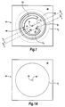
- FIGURES 1, 1A, 2 and 3 therein is illustrated the integrated stacked patch antenna polarizer 10 of the present invention.
- a two-layer, 90° microstrip coupler 20 is mounted to a hi-band patch P H and a die-electric substrate 94 of approximately 0.100 inch thickness (FIGURES 1 and 2).
- a lo-band patch P L (FIGURE 1A) and a die-electric substrate 92 of approximately 0.250 inch thickness is mounted adjacent to and below the hi-band patch P H and the substrate 94 (FIGURE 2).
- the coupler 20 includes a 0 output terminal 22 and a -90° output terminal 24 connected by two conducting pins 52 and 54 (or plated through hole conductors in the substrates) directly to the groundplane 200 of the lo-band patch P L (FIGURES 1,2 and 3).
- the groundplane 200 is connected to an outer shell of the input connector 50 (FIGURE 3).
- the hi-band patch P H is the groundplane for the coupler 20 and is nearly transparent to the radiation from the hi-band patch P H and the lo-band patch P L of the antenna 10.
- An input terminal 26 of the coupler 20 is connected to the input connector 50 by means of a coaxial line 56 through the center of the antenna 10 (FIGURES 1 and 3). The center of the antenna 10 is at zero RF potential.
- the coupler 20 includes a lower dielectric substrate 96 of approximately 0.047 inch thickness and an upper dielectric substrate 98 of approximately 0.020 inch thickness (FIGURES 5 and 6).
- a lower coupler C L connects the input terminal 26 with the -90° output terminal 24 (FIGURE 4A).
- the lower coupler C L includes a microstrip conductor disposed between the upper dielectric substrate 98 and the lower dielectric substrate 96 in an arcuate path from terminal 24 to terminal 26 (FIGURES 4A, 5 and 6).
- An upper coupler C U connects the 0° isolation output terminal 22 with a quarter wave length open stub C S (FIGURES 4, 5 and 6).
- the upper coupler C U includes a microstrip conductor disposed on top of the upper dielectric substrate 98 in an arcuate path from terminal 22 to the open stub C S (FIGURE 4). Intermediate between isolated terminal 22 and the open stub C S is a 50-ohm surface mounted resistor 60 (FIGURE 4). The isolation terminal 22 is terminated in the surface mounted 50-ohm resistor 60 to ground through the open stub C S (FIGURE 4).
- the microstrip coupler 20 provides an input for the hi-band patch P H and lo-band patch P L to excite radiation in two orthogonal linear polarizations in quadrature from the antenna 10 (FIGURES 1 and 2).
Applications Claiming Priority (2)
| Application Number | Priority Date | Filing Date | Title |
|---|---|---|---|
| US694855 | 1985-01-25 | ||
| US08/694,855 US5815119A (en) | 1996-08-08 | 1996-08-08 | Integrated stacked patch antenna polarizer circularly polarized integrated stacked dual-band patch antenna |
Publications (1)
| Publication Number | Publication Date |
|---|---|
| EP0823749A1 true EP0823749A1 (fr) | 1998-02-11 |
Family
ID=24790532
Family Applications (1)
| Application Number | Title | Priority Date | Filing Date |
|---|---|---|---|
| EP97250201A Ceased EP0823749A1 (fr) | 1996-08-08 | 1997-07-01 | Antenne à microbande intégrée de type pavé |
Country Status (4)
| Country | Link |
|---|---|
| US (1) | US5815119A (fr) |
| EP (1) | EP0823749A1 (fr) |
| JP (1) | JPH1098332A (fr) |
| AU (1) | AU717962B2 (fr) |
Cited By (3)
| Publication number | Priority date | Publication date | Assignee | Title |
|---|---|---|---|---|
| WO2002063715A1 (fr) * | 2001-02-05 | 2002-08-15 | Bluetronics Ab | Antenne a plaque pour blue tooth et wlan |
| WO2009093980A1 (fr) * | 2008-01-22 | 2009-07-30 | Agency For Science, Technology & Research | Antenne large bande en plage à polarisation circulaire |
| CN113131206A (zh) * | 2021-03-25 | 2021-07-16 | 西安博瑞集信电子科技有限公司 | 一种基于ltcc的圆极化微带天线 |
Families Citing this family (11)
| Publication number | Priority date | Publication date | Assignee | Title |
|---|---|---|---|---|
| US5969681A (en) * | 1998-06-05 | 1999-10-19 | Ericsson Inc. | Extended bandwidth dual-band patch antenna systems and associated methods of broadband operation |
| SE512439C2 (sv) * | 1998-06-26 | 2000-03-20 | Allgon Ab | Dubbelbandsantenn |
| US6404401B2 (en) | 2000-04-28 | 2002-06-11 | Bae Systems Information And Electronic Systems Integration Inc. | Metamorphic parallel plate antenna |
| US7071881B1 (en) * | 2004-10-04 | 2006-07-04 | Lockheed Martin Corporation | Circular antenna polarization via stadium configured active electronically steerable array |
| US7994999B2 (en) * | 2007-11-30 | 2011-08-09 | Harada Industry Of America, Inc. | Microstrip antenna |
| JP5344736B2 (ja) | 2008-02-20 | 2013-11-20 | 太陽誘電株式会社 | 基材、通信モジュール、および通信装置 |
| US10211535B2 (en) * | 2015-07-20 | 2019-02-19 | The Regents Of The University Of California | Low-profile circularly-polarized single-probe broadband antenna |
| US10069208B2 (en) | 2015-12-10 | 2018-09-04 | Taoglas Group Holdings Limited | Dual-frequency patch antenna |
| CN112736420A (zh) * | 2020-10-15 | 2021-04-30 | 天津津航计算技术研究所 | 一种电阻加载的Klopfenstein渐变线轮廓超宽带天线 |
| CN112259945B (zh) * | 2020-10-15 | 2021-12-17 | 西安博瑞集信电子科技有限公司 | 一种能够与标准PCB工艺兼容的3dB正交定向耦合器电路 |
| CN116014431B (zh) * | 2023-03-07 | 2023-09-19 | 电子科技大学 | 一种同时多路耦合馈电的宽带多线/圆极化可重构天线 |
Citations (8)
| Publication number | Priority date | Publication date | Assignee | Title |
|---|---|---|---|---|
| US4089003A (en) * | 1977-02-07 | 1978-05-09 | Motorola, Inc. | Multifrequency microstrip antenna |
| US4218682A (en) * | 1979-06-22 | 1980-08-19 | Nasa | Multiple band circularly polarized microstrip antenna |
| EP0188087A1 (fr) * | 1984-12-18 | 1986-07-23 | Texas Instruments Incorporated | Système d'antennes à microbandes |
| US4827271A (en) * | 1986-11-24 | 1989-05-02 | Mcdonnell Douglas Corporation | Dual frequency microstrip patch antenna with improved feed and increased bandwidth |
| US4924236A (en) * | 1987-11-03 | 1990-05-08 | Raytheon Company | Patch radiator element with microstrip balian circuit providing double-tuned impedance matching |
| US5006859A (en) * | 1990-03-28 | 1991-04-09 | Hughes Aircraft Company | Patch antenna with polarization uniformity control |
| US5165109A (en) * | 1989-01-19 | 1992-11-17 | Trimble Navigation | Microwave communication antenna |
| EP0542595A1 (fr) * | 1991-11-14 | 1993-05-19 | Dassault Electronique | Dispositif d'antenne microruban perfectionné, notamment pour transmissions téléphoniques par satellite |
Family Cites Families (9)
| Publication number | Priority date | Publication date | Assignee | Title |
|---|---|---|---|---|
| US3605097A (en) * | 1969-07-14 | 1971-09-14 | Textron Inc | End-loaded filament antenna |
| US4067016A (en) * | 1976-11-10 | 1978-01-03 | The United States Of America As Represented By The Secretary Of The Navy | Dual notched/diagonally fed electric microstrip dipole antennas |
| GB2198290B (en) * | 1986-11-29 | 1990-05-09 | Stc Plc | Dual band circularly polarised antenna with hemispherical coverage |
| US5099249A (en) * | 1987-10-13 | 1992-03-24 | Seavey Engineering Associates, Inc. | Microstrip antenna for vehicular satellite communications |
| US5121127A (en) * | 1988-09-30 | 1992-06-09 | Sony Corporation | Microstrip antenna |
| JPH03263903A (ja) * | 1989-04-28 | 1991-11-25 | Misao Haishi | 小形アンテナ |
| US5153600A (en) * | 1991-07-01 | 1992-10-06 | Ball Corporation | Multiple-frequency stacked microstrip antenna |
| US5444452A (en) * | 1992-07-13 | 1995-08-22 | Matsushita Electric Works, Ltd. | Dual frequency antenna |
| US5408241A (en) * | 1993-08-20 | 1995-04-18 | Ball Corporation | Apparatus and method for tuning embedded antenna |
-
1996
- 1996-08-08 US US08/694,855 patent/US5815119A/en not_active Expired - Fee Related
-
1997
- 1997-07-01 EP EP97250201A patent/EP0823749A1/fr not_active Ceased
- 1997-07-21 AU AU28767/97A patent/AU717962B2/en not_active Ceased
- 1997-08-07 JP JP9224497A patent/JPH1098332A/ja active Pending
Patent Citations (9)
| Publication number | Priority date | Publication date | Assignee | Title |
|---|---|---|---|---|
| US4089003A (en) * | 1977-02-07 | 1978-05-09 | Motorola, Inc. | Multifrequency microstrip antenna |
| US4218682A (en) * | 1979-06-22 | 1980-08-19 | Nasa | Multiple band circularly polarized microstrip antenna |
| EP0188087A1 (fr) * | 1984-12-18 | 1986-07-23 | Texas Instruments Incorporated | Système d'antennes à microbandes |
| US4660048A (en) * | 1984-12-18 | 1987-04-21 | Texas Instruments Incorporated | Microstrip patch antenna system |
| US4827271A (en) * | 1986-11-24 | 1989-05-02 | Mcdonnell Douglas Corporation | Dual frequency microstrip patch antenna with improved feed and increased bandwidth |
| US4924236A (en) * | 1987-11-03 | 1990-05-08 | Raytheon Company | Patch radiator element with microstrip balian circuit providing double-tuned impedance matching |
| US5165109A (en) * | 1989-01-19 | 1992-11-17 | Trimble Navigation | Microwave communication antenna |
| US5006859A (en) * | 1990-03-28 | 1991-04-09 | Hughes Aircraft Company | Patch antenna with polarization uniformity control |
| EP0542595A1 (fr) * | 1991-11-14 | 1993-05-19 | Dassault Electronique | Dispositif d'antenne microruban perfectionné, notamment pour transmissions téléphoniques par satellite |
Cited By (3)
| Publication number | Priority date | Publication date | Assignee | Title |
|---|---|---|---|---|
| WO2002063715A1 (fr) * | 2001-02-05 | 2002-08-15 | Bluetronics Ab | Antenne a plaque pour blue tooth et wlan |
| WO2009093980A1 (fr) * | 2008-01-22 | 2009-07-30 | Agency For Science, Technology & Research | Antenne large bande en plage à polarisation circulaire |
| CN113131206A (zh) * | 2021-03-25 | 2021-07-16 | 西安博瑞集信电子科技有限公司 | 一种基于ltcc的圆极化微带天线 |
Also Published As
| Publication number | Publication date |
|---|---|
| US5815119A (en) | 1998-09-29 |
| JPH1098332A (ja) | 1998-04-14 |
| AU717962B2 (en) | 2000-04-06 |
| AU2876797A (en) | 1998-02-12 |
Similar Documents
| Publication | Publication Date | Title |
|---|---|---|
| US4710775A (en) | Parasitically coupled, complementary slot-dipole antenna element | |
| US6133878A (en) | Microstrip array antenna | |
| JP3093715B2 (ja) | 共振器付着型マイクロストリップダイポールアンテナアレイ | |
| US5786793A (en) | Compact antenna for circular polarization | |
| EP0447218B1 (fr) | Antenne microbande pour plusieurs fréquences | |
| US3803623A (en) | Microstrip antenna | |
| JP4440266B2 (ja) | 広帯域フェーズドアレイ放射器 | |
| US4924236A (en) | Patch radiator element with microstrip balian circuit providing double-tuned impedance matching | |
| US4812855A (en) | Dipole antenna with parasitic elements | |
| US7782266B2 (en) | Circularly-polarized dielectric resonator antenna | |
| EP0685900B1 (fr) | Antenne | |
| US5111211A (en) | Broadband patch antenna | |
| US10978812B2 (en) | Single layer shared aperture dual band antenna | |
| US5815119A (en) | Integrated stacked patch antenna polarizer circularly polarized integrated stacked dual-band patch antenna | |
| US5442367A (en) | Printed antenna with strip and slot radiators | |
| JPH1056322A (ja) | マイクロストリップ給電円筒形スロット・アンテナ | |
| CN109219906A (zh) | 天线装置 | |
| US8106846B2 (en) | Compact circular polarized antenna | |
| Wen et al. | A wideband series-fed circularly polarized differential antenna by using crossed open slot-pairs | |
| US5126751A (en) | Flush mount antenna | |
| JPH06268432A (ja) | 直線偏波用ループアンテナ | |
| Kai-Fong | Microstrip patch antennas—Basic properties and some recent advances | |
| USH1877H (en) | Polarization diverse phase dispersionless broadband antenna | |
| US7821462B1 (en) | Compact, dual-polar broadband monopole | |
| JPH01147905A (ja) | 平面アンテナ |
Legal Events
| Date | Code | Title | Description |
|---|---|---|---|
| PUAI | Public reference made under article 153(3) epc to a published international application that has entered the european phase |
Free format text: ORIGINAL CODE: 0009012 |
|
| AK | Designated contracting states |
Kind code of ref document: A1 Designated state(s): DE FR GB IT |
|
| 17P | Request for examination filed |
Effective date: 19980811 |
|
| AKX | Designation fees paid |
Free format text: DE FR GB IT |
|
| RBV | Designated contracting states (corrected) |
Designated state(s): DE FR GB IT |
|
| RAP1 | Party data changed (applicant data changed or rights of an application transferred) |
Owner name: RAYTHEON COMPANY |
|
| 17Q | First examination report despatched |
Effective date: 20030124 |
|
| STAA | Information on the status of an ep patent application or granted ep patent |
Free format text: STATUS: THE APPLICATION HAS BEEN REFUSED |
|
| 18R | Application refused |
Effective date: 20030630 |