EP0822462B1 - Verfahren und Gerät zum Drucken mittels elektrischer Koagulation - Google Patents
Verfahren und Gerät zum Drucken mittels elektrischer Koagulation Download PDFInfo
- Publication number
- EP0822462B1 EP0822462B1 EP97902708A EP97902708A EP0822462B1 EP 0822462 B1 EP0822462 B1 EP 0822462B1 EP 97902708 A EP97902708 A EP 97902708A EP 97902708 A EP97902708 A EP 97902708A EP 0822462 B1 EP0822462 B1 EP 0822462B1
- Authority
- EP
- European Patent Office
- Prior art keywords
- positive electrode
- ink
- electrode active
- oily substance
- active surface
- Prior art date
- Legal status (The legal status is an assumption and is not a legal conclusion. Google has not performed a legal analysis and makes no representation as to the accuracy of the status listed.)
- Expired - Lifetime
Links
Images


Classifications
-
- B—PERFORMING OPERATIONS; TRANSPORTING
- B41—PRINTING; LINING MACHINES; TYPEWRITERS; STAMPS
- B41J—TYPEWRITERS; SELECTIVE PRINTING MECHANISMS, i.e. MECHANISMS PRINTING OTHERWISE THAN FROM A FORME; CORRECTION OF TYPOGRAPHICAL ERRORS
- B41J2/00—Typewriters or selective printing mechanisms characterised by the printing or marking process for which they are designed
- B41J2/385—Typewriters or selective printing mechanisms characterised by the printing or marking process for which they are designed characterised by selective supply of electric current or selective application of magnetism to a printing or impression-transfer material
- B41J2/39—Typewriters or selective printing mechanisms characterised by the printing or marking process for which they are designed characterised by selective supply of electric current or selective application of magnetism to a printing or impression-transfer material using multi-stylus heads
-
- B—PERFORMING OPERATIONS; TRANSPORTING
- B41—PRINTING; LINING MACHINES; TYPEWRITERS; STAMPS
- B41C—PROCESSES FOR THE MANUFACTURE OR REPRODUCTION OF PRINTING SURFACES
- B41C1/00—Forme preparation
- B41C1/10—Forme preparation for lithographic printing; Master sheets for transferring a lithographic image to the forme
- B41C1/105—Forme preparation for lithographic printing; Master sheets for transferring a lithographic image to the forme by electrocoagulation, by electro-adhesion or by electro-releasing of material, e.g. a liquid from a gel
-
- B—PERFORMING OPERATIONS; TRANSPORTING
- B41—PRINTING; LINING MACHINES; TYPEWRITERS; STAMPS
- B41J—TYPEWRITERS; SELECTIVE PRINTING MECHANISMS, i.e. MECHANISMS PRINTING OTHERWISE THAN FROM A FORME; CORRECTION OF TYPOGRAPHICAL ERRORS
- B41J2/00—Typewriters or selective printing mechanisms characterised by the printing or marking process for which they are designed
- B41J2/385—Typewriters or selective printing mechanisms characterised by the printing or marking process for which they are designed characterised by selective supply of electric current or selective application of magnetism to a printing or impression-transfer material
- B41J2/3855—Electrographic print heads using processes not otherwise provided for, e.g. electrolysis
Definitions
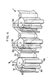
- the negative and positive electrodes, the positive electrode coating device, ink injector and soft rubber squeegee are arranged to define a printing unit and several printing units each using a coloring agent of different color are disposed in tandem relation to produce several differently colored images of coagulated colloid which are transferred at respective transfer stations onto the substrate in superimposed relation to provide the desired polychromic image.
- the printing units can be arranged around a single roller (a pressure roller) adapted to bring the substrate into contact with the dots of colored, coagulated colloid produced by each printing unit, and the substrate which is in the form of a continuous web is partially wrapped around the roller and passed through the respective transfer stations for being imprinted with the differently colored images in superimposed relation.
- an electrocoagulation printing apparatus comprising: a positive electrode made of an electrolytically inert metal and having a continuous passiavated surface as a positive electrode active surface moving along a predetermined path; an ink feeding part which supplies electrocoagulation printing ink onto said positive electrode active surface; a negative electrode for reproducing on said positive electrode active surface dots of coagulated ink by electrocoagulation; and a transfer part which brings a substrate into contact with the dots of coagulated ink to cause transfer of the dots of coagulated ink from said positive electrode active surface to said substrate; characterised by a fogging ink removing portion which supplies a first oily substance onto said positive electrode active surface and removes fogging ink mixed with the first oily substance from said positive electrode active surface without altering said dots of coagulated ink.
- a printing head 30 serving as negative electrodes is provided at the downstream side of the oiler 14 in the direction indicated by arrow A in Fig. 1, a predetermined distance apart from the surface 12B of the positive electrode (i.e., at a gap between the surface 12B and the printing head 30) and parallel to the revolving cylinder shaft 12A (i.e., in the longitudinal direction of the revolving cylinder shaft 12A).
- the printing head 30 is provided with a large number of negative electrodes (i.e., pin electrodes), not shown, of which tip ends are perpendicularly directed toward the surface 12B so as to obtain a resolution of at least 200dpi.
- the first squeegee 34 and the second squeegee 36 are each made from soft rubber having a wedge-shaped (acute-angled triangular) cross sectional configuration and extending along the direction parallel to the revolving cylinder 12 (i.e., the longitudinal direction of the cylinder 12). Respective acute angle portions of the squeegees 34, 36 are brought into slide-contact with the surface 12B.
- the oily substance supply port 38 is, in the same manner as the inker 32, disposed in the vicinity of the upper portion of the surface 12B by a predetermined distance apart the surface 12B so that the first oily substance 140 flows downward on the surface 12B due to its gravity,
- the basic structure of the oil cascade unit 40 is as shown in Fig. 1, but the oil cascade unit 40 is shown as a black box in Fig. 2.
- the second oily substance is applied onto the surface 12B of the positive electrode by the oiler 14 equipped with a distribution roller extending parallel to the revolving cylinder 12 and having a peripheral coating comprising an oxide ceramic material.
- the second oily substance is applied onto the ceramic coating to form a film of the second oily substance uniformly covering the surface of the ceramic coating, the film of the second oily substance breaks down into micro-droplets having substantially uniform size and distribution, and the micro-droplets are transferred from the ceramic coating onto the surface 12B of the positive electrode via a transfer roll.
- the micro-droplets of the second oily substance 100 transferred onto the positive electrode surface 12B by the second transfer roller 20 of the oiler 14 have substantially uniform distribution on the surface 12B.
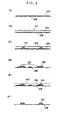
- step S40 in Fig. 7 the non-coagulated ink not associated with the dots and the micro-droplets of the second oily substance are scraped from the positive electrode surface.
- the most part of the non-coagulated ink 110 is removed from the surface 12B by scraping the surface 12B with the first squeegee 34 and the dots 120 of coagulated ink are brought into a sufficiently uncovered state.
- the unscraped non-coagulated ink 110 and a portion of dots of the coagulated ink scraped by the squeegee remain, as the fogging ink 130, on the surface 12B.
- This state is shown in Fig. 3(D).
- the non-coagulated ink 110 removed by the first squeegee 34 is collected to be circulated as described above.
- the first oily substance is applied onto the surface of the positive electrode.
- the first oily substance 140 is continuously supplied onto the surface 12B of the positive electrode from the oily substance supply port 38.
- the first oily substance 140 may be of the same type as or the different type from the second oily substance.
- oleic acid which is the same as that used for the second oily substance is used for the first oily substance.
- Fig. 3(E) shows the state in which the first oily substance is supplied onto the surface 12B.
Landscapes
- Chemical & Material Sciences (AREA)
- Dispersion Chemistry (AREA)
- Engineering & Computer Science (AREA)
- Manufacturing & Machinery (AREA)
- Chemical Kinetics & Catalysis (AREA)
- Electrochemistry (AREA)
- Printing Methods (AREA)
- Printers Or Recording Devices Using Electromagnetic And Radiation Means (AREA)
- Battery Electrode And Active Subsutance (AREA)
Claims (14)
- Ein Verfahren zum Drucken mittels elektrischer Koagulation mit den folgenden Schritten:(a) Bilden einer positiven Elektrode (12) aus einem elektrolytisch inerten Metall und mit einer kontinuierlichen, passivierten Oberfläche als aktive Fläche einer positiven Oberfläche (12B), die sich entlang eines vorgegebenen Wegs bewegt;(b) Bilden einer Vielzahl von Punkten aus einem koagulierten Farbstoff, die das gewünschte Bild wiedergeben, durch Elektrokoagulation einer elektrisch zu koagulierenden Druckfarbe (110);(c) In Kontakt Bringen eines Substrats (80) mit den Punkten koagulierten Farbstoffs zur Verursachung eines Transfers der Punkte des koagulierten Farbstoffs von der aktiven Oberfläche der positiven Elektrode (12B) auf das Substrat (80),
gekennzeichnet durch zwischen den Schritten (b) und (c):(d) Aufbringen einer ersten öligen Substanz (140) auf die aktive Oberfläche (12B) der positiven Elektrode zum Vermischen der ersten öligen Substanz (140) mit Schleierfarbe (130) in einem Nicht-Bildbereich;(e) Entfernen des Schleierfarbstoffs (13), der mit der ersten öligen Substanz vermischt ist, von dem Nicht-Bildbereich der aktiven Oberfläche (12B) ohne Beeinträchtigen der Punkte des koagulierten Farbstoffs. - Ein Verfahren zum Drucken mittels elektrischer Koagulation, bei dem das Elektrokoagulationsverfahren nach Anspruch 1 angewendet wird, wobei
eine Mehrzahl von Druckstufen definiert werden, die an vorbestimmten Orten entlang des Weges angeordnet sind und die jeweils eine andere Elektrokoagulations-Druckfarbe (110) verwenden, und die Schritte (b), (d), (e) und (c) mehrmals wiederholt werden, wodurch mehrere Bilder an dem jeweiligen Transferteil auf dem Substrat reproduziert werden. - Ein Verfahren zum Drucken mittels elektrischer Koagulation nach Anspruch 1 oder Anspruch 2, dadurch gekennzeichnet, dass die erste ölige Substanz (140) aus der Gruppe bestehend aus ungesättigten Fettsäuren und ungesättigten pflanzlichen Ölen gewählt ist.
- Ein Verfahren zum Drucken mittels elektrischer Koagulation nach Anspruch 1 oder Anspruch 2, dadurch gekennzeichnet, dass der Schritt (b) die folgenden Schritte aufweist:(i) Vorsehen einer Mehrzahl von elektrolytisch inerten negativen Elektroden, die voneinander elektrisch isoliert und in geradliniger Ausrichtung angeordnet sind, um eine Reihe von entsprechenden aktiven Flächen negativer Elektroden zu bilden, die in einer Ebene parallel zu der Längsachse der positiven Elektrode (12) und mit einem konstanten vorgegebenen Spalt von der aktiven Fläche (12B) der positiven Elektrode beabstandet angeordnet sind, wobei die negativen Elektroden voneinander um eine Strecke beabstandet sind, die wenigstens dem Elektrodenabstand gleich ist;(ii) Beschichten der aktiven Fläche (12B) der positiven Elektrode mit einer zweiten öligen Substanz zur Bildung von Mikro-Tröpfchen der zweiten öligen Substanz auf der Oberfläche (12B);(iii) Füllen des Elektrodenspalts mit der Elektrokoagulationsdruckfarbe (110);(iv) elektrisches Beaufschlagen ausgewählter der negativen Elektroden zum Bewirken einer selektiven Koagulation der Elektrokoagulationsfarbe (110) und Anhaften der koagulierten Druckfarbe auf die aktive Oberfläche (12B) der positiven Elektrode, die mit der zweiten öligen Substanz beschichtet ist, gegenüberliegend zu de aktiven Elektrodenflächen der elektrisch beaufschlagten negativen Elektroden während die positive Elektrode (13) gedreht wird, wodurch sich Punkte der koagulierten Druckfarbe bilden; und(v) Entfernen aller verbleibender nicht-koagulierter Druckfarbe von der aktiven Fläche (12B) der positiven Elektrode.
- Ein Verfahren zum Drucken mittels elektrischer Koagulation nach Anspruch 4, dadurch gekennzeichnet, dass Schritt (b) (ii) die folgenden Schritte aufweist:Vorsehen erster und zweiter Distributionswalzen (22, 24), die sich parallel zu der positiven Elektrode (12) erstrecken und jeweils eine Außenbeschichtung bestehend aus einem Keramikoxidmaterial haben;Aufbringen einer öligen Substanz auf die keramische Beschichtung der ersten Distributionswalze (22) zum Bilden eines Films der zweiten öligen Substanz, der die Fläche der keramischen Beschichtung gleichförmig belegt, wobei der aus der zweiten öligen Substanz bestehende Film wenigstens teilweise in Mikro-Tröpfchen mit einer im wesentlichen gleichmäßigen Größe und Verteilung zerfällt;Transferieren des wenigstens teilweise zerfallenen Films von der ersten Distributionswalze (22) auf die zweite Distributionswalze (24), um ein vollständiges Zerfallen des Films auf der keramischen Beschichtung der zweiten Distributionswalze (24) in die Mikro-Tröpfchen mit im wesentlichen gleichförmiger Größe und Verteilung zu bewirken; undTransferieren der Mikro-Tröpfchen von der keramischen Beschichtung der zweiten Distributionswalze (24) auf die aktive Fläche (12B) der positiven Elektrode.
- Ein Verfahren zum Drucken mittels elektrischer Koagulation nach einem der Ansprüche 1, 2 oder 4, dadurch gekennzeichnet, dass eine Mischung von Schleierfarbe, die von der aktiven Fläche (12B) der positiven Elektrode entfernt ist, und der ersten öligen Substanz (140) gesammelt wird, die erste ölige Substanz (140) von der gesammelten Mischung getrennt wird und die abgetrennte ölige Substanz wieder auf die aktive Fläche (12B) der positiven Elektrode aufgebracht wird.
- Ein Verfahren zum Drucken mittels elektrischer Koagulation nach Anspruch 6, dadurch gekennzeichnet, dass die erste ölige Substanz (140) von der Mischung durch Zugeben von Wasser zu der Mischung zur Bildung einer wässrigen Phase, die die entfernte Schleierfarbe (130) enthält und eine ölige Phase, die die erste ölige Substanz (140) enthält, Trennen der öligen Phase von der wässrigen Phase, Filtern der abgetrennten öligen Phase zum Entfernen der suspendierten Festteile und Rückgewinnen der gefilterten öligen Phase zur erneuten Aufbringung auf die aktive Fläche (12B) der positiven Elektrode (12B).
- Eine Vorrichtung (10) zum Drucken mittels elektrischer Koagulation, mit:gekennzeichnet durcheiner positiven Elektrode (12), die aus einem elektrolytisch inerten Metall gefertigt ist und eine kontinuierliche, passivierte Fläche als aktive Fläche (12B) der positiven Elektrode hat und sich entlang eines vorgegebenen Wegs bewegt,einem Farbzufuhrteil (32), das Elektrokoagulationsdruckfarbe (110) auf die aktive Fläche (12B) der positiven Elektrode aufbringt,einer negative Elektrode zum Reproduzieren von Punkten der Koagulationsfarbe auf der aktiven Fläche (12b) der positiven Elektrode durch Elektrokoagulation, undeinem Transferteil (70), das ein Substrat (80) in Berührung mit den Punkten koagulierter Druckfarbe bringt, um einen Transfer der Punkte koagulierter Farbe von der aktiven Fläche (12B) der positiven Elektrode auf das Substrat (80) zu bewirken,
einen Schleierfarbenentfernungsabschnitt (40), der eine erste ölige Substanz (140) auf den Nicht-Bildbereich der aktiven Fläche (12B) der positiven Elektrode aufbringt und mit der erst öligen Substanz vermischte Schleierfarbe (130) von dem Nicht-Bildbereich der aktiven Fläche (12B) entfernt, ohne die Punkte der koagulierten Farbe zu beeinflussen. - Eine Vorrichtung (10) zum Drucken mittels elektrischer Koagulation nach Anspruch 8, gekennzeichnet durch einen Beschichtungsteil (14) zum Beschichten der aktiven Fläche (12B) der positiven Elektrode mit einer zweiten öligen Substanz.
- Eine Vorrichtung (10) zum Drucken mittels elektrischer Koagulation nach Anspruch 8, gekennzeichnet durch Zirkulationsmittel (44, 46, 52, 54), in denen ein Gemisch aus der Schleierfarbe (130), die von der aktiven Fläche (12B) der positiven Elektrode entfernt worden ist, und der ersten öligen Substanz (140) gesammelt wird, die erste ölige Substanz (140) aus dem gesammelten Gemisch abgetrennt wird und die abgetrennte erste ölige Substanz (140) wieder auf die aktive Fläche (12B) der positiven Elektrode aufgebracht wird.
- Ein System zum Drucken mittels elektrischer Koagulation, mit:gekennzeichnet durchwenigstens einer positiven Elektrode (12, 12'), die aus einem elektrolytisch inerten Metall gefertigt ist und eine kontinuierliche, passivierte Fläche als aktive Fläche (12B) der positiven Elektrode hat und sich entlang eines vorgegebenen Wegs bewegt,einer Mehrzahl von Farbzufuhrteilen(32), die Elektrokoagulationsdruckfarbe (110) auf die aktive Fläche (12B) der positiven Elektrode aufbringen,einer Mehrzahl von negativen Elektroden zum Reproduzieren von Punkten der Koagulationsfarbe auf der aktiven Fläche (12b) der positiven Elektrode durch Elektrokoagulation, undeiner Mehrzahl von Transferteilen (70), die ein Substrat (80) in Berührung mit den Punkten koagulierter Druckfarbe bringen, um einen Transfer der Punkte koagulierter Farbe von der aktiven Fläche (12B) der positiven Elektrode auf das Substrat (80) zu bewirken,
eine Mehrzahl von Schleierfarbenentfernungsabschnitten, die eine erste ölige Substanz (140) auf den Nicht-Bildbereich der aktiven Fläche (12B) der positiven Elektrode aufbringen und mit der ersten öligen Substanz vermischte Schleierfarbe (130) von dem Nicht-Bildbereich der aktiven Fläche (12B) entfernen, ohne die Punkte der koagulierten Farbe zu beeinflussen. - System zum Drucken mittels elektrischer Koagulation nach Anspruch 11 mit einer Mehrzahl von Druckstationen, dadurch gekennzeichnet, dass jede Druckstation (10) die positive Elektrode (12), eine aus der Mehrzahl der Farbzufuhrteile (32), eine aus der Mehrzahl von negativen Elektroden, eine aus der Mehrzahl von Schleierfarbenentfernungsabschnitten (40) und eine aus der Mehrzahl von Transferteilen (70) aufweist.
- System zum Drucken mittels elektrischer Koagulation nach Anspruch 11 mit der positiven Elektrode (12'), und einer Mehrzahl von Druckstationen (88), dadurch gekennzeichnet, dass jede der Druckstationen (88) eine aus der Mehrzahl der Farbzufuhrteile (32), eine aus der Mehrzahl von negativen Elektroden, eine aus der Mehrzahl von Schleierfarbenentfernungsabschnitten (40) und eine aus der Mehrzahl von Transferteilen (70) aufweist und weiter dadurch gekennzeichnet, dass die Mehrzahl von Druckstationen (88) entlang des Weges der positiven Elektrode (12') angeordnet sind.
- System zum Drucken mittels elektrischer Koagulation nach einem der Ansprüche 11 bis 13, gekennzeichnet durch einen Beschichtungsteil (14) zum Beschichten der aktiven Fläche (12B) der positiven Elektrode mit einer zweiten öligen Substanz.
Applications Claiming Priority (3)
| Application Number | Priority Date | Filing Date | Title |
|---|---|---|---|
| CA 2169669 CA2169669C (en) | 1996-02-16 | 1996-02-16 | Method of preventing formation of undesirable background on electrocoagulation printed images |
| CA2169669 | 1996-02-16 | ||
| PCT/JP1997/000418 WO1997030379A1 (fr) | 1996-02-16 | 1997-02-17 | Procede et dispositif d'impression par coagulation electrique |
Publications (3)
| Publication Number | Publication Date |
|---|---|
| EP0822462A1 EP0822462A1 (de) | 1998-02-04 |
| EP0822462A4 EP0822462A4 (de) | 1999-05-06 |
| EP0822462B1 true EP0822462B1 (de) | 2003-05-02 |
Family
ID=4157588
Family Applications (1)
| Application Number | Title | Priority Date | Filing Date |
|---|---|---|---|
| EP97902708A Expired - Lifetime EP0822462B1 (de) | 1996-02-16 | 1997-02-17 | Verfahren und Gerät zum Drucken mittels elektrischer Koagulation |
Country Status (5)
| Country | Link |
|---|---|
| EP (1) | EP0822462B1 (de) |
| AU (1) | AU1672997A (de) |
| CA (1) | CA2169669C (de) |
| DE (1) | DE69721409T2 (de) |
| WO (1) | WO1997030379A1 (de) |
Families Citing this family (2)
| Publication number | Priority date | Publication date | Assignee | Title |
|---|---|---|---|---|
| CA2224339C (en) * | 1997-12-10 | 2003-02-11 | Pierre Castegnier | Printing head system for use in an electrocoagulation printing apparatus |
| JP3067771B1 (ja) * | 1999-07-12 | 2000-07-24 | ヤマハ株式会社 | 印刷装置 |
Family Cites Families (2)
| Publication number | Priority date | Publication date | Assignee | Title |
|---|---|---|---|---|
| CA1279603C (en) * | 1986-02-20 | 1991-01-29 | Adrien Castegnier | Monochromic and polychromic printing of an image reproduced by electro-coagulation of a colloid |
| CA1334017C (en) * | 1989-04-12 | 1995-01-17 | Adrien Castegnier | High-speed electrocoagulation printing method and apparatus |
-
1996
- 1996-02-16 CA CA 2169669 patent/CA2169669C/en not_active Expired - Fee Related
-
1997
- 1997-02-17 AU AU16729/97A patent/AU1672997A/en not_active Abandoned
- 1997-02-17 EP EP97902708A patent/EP0822462B1/de not_active Expired - Lifetime
- 1997-02-17 DE DE69721409T patent/DE69721409T2/de not_active Expired - Fee Related
- 1997-02-17 WO PCT/JP1997/000418 patent/WO1997030379A1/ja active IP Right Grant
Also Published As
| Publication number | Publication date |
|---|---|
| EP0822462A1 (de) | 1998-02-04 |
| WO1997030379A1 (fr) | 1997-08-21 |
| CA2169669C (en) | 2001-01-23 |
| DE69721409D1 (de) | 2003-06-05 |
| CA2169669A1 (en) | 1997-08-17 |
| AU1672997A (en) | 1997-09-02 |
| DE69721409T2 (de) | 2003-11-13 |
| EP0822462A4 (de) | 1999-05-06 |
Similar Documents
| Publication | Publication Date | Title |
|---|---|---|
| US5727462A (en) | Multicolor dynamic printing method and apparatus | |
| CA1334017C (en) | High-speed electrocoagulation printing method and apparatus | |
| US5908541A (en) | Multicolor electrocoagulation printing method and apparatus | |
| EP0822462B1 (de) | Verfahren und Gerät zum Drucken mittels elektrischer Koagulation | |
| US5693206A (en) | Electrocoagulation printing apparatus | |
| US6045674A (en) | Intermittent electrocoagulation printing method and apparatus | |
| US5690803A (en) | Method of enhancing transfer of coagulated colloid onto a substrate during electrocoagulation printing | |
| EP0899094B1 (de) | Mehrfarben -Elektrokoagulationsdruckverfahren und Vorrichtung | |
| US5690801A (en) | Method of rendering an electrocoagulation printed image water-fast | |
| US5681436A (en) | Method of preventing formation of undesirable background on electrocoagulation printed images | |
| EP1084829B1 (de) | Elektrokoagulationsdruckverfahren und Vorrichtung zur Erzeugung von erhöhter Bildauflösung | |
| CA2214606C (en) | Method of preventing anode abrasion during electrocoagulation printing | |
| US6551481B2 (en) | Electrocoagulation printing method and apparatus providing color juxtaposition | |
| US5690802A (en) | Method of increasing coagulation efficiency during electrocoagulation printing | |
| CA2156978C (en) | Multicolor dynamic printing method and apparatus | |
| US5863402A (en) | Method of preventing anode abrasion during electrocoagulation printing | |
| CA2355458C (en) | Electrocoagulation printing method and apparatus providing color juxtaposition | |
| CA2194130C (en) | Method of enhancing transfer of coagulated colloid onto a substrate during electrocoagulation printing | |
| CA2194128C (en) | Method of increasing coagulation efficiency during electrocoagulation printing | |
| CA2194129C (en) | Method of rendering an electrocoagulation printed image water-fast | |
| EP1285748A2 (de) | Elektrokoagulationsdruckverfahren und Vorrichtung mit Farbennebeneinanderstellung | |
| CA2282188C (en) | Intermittent electrocoagulation printing method and apparatus | |
| CA2334265C (en) | Electrocoagulation printing method and apparatus providing enhanced image resolution | |
| US20030194624A1 (en) | Electrocoagulation printing method providing an image having enhanced optical density | |
| JP2002086788A (ja) | 間欠電気凝固印刷方法及び装置 |
Legal Events
| Date | Code | Title | Description |
|---|---|---|---|
| PUAI | Public reference made under article 153(3) epc to a published international application that has entered the european phase |
Free format text: ORIGINAL CODE: 0009012 |
|
| AK | Designated contracting states |
Kind code of ref document: A1 Designated state(s): DE FR GB IT |
|
| 17P | Request for examination filed |
Effective date: 19971022 |
|
| A4 | Supplementary search report drawn up and despatched |
Effective date: 19990318 |
|
| AK | Designated contracting states |
Kind code of ref document: A4 Designated state(s): DE FR GB IT |
|
| 17Q | First examination report despatched |
Effective date: 20011001 |
|
| GRAG | Despatch of communication of intention to grant |
Free format text: ORIGINAL CODE: EPIDOS AGRA |
|
| RTI1 | Title (correction) |
Free format text: ELECTRICAL COAGULATION PRINTING METHOD AND ELECTRICAL COAGULATION PRINTING APPARATUS |
|
| GRAG | Despatch of communication of intention to grant |
Free format text: ORIGINAL CODE: EPIDOS AGRA |
|
| GRAH | Despatch of communication of intention to grant a patent |
Free format text: ORIGINAL CODE: EPIDOS IGRA |
|
| GRAH | Despatch of communication of intention to grant a patent |
Free format text: ORIGINAL CODE: EPIDOS IGRA |
|
| GRAA | (expected) grant |
Free format text: ORIGINAL CODE: 0009210 |
|
| AK | Designated contracting states |
Designated state(s): DE FR GB IT |
|
| REG | Reference to a national code |
Ref country code: GB Ref legal event code: FG4D |
|
| REF | Corresponds to: |
Ref document number: 69721409 Country of ref document: DE Date of ref document: 20030605 Kind code of ref document: P |
|
| PGFP | Annual fee paid to national office [announced via postgrant information from national office to epo] |
Ref country code: FR Payment date: 20040210 Year of fee payment: 8 |
|
| PGFP | Annual fee paid to national office [announced via postgrant information from national office to epo] |
Ref country code: GB Payment date: 20040211 Year of fee payment: 8 |
|
| PGFP | Annual fee paid to national office [announced via postgrant information from national office to epo] |
Ref country code: DE Payment date: 20040226 Year of fee payment: 8 |
|
| ET | Fr: translation filed | ||
| PLBE | No opposition filed within time limit |
Free format text: ORIGINAL CODE: 0009261 |
|
| STAA | Information on the status of an ep patent application or granted ep patent |
Free format text: STATUS: NO OPPOSITION FILED WITHIN TIME LIMIT |
|
| 26N | No opposition filed |
Effective date: 20040203 |
|
| PG25 | Lapsed in a contracting state [announced via postgrant information from national office to epo] |
Ref country code: IT Free format text: LAPSE BECAUSE OF NON-PAYMENT OF DUE FEES Effective date: 20050217 Ref country code: GB Free format text: LAPSE BECAUSE OF NON-PAYMENT OF DUE FEES Effective date: 20050217 |
|
| PG25 | Lapsed in a contracting state [announced via postgrant information from national office to epo] |
Ref country code: DE Free format text: LAPSE BECAUSE OF NON-PAYMENT OF DUE FEES Effective date: 20050901 |
|
| GBPC | Gb: european patent ceased through non-payment of renewal fee |
Effective date: 20050217 |
|
| PG25 | Lapsed in a contracting state [announced via postgrant information from national office to epo] |
Ref country code: FR Free format text: LAPSE BECAUSE OF NON-PAYMENT OF DUE FEES Effective date: 20051031 |
|
| REG | Reference to a national code |
Ref country code: FR Ref legal event code: ST Effective date: 20051031 |