EP0822462B1 - Electrical coagulation printing method and electrical coagulation printing apparatus - Google Patents
Electrical coagulation printing method and electrical coagulation printing apparatus Download PDFInfo
- Publication number
- EP0822462B1 EP0822462B1 EP97902708A EP97902708A EP0822462B1 EP 0822462 B1 EP0822462 B1 EP 0822462B1 EP 97902708 A EP97902708 A EP 97902708A EP 97902708 A EP97902708 A EP 97902708A EP 0822462 B1 EP0822462 B1 EP 0822462B1
- Authority
- EP
- European Patent Office
- Prior art keywords
- positive electrode
- ink
- electrode active
- oily substance
- active surface
- Prior art date
- Legal status (The legal status is an assumption and is not a legal conclusion. Google has not performed a legal analysis and makes no representation as to the accuracy of the status listed.)
- Expired - Lifetime
Links
Images


Classifications
-
- B—PERFORMING OPERATIONS; TRANSPORTING
- B41—PRINTING; LINING MACHINES; TYPEWRITERS; STAMPS
- B41J—TYPEWRITERS; SELECTIVE PRINTING MECHANISMS, i.e. MECHANISMS PRINTING OTHERWISE THAN FROM A FORME; CORRECTION OF TYPOGRAPHICAL ERRORS
- B41J2/00—Typewriters or selective printing mechanisms characterised by the printing or marking process for which they are designed
- B41J2/385—Typewriters or selective printing mechanisms characterised by the printing or marking process for which they are designed characterised by selective supply of electric current or selective application of magnetism to a printing or impression-transfer material
- B41J2/39—Typewriters or selective printing mechanisms characterised by the printing or marking process for which they are designed characterised by selective supply of electric current or selective application of magnetism to a printing or impression-transfer material using multi-stylus heads
-
- B—PERFORMING OPERATIONS; TRANSPORTING
- B41—PRINTING; LINING MACHINES; TYPEWRITERS; STAMPS
- B41C—PROCESSES FOR THE MANUFACTURE OR REPRODUCTION OF PRINTING SURFACES
- B41C1/00—Forme preparation
- B41C1/10—Forme preparation for lithographic printing; Master sheets for transferring a lithographic image to the forme
- B41C1/105—Forme preparation for lithographic printing; Master sheets for transferring a lithographic image to the forme by electrocoagulation, by electro-adhesion or by electro-releasing of material, e.g. a liquid from a gel
-
- B—PERFORMING OPERATIONS; TRANSPORTING
- B41—PRINTING; LINING MACHINES; TYPEWRITERS; STAMPS
- B41J—TYPEWRITERS; SELECTIVE PRINTING MECHANISMS, i.e. MECHANISMS PRINTING OTHERWISE THAN FROM A FORME; CORRECTION OF TYPOGRAPHICAL ERRORS
- B41J2/00—Typewriters or selective printing mechanisms characterised by the printing or marking process for which they are designed
- B41J2/385—Typewriters or selective printing mechanisms characterised by the printing or marking process for which they are designed characterised by selective supply of electric current or selective application of magnetism to a printing or impression-transfer material
- B41J2/3855—Electrographic print heads using processes not otherwise provided for, e.g. electrolysis
Definitions
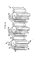
- the negative and positive electrodes, the positive electrode coating device, ink injector and soft rubber squeegee are arranged to define a printing unit and several printing units each using a coloring agent of different color are disposed in tandem relation to produce several differently colored images of coagulated colloid which are transferred at respective transfer stations onto the substrate in superimposed relation to provide the desired polychromic image.
- the printing units can be arranged around a single roller (a pressure roller) adapted to bring the substrate into contact with the dots of colored, coagulated colloid produced by each printing unit, and the substrate which is in the form of a continuous web is partially wrapped around the roller and passed through the respective transfer stations for being imprinted with the differently colored images in superimposed relation.
- an electrocoagulation printing apparatus comprising: a positive electrode made of an electrolytically inert metal and having a continuous passiavated surface as a positive electrode active surface moving along a predetermined path; an ink feeding part which supplies electrocoagulation printing ink onto said positive electrode active surface; a negative electrode for reproducing on said positive electrode active surface dots of coagulated ink by electrocoagulation; and a transfer part which brings a substrate into contact with the dots of coagulated ink to cause transfer of the dots of coagulated ink from said positive electrode active surface to said substrate; characterised by a fogging ink removing portion which supplies a first oily substance onto said positive electrode active surface and removes fogging ink mixed with the first oily substance from said positive electrode active surface without altering said dots of coagulated ink.
- a printing head 30 serving as negative electrodes is provided at the downstream side of the oiler 14 in the direction indicated by arrow A in Fig. 1, a predetermined distance apart from the surface 12B of the positive electrode (i.e., at a gap between the surface 12B and the printing head 30) and parallel to the revolving cylinder shaft 12A (i.e., in the longitudinal direction of the revolving cylinder shaft 12A).
- the printing head 30 is provided with a large number of negative electrodes (i.e., pin electrodes), not shown, of which tip ends are perpendicularly directed toward the surface 12B so as to obtain a resolution of at least 200dpi.
- the first squeegee 34 and the second squeegee 36 are each made from soft rubber having a wedge-shaped (acute-angled triangular) cross sectional configuration and extending along the direction parallel to the revolving cylinder 12 (i.e., the longitudinal direction of the cylinder 12). Respective acute angle portions of the squeegees 34, 36 are brought into slide-contact with the surface 12B.
- the oily substance supply port 38 is, in the same manner as the inker 32, disposed in the vicinity of the upper portion of the surface 12B by a predetermined distance apart the surface 12B so that the first oily substance 140 flows downward on the surface 12B due to its gravity,
- the basic structure of the oil cascade unit 40 is as shown in Fig. 1, but the oil cascade unit 40 is shown as a black box in Fig. 2.
- the second oily substance is applied onto the surface 12B of the positive electrode by the oiler 14 equipped with a distribution roller extending parallel to the revolving cylinder 12 and having a peripheral coating comprising an oxide ceramic material.
- the second oily substance is applied onto the ceramic coating to form a film of the second oily substance uniformly covering the surface of the ceramic coating, the film of the second oily substance breaks down into micro-droplets having substantially uniform size and distribution, and the micro-droplets are transferred from the ceramic coating onto the surface 12B of the positive electrode via a transfer roll.
- the micro-droplets of the second oily substance 100 transferred onto the positive electrode surface 12B by the second transfer roller 20 of the oiler 14 have substantially uniform distribution on the surface 12B.
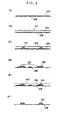
- step S40 in Fig. 7 the non-coagulated ink not associated with the dots and the micro-droplets of the second oily substance are scraped from the positive electrode surface.
- the most part of the non-coagulated ink 110 is removed from the surface 12B by scraping the surface 12B with the first squeegee 34 and the dots 120 of coagulated ink are brought into a sufficiently uncovered state.
- the unscraped non-coagulated ink 110 and a portion of dots of the coagulated ink scraped by the squeegee remain, as the fogging ink 130, on the surface 12B.
- This state is shown in Fig. 3(D).
- the non-coagulated ink 110 removed by the first squeegee 34 is collected to be circulated as described above.
- the first oily substance is applied onto the surface of the positive electrode.
- the first oily substance 140 is continuously supplied onto the surface 12B of the positive electrode from the oily substance supply port 38.
- the first oily substance 140 may be of the same type as or the different type from the second oily substance.
- oleic acid which is the same as that used for the second oily substance is used for the first oily substance.
- Fig. 3(E) shows the state in which the first oily substance is supplied onto the surface 12B.
Description
Claims (14)
- An electrocoagulation printing method comprising the steps of:(a) providing a positive electrode (12) made of an electrolytically inert metal and having a continuous passivated surface as a positive electrode active surface (12B) moving along a predetermined path;(b) forming on said positive electrode active surface (12B) a plurality of dots of coagulated ink representative of a desired image by electrocoagulation of electrocoagulation printing ink (110);(c) bringing a substrate (80) into contact with said dots of coagulated ink to cause transfer of the dots of coagulated ink from said positive electrode active surface (12B) onto the substrate (80), characterised by between steps (b) and (c);(d) applying a first oily substance (140) onto said positive electrode active surface (12B) to mix the first oily substance (140) with fogging ink (130) in a non-image portion;(e) removing the fogging ink (130) mixed with the first oily substance (140) from said non-image portion of said positive electrode active surface (12B) without altering said dots of coagulated ink.
- An electrocoagulation printing method to which the electrocoagulation printing method according to Claim 1 is applied,
wherein a plurality of printing stages is defined which is arranged at predetermined locations along said path and each use different electrocoagulation printing ink (110), steps (b), (d), (e) and (c) are repeated several times, thereby several images are reproduced at respective transfer part on said substrate (80). - An electrocoagulation printing method according to Claim 1 or to Claim 2, characterised in that said first oily substance (140) is selected from the group consisting of unsaturated fatty acids and unsaturated vegetable oils.
- An electrocoagulation printing method according to Claim 1 or to Claim 2, characterised in that said step (b) includes the steps of:(i) providing a plurality of electrolytically inert negative electrodes electrically insulated from one another and arranged in rectilinear alignment to define a series of corresponding negative electrode active surfaces disposed in a plane parallel to the longitudinal axis of said positive electrode (12) and spaced from the positive electrode active surface (12B) by a constant predetermined gap, said negative electrodes being spaced from one another by a distance at least equal to said electrode gap;(ii) coating the positive electrode active surface (12B) with a second oily substance to form on said surface (12B) micro-droplets of the second oily substance;(iii) filing said electrode gap with said electrocoagulation printing ink (110);(iv) electrically energizing selected ones of said negative electrodes to cause selectively coagulation of the electrocoagulation printing ink (110) and adherence of coagulated ink onto the positive electrode active surface (12B) coated with the second oily substance opposite the electrode active surfaces of said energized negative electrodes while said positive electrode (12) is rotating, thereby forming dots of said coagulated ink; and(v) removing any remaining non-coagulated ink from said positive electrode active surface (12B).
- An electrocoagulation printing method according to Claim 4, characterised in that said step (b) (ii) includes the steps of: providing first and second distribution rollers (22, 24) extending parallel to said positive electrode (12) and each having a peripheral coating comprising an oxide ceramic material; applying said second oily substance onto the ceramic coating of said first distribution roller (22) to form on the surface thereof a film of said second oily substance uniformly covering the surface of said ceramic coating, said film of second oily substance at least partially breaking down into micro-droplets having substantially uniform size and distribution; transferring the at least partially broken film from said first distribution roller (22) to said second distribution roller (24) so as to cause said film to substantially completely break on the ceramic coating of said second distribution roller (24) into said micro-droplets having substantially uniform size and distribution; and transferring said micro-droplets from the ceramic coating of said second distribution roller (24) onto said positive electrode active surface (12B).
- An electrocoagulation printing method according to any one of Claims 1, 2 and 4, characterised in that a mixture of fogging ink removed from said positive electrode active surface (12B) and the first oily substance (140) is collected, the first oily substance (140) is separated from the collected mixture, and the separated first oily substance (140) is applied again onto said positive electrode active surface (12B).
- An electrocoagulation printing method according to Claim 6, characterised in that said first oily substance (140) is separated from said mixture by admixing water with said mixture to form an aqueous phase containing said removed fogging ink (130) and an oily phase containing said first oily substance (140), separating said oily phase from said aqueous phase, filtering the separated oily phase to remove therefrom suspended solids, and recovering the filtered oily phase for reapplication onto said positive electrode active surface (12B).
- An electrocoagulation printing apparatus (10), comprising:a positive electrode (12) made of an electrolytically inert metal and having a continuous passiavated surface as a positive electrode active surface (12B) moving along a predetermined path;an ink feeding part (32) which supplies electrocoagulation printing ink (110) onto said positive electrode active surface (12B) ;a negative electrode for reproducing on said positive electrode active surface (12B) dots of coagulated ink by electrocoagulation; anda transfer part (70) which brings a substrate (80) into contact with the dots of coagulated ink to cause transfer of the dots of coagulated ink from said positive electrode active surface (12B) to said substrate (80); characterised bya fogging ink removing portion (40) which supplies a first oily substance (140) onto said a non-image portion of said positive electrode active surface (12B) and removes fogging ink (130) mixed with the first oily substance (140) from said non-image portion of said positive electrode active surface (12B) without altering said dots of coagulated ink.
- An electrocoagulation printing apparatus (10) according to Claim 8, characterised by a coating part (14) for coating the positive electrode active surface (12B) with a second oily substance.
- An electrocoagulation printing apparatus (10) according to Claim 8, characterised by circulation means (44, 46, 52, 54) in which a mixture of fogging ink (130) removed from said positive electrode active surface (12B) and the first oily substance (140) is collected, the first oily substance (140) is separated from the collected mixture, and the separated first oily substance (140) is applied again onto said positive electrode active surface (12B).
- An electrocoagulation printing system comprising:characterised by a plurality of fogging ink removing portions which supply a first oily substance (140) onto a non-image portion of said said positive electrode active surface (12B) and remove fogging ink (130) mixed with the first oily substance (140) from said non-image portion of said positive electrode active surface (12B) without altering said dots of coagulated ink.at least one positive electrode (12, 12') made of an electrolytically inert metal and having a continuous passivated surface as a positive electrode active surface (12B) moving along a predetermined path;a plurality of ink feeding parts (32) which supply electrocoagulation printing ink (110) onto said positive electrode active surface (12B) ;a plurality of negative electrodes for reproducing on said positive electrode active surface (12B) dots of coagulated ink by electrocoagulation; anda plurality of transfer parts (70) which bring a substrate (80) into contact with the dots of coagulated ink to cause transfer of the dots of coagulated ink from said positive electrode active surface (12B) to said substrate (80);
- An electrocoagulation printing system according to Claim 11, comprising a plurality of printing stations (10), characterised in that each of said printing stations (10) has the positive electrode (12), one of said plurality of ink feeding parts (32), one of said plurality of negative electrodes, one of said plurality of fogging ink removing portions (40) and one of said plurality of transfer parts (70).
- An electrocoagulation printing system according to Claim 11, comprising the positive electrode (12'), and a plurality of printing stations (88), characterised in that each printing station (88) has one of said plurality of ink feeding parts (32), one of said plurality of negative electrodes, one of said plurality of fogging ink removing portions (40), and one of said plurality of transfer parts (70), and further characterised in that said plurality of printing stations (88) are disposed along the path of the positive electrode (12').
- An electrocoagulation printing system according to any of Claims 11 to 13, characterised by a coating part (14) for coating the positive electrode active surface (12B) with a second oily substance.
Applications Claiming Priority (3)
| Application Number | Priority Date | Filing Date | Title |
|---|---|---|---|
| CA 2169669 CA2169669C (en) | 1996-02-16 | 1996-02-16 | Method of preventing formation of undesirable background on electrocoagulation printed images |
| CA2169669 | 1996-02-16 | ||
| PCT/JP1997/000418 WO1997030379A1 (en) | 1996-02-16 | 1997-02-17 | Electrical coagulation printing method and electrical coagulation printing apparatus |
Publications (3)
| Publication Number | Publication Date |
|---|---|
| EP0822462A1 EP0822462A1 (en) | 1998-02-04 |
| EP0822462A4 EP0822462A4 (en) | 1999-05-06 |
| EP0822462B1 true EP0822462B1 (en) | 2003-05-02 |
Family
ID=4157588
Family Applications (1)
| Application Number | Title | Priority Date | Filing Date |
|---|---|---|---|
| EP97902708A Expired - Lifetime EP0822462B1 (en) | 1996-02-16 | 1997-02-17 | Electrical coagulation printing method and electrical coagulation printing apparatus |
Country Status (5)
| Country | Link |
|---|---|
| EP (1) | EP0822462B1 (en) |
| AU (1) | AU1672997A (en) |
| CA (1) | CA2169669C (en) |
| DE (1) | DE69721409T2 (en) |
| WO (1) | WO1997030379A1 (en) |
Families Citing this family (2)
| Publication number | Priority date | Publication date | Assignee | Title |
|---|---|---|---|---|
| CA2224339C (en) * | 1997-12-10 | 2003-02-11 | Pierre Castegnier | Printing head system for use in an electrocoagulation printing apparatus |
| JP3067771B1 (en) | 1999-07-12 | 2000-07-24 | ヤマハ株式会社 | Printing equipment |
Family Cites Families (2)
| Publication number | Priority date | Publication date | Assignee | Title |
|---|---|---|---|---|
| CA1279603C (en) * | 1986-02-20 | 1991-01-29 | Adrien Castegnier | Monochromic and polychromic printing of an image reproduced by electro-coagulation of a colloid |
| CA1334017C (en) * | 1989-04-12 | 1995-01-17 | Adrien Castegnier | High-speed electrocoagulation printing method and apparatus |
-
1996
- 1996-02-16 CA CA 2169669 patent/CA2169669C/en not_active Expired - Fee Related
-
1997
- 1997-02-17 DE DE69721409T patent/DE69721409T2/en not_active Expired - Fee Related
- 1997-02-17 WO PCT/JP1997/000418 patent/WO1997030379A1/en active IP Right Grant
- 1997-02-17 EP EP97902708A patent/EP0822462B1/en not_active Expired - Lifetime
- 1997-02-17 AU AU16729/97A patent/AU1672997A/en not_active Abandoned
Also Published As
| Publication number | Publication date |
|---|---|
| CA2169669A1 (en) | 1997-08-17 |
| DE69721409D1 (en) | 2003-06-05 |
| EP0822462A4 (en) | 1999-05-06 |
| CA2169669C (en) | 2001-01-23 |
| WO1997030379A1 (en) | 1997-08-21 |
| DE69721409T2 (en) | 2003-11-13 |
| EP0822462A1 (en) | 1998-02-04 |
| AU1672997A (en) | 1997-09-02 |
Similar Documents
| Publication | Publication Date | Title |
|---|---|---|
| US5727462A (en) | Multicolor dynamic printing method and apparatus | |
| CA1334017C (en) | High-speed electrocoagulation printing method and apparatus | |
| US5908541A (en) | Multicolor electrocoagulation printing method and apparatus | |
| EP0822462B1 (en) | Electrical coagulation printing method and electrical coagulation printing apparatus | |
| US5693206A (en) | Electrocoagulation printing apparatus | |
| US5690803A (en) | Method of enhancing transfer of coagulated colloid onto a substrate during electrocoagulation printing | |
| EP0899094B1 (en) | Multicolor electrocoagulation printing method and apparatus | |
| US5690801A (en) | Method of rendering an electrocoagulation printed image water-fast | |
| US5681436A (en) | Method of preventing formation of undesirable background on electrocoagulation printed images | |
| CA2214606C (en) | Method of preventing anode abrasion during electrocoagulation printing | |
| US6551481B2 (en) | Electrocoagulation printing method and apparatus providing color juxtaposition | |
| US5690802A (en) | Method of increasing coagulation efficiency during electrocoagulation printing | |
| CA2156978C (en) | Multicolor dynamic printing method and apparatus | |
| US5863402A (en) | Method of preventing anode abrasion during electrocoagulation printing | |
| CA2355458C (en) | Electrocoagulation printing method and apparatus providing color juxtaposition | |
| CA2194130C (en) | Method of enhancing transfer of coagulated colloid onto a substrate during electrocoagulation printing | |
| CA2194128C (en) | Method of increasing coagulation efficiency during electrocoagulation printing | |
| CA2194129C (en) | Method of rendering an electrocoagulation printed image water-fast | |
| EP1285748A2 (en) | Electrocoagulation printing method and apparatus providing color juxtaposition | |
| CA2282188C (en) | Intermittent electrocoagulation printing method and apparatus | |
| EP1348546A2 (en) | Electrocoagulation printing method providing an image having enhanced optical density | |
| CA2334265C (en) | Electrocoagulation printing method and apparatus providing enhanced image resolution | |
| JP2002086788A (en) | Method and apparatus for intermittent electric solidification printing | |
| US20010025794A1 (en) | Electrocoagulation printing method and apparatus providing enhanced image resolution | |
| AU713694B2 (en) | Electro-coagulation printing apparatus |
Legal Events
| Date | Code | Title | Description |
|---|---|---|---|
| PUAI | Public reference made under article 153(3) epc to a published international application that has entered the european phase |
Free format text: ORIGINAL CODE: 0009012 |
|
| AK | Designated contracting states |
Kind code of ref document: A1 Designated state(s): DE FR GB IT |
|
| 17P | Request for examination filed |
Effective date: 19971022 |
|
| A4 | Supplementary search report drawn up and despatched |
Effective date: 19990318 |
|
| AK | Designated contracting states |
Kind code of ref document: A4 Designated state(s): DE FR GB IT |
|
| 17Q | First examination report despatched |
Effective date: 20011001 |
|
| GRAG | Despatch of communication of intention to grant |
Free format text: ORIGINAL CODE: EPIDOS AGRA |
|
| RTI1 | Title (correction) |
Free format text: ELECTRICAL COAGULATION PRINTING METHOD AND ELECTRICAL COAGULATION PRINTING APPARATUS |
|
| GRAG | Despatch of communication of intention to grant |
Free format text: ORIGINAL CODE: EPIDOS AGRA |
|
| GRAH | Despatch of communication of intention to grant a patent |
Free format text: ORIGINAL CODE: EPIDOS IGRA |
|
| GRAH | Despatch of communication of intention to grant a patent |
Free format text: ORIGINAL CODE: EPIDOS IGRA |
|
| GRAA | (expected) grant |
Free format text: ORIGINAL CODE: 0009210 |
|
| AK | Designated contracting states |
Designated state(s): DE FR GB IT |
|
| REG | Reference to a national code |
Ref country code: GB Ref legal event code: FG4D |
|
| REF | Corresponds to: |
Ref document number: 69721409 Country of ref document: DE Date of ref document: 20030605 Kind code of ref document: P |
|
| PGFP | Annual fee paid to national office [announced via postgrant information from national office to epo] |
Ref country code: FR Payment date: 20040210 Year of fee payment: 8 |
|
| PGFP | Annual fee paid to national office [announced via postgrant information from national office to epo] |
Ref country code: GB Payment date: 20040211 Year of fee payment: 8 |
|
| PGFP | Annual fee paid to national office [announced via postgrant information from national office to epo] |
Ref country code: DE Payment date: 20040226 Year of fee payment: 8 |
|
| ET | Fr: translation filed | ||
| PLBE | No opposition filed within time limit |
Free format text: ORIGINAL CODE: 0009261 |
|
| STAA | Information on the status of an ep patent application or granted ep patent |
Free format text: STATUS: NO OPPOSITION FILED WITHIN TIME LIMIT |
|
| 26N | No opposition filed |
Effective date: 20040203 |
|
| PG25 | Lapsed in a contracting state [announced via postgrant information from national office to epo] |
Ref country code: IT Free format text: LAPSE BECAUSE OF NON-PAYMENT OF DUE FEES Effective date: 20050217 Ref country code: GB Free format text: LAPSE BECAUSE OF NON-PAYMENT OF DUE FEES Effective date: 20050217 |
|
| PG25 | Lapsed in a contracting state [announced via postgrant information from national office to epo] |
Ref country code: DE Free format text: LAPSE BECAUSE OF NON-PAYMENT OF DUE FEES Effective date: 20050901 |
|
| GBPC | Gb: european patent ceased through non-payment of renewal fee |
Effective date: 20050217 |
|
| PG25 | Lapsed in a contracting state [announced via postgrant information from national office to epo] |
Ref country code: FR Free format text: LAPSE BECAUSE OF NON-PAYMENT OF DUE FEES Effective date: 20051031 |
|
| REG | Reference to a national code |
Ref country code: FR Ref legal event code: ST Effective date: 20051031 |