EP0822346A1 - Stock mit änderlicher Länge und Verriegelungsvorrichtung dafür - Google Patents
Stock mit änderlicher Länge und Verriegelungsvorrichtung dafür Download PDFInfo
- Publication number
- EP0822346A1 EP0822346A1 EP97110927A EP97110927A EP0822346A1 EP 0822346 A1 EP0822346 A1 EP 0822346A1 EP 97110927 A EP97110927 A EP 97110927A EP 97110927 A EP97110927 A EP 97110927A EP 0822346 A1 EP0822346 A1 EP 0822346A1
- Authority
- EP
- European Patent Office
- Prior art keywords
- lever
- cam
- cylindrical body
- stick
- locking device
- Prior art date
- Legal status (The legal status is an assumption and is not a legal conclusion. Google has not performed a legal analysis and makes no representation as to the accuracy of the status listed.)
- Granted
Links
- 230000007935 neutral effect Effects 0.000 claims description 4
- 230000001105 regulatory effect Effects 0.000 description 2
- 238000004140 cleaning Methods 0.000 description 1
- 230000008878 coupling Effects 0.000 description 1
- 238000010168 coupling process Methods 0.000 description 1
- 238000005859 coupling reaction Methods 0.000 description 1
- 230000001419 dependent effect Effects 0.000 description 1
- 239000000463 material Substances 0.000 description 1
- 230000000399 orthopedic effect Effects 0.000 description 1
- 239000007787 solid Substances 0.000 description 1
Images

Classifications
-
- F—MECHANICAL ENGINEERING; LIGHTING; HEATING; WEAPONS; BLASTING
- F16—ENGINEERING ELEMENTS AND UNITS; GENERAL MEASURES FOR PRODUCING AND MAINTAINING EFFECTIVE FUNCTIONING OF MACHINES OR INSTALLATIONS; THERMAL INSULATION IN GENERAL
- F16B—DEVICES FOR FASTENING OR SECURING CONSTRUCTIONAL ELEMENTS OR MACHINE PARTS TOGETHER, e.g. NAILS, BOLTS, CIRCLIPS, CLAMPS, CLIPS OR WEDGES; JOINTS OR JOINTING
- F16B2/00—Friction-grip releasable fastenings
- F16B2/02—Clamps, i.e. with gripping action effected by positive means other than the inherent resistance to deformation of the material of the fastening
- F16B2/18—Clamps, i.e. with gripping action effected by positive means other than the inherent resistance to deformation of the material of the fastening using cams, levers, eccentrics, or toggles
- F16B2/185—Clamps, i.e. with gripping action effected by positive means other than the inherent resistance to deformation of the material of the fastening using cams, levers, eccentrics, or toggles using levers
-
- F—MECHANICAL ENGINEERING; LIGHTING; HEATING; WEAPONS; BLASTING
- F16—ENGINEERING ELEMENTS AND UNITS; GENERAL MEASURES FOR PRODUCING AND MAINTAINING EFFECTIVE FUNCTIONING OF MACHINES OR INSTALLATIONS; THERMAL INSULATION IN GENERAL
- F16B—DEVICES FOR FASTENING OR SECURING CONSTRUCTIONAL ELEMENTS OR MACHINE PARTS TOGETHER, e.g. NAILS, BOLTS, CIRCLIPS, CLAMPS, CLIPS OR WEDGES; JOINTS OR JOINTING
- F16B7/00—Connections of rods or tubes, e.g. of non-circular section, mutually, including resilient connections
- F16B7/10—Telescoping systems
- F16B7/14—Telescoping systems locking in intermediate non-discrete positions
- F16B7/1418—Telescoping systems locking in intermediate non-discrete positions with a clamping collar or two split clamping rings tightened by a screw or a cammed latch member
Definitions
- the present invention relates to a stick of adjustable variable length and a relative locking device.
- ski sticks whose length can be adjusted to adapt to the height of the user.
- the most widely used is that of providing for telescopic sliding of two tubes one inside the other, and locking by means of a special clamp that is tightened on the outer tube.
- EP-A-641 578 describes such a clamp which is particularly advantageous in that it has a somewhat flattened profile and has no projecting parts when the clamp is in the closed position.
- This clamp substantially comprises a hollow cylindrical body, open on one side, where the cam end of a closing lever is hinged.
- the object of the invention is to improve the locking device according to the above mentioned patent EP-A-641 578, eliminating the drawbacks described above and allowing easy opening of the device, with minimum effort.
- Another object of the invention is to allow improved closure of the locking device.
- the clamp operating cam is freed from the maneuvering lever, allowing a certain angular play between lever and cam.
- the sides of the operating lever can be provided with two teeth which enter the corresponding seats provided in the body of the clamp, causing a click which indicates perfect closure of the device.
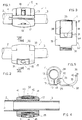
- a partial view of a ski stick 1 comprising an upper tubular element 2, bearing at its distal end a grip (not shown) and a lower tubular element 3, ending in a point and a disk (not shown).
- the lower tubular element 3 has a slightly smaller diameter than the upper element 2, so that it can slide telescopically inside the latter (see Fig. 4).
- a longitudinal slit 4 is provided, which allows its diameter to be narrowed following external pressure, and thus clamped on the tubular element 3, so that axial sliding is prevented.
- the locking device according to the invention is situated at the join between the two tubes 2 and 3.
- the device 10 comprises a hollow cylindrical body 11, which is disposed around the terminal section 9 of the tubular element 2 and has an inner annular ridge 12, against which the end of the tube 2 abuts (see in particular Figure 4).
- the hollow cylindrical body 11 has a longitudinal cut or slot 13, delimited by two opposite longitudinal projections 14,15 in said body 11.
- Coaxial through holes able to house a pivot 16 are provided in said projecting parts 14, 15 (see in particular Figure 7).
- the pivot 16 is essentially composed of a screw 17, which screws into a nut 18, so as to be able to regulate the length of the pivot.
- the screw 17 has a head 19, which abuts on the outer side of the projection 15, whilst the nut 18 is housed completely in the corresponding hole 20 provided in the projection 14, which has a greater diameter than the hole 21 provided in the projection 15 for passage of the screw 17.
- a hole 22 is also provided, for fixing of the cam and the maneuvering lever of the device, as will be described better below.
- a cam surface 30 is provided, shaped in a slightly concave manner (see in particular Figure 5), so that when a force is applied against said surface 30, the projection 14 is pushed against the projection 15 through the elasticity of the material making up the body 11, normally plastic, thereby causing closure of the clamp and thus clamping of the tubes 2,3 without any possibility of reciprocal sliding.
- Said closing or opening force on the cam surface 30 is exerted by means of a cam 31, operated by a lever 32, constituting a separate element from the cam 31.
- the lever 32 and the cam 31 are assembled together with each other and with said pivot 16, by means of a pin 25, which is inserted in the aligned holes provided in said elements, involving the entire length of the device.
- the lever 32 has a curved course and such a shape as to enter a corresponding seat provided in the cylindrical body, fitting it perfectly without projecting from its outer profile.
- the lever 32 has a base portion 33 having the same width as the cylindrical body 11, and able to position itself, when closed, in a corresponding seat 34 provided in the body 11, by means of a reduction in the thickness of the corresponding section, along the whole length of the body.
- the remaining part 35 of the lever 32, up to the free end, has a smaller width than the length of the body 11, and seats in a corresponding rectangular seat 36 with a corresponding width, provided in the body 11 and delimited by respective opposite vertical walls 37, 38.
- the free end 39 of the lever 32 is bent slightly outward and is the only part projecting from the profile of the clamp, to facilitate gripping during opening, as will be better described below.
- a pair of side teeth 40 are provided which engage in corresponding hollows 41 provided in said opposite side walls 37, 38 of the cylindrical body 11, causing a click of the lever during closing.
- the base portion 33 of the lever 32 is fork-shaped, so as to enclose between its prongs 44 the cam 31, which in turn has a central cavity 45, inside which is housed the nut 18 of the pivot 16.
- the shape and assembly of the cam 31 and the lever 32 are such as to allow the latter a certain free angle of rotation, about 30° (see Figure 8), in which the movement of the lever is not transferred to the cam.
- Provision of this angular play between the lever 32 and the cam 31 offers the considerable advantage, when the lever is in the closed position, of being able to raise the lever sufficiently, without exerting the least force, from position A to position B shown with a broken line in Figure 8.
- position B the lever can be gripped much more effectively to move it from the open position C, making the can 31 rotate, and thus opening the locking device.
- the angle of rotation between positions B and C is indicated as 95° in Figure 8.
- Freeing the lever 32 from the cam 31 has made it possible to achieve a further advantage with respect to conventional systems in which the lever and the cam were made in a single body.
- the locking device according to the invention makes it possible to adjust the closing pressure and/or to adapt to tubes of slightly different diameters, regulating the pre-closing force of the cylindrical body 11 by regulating engagement of the screw 17 in the nut 18.
- the ski stick can be divided into more than two tubular elements that can slide telescopically one inside the other, providing a locking device according to the invention to join adjacent tubular elements.
- the ski stick comprises three tubular elements and two locking devices.
- the invention protects the locking device in itself, applied to clamping of any two tubular telescopic elements, forming, for example, an orthopedic stick, a stick for window cleaning, or other.
Landscapes
- Engineering & Computer Science (AREA)
- General Engineering & Computer Science (AREA)
- Mechanical Engineering (AREA)
- Mutual Connection Of Rods And Tubes (AREA)
- Rehabilitation Tools (AREA)
- Surgical Instruments (AREA)
- Mechanical Pencils And Projecting And Retracting Systems Therefor, And Multi-System Writing Instruments (AREA)
- Fittings On The Vehicle Exterior For Carrying Loads, And Devices For Holding Or Mounting Articles (AREA)
- Footwear And Its Accessory, Manufacturing Method And Apparatuses (AREA)
Applications Claiming Priority (2)
| Application Number | Priority Date | Filing Date | Title |
|---|---|---|---|
| ITMI961695 | 1996-08-02 | ||
| IT96MI001695A IT1283677B1 (it) | 1996-08-02 | 1996-08-02 | Bastone da sci a lunghezza regolabile e relativo dispositivo di bloccaggio |
Publications (2)
| Publication Number | Publication Date |
|---|---|
| EP0822346A1 true EP0822346A1 (de) | 1998-02-04 |
| EP0822346B1 EP0822346B1 (de) | 2001-05-23 |
Family
ID=11374765
Family Applications (1)
| Application Number | Title | Priority Date | Filing Date |
|---|---|---|---|
| EP97110927A Expired - Lifetime EP0822346B1 (de) | 1996-08-02 | 1997-07-02 | Stock mit änderlicher Länge und Verriegelungsvorrichtung dafür |
Country Status (4)
| Country | Link |
|---|---|
| EP (1) | EP0822346B1 (de) |
| AT (1) | ATE201486T1 (de) |
| DE (1) | DE69704910T2 (de) |
| IT (1) | IT1283677B1 (de) |
Cited By (13)
| Publication number | Priority date | Publication date | Assignee | Title |
|---|---|---|---|---|
| EP1351012A1 (de) * | 2002-04-02 | 2003-10-08 | Alliance Technology Group, Inc. | Tragvorrichtung für Arbeitsleuchte |
| KR20040063185A (ko) * | 2003-01-06 | 2004-07-14 | 아주공업주식회사 | 장형부재 취급용 밴드 |
| EP1741937A1 (de) * | 2005-07-05 | 2007-01-10 | Christian Patron | Klemmvorrichtung für die Ausrüstung eines Schwimmbeckens |
| WO2009003297A1 (de) * | 2007-07-03 | 2009-01-08 | Lekisport Ag | Längenverstellbarer stock und klemmvorrichtung dafür |
| CH700317A1 (de) * | 2009-01-29 | 2010-07-30 | Lekisport Ag | Klemmvorrichtung und längenverstellbarer Stock mit einer solchen Klemmvorrichtung. |
| WO2010085905A1 (de) * | 2009-01-29 | 2010-08-05 | Lekisport Ag | Längenverstellbarer stock und klemmvorrichtung dafür |
| EP2213192A3 (de) * | 2009-01-30 | 2011-03-02 | Salewa Sport AG | Sportstock |
| WO2013020861A1 (en) | 2011-08-05 | 2013-02-14 | Gipron Giuseppe Pronzati S.R.L. | Telescopic stick foldable in two portions |
| CN104074849A (zh) * | 2013-03-28 | 2014-10-01 | 加德纳波勒系统有限公司 | 快速释放夹持组件及包括该夹持组件的杆组件 |
| WO2018026463A1 (en) * | 2016-08-05 | 2018-02-08 | Fiskars Brands, Inc. | Clamping mechanism for an adjustable length tool |
| US11246262B2 (en) | 2012-10-15 | 2022-02-15 | Chervon (Hk) Limited | Operation safety assembly for a lawncare apparatus |
| US11606900B2 (en) | 2012-10-15 | 2023-03-21 | Chervon (Hk) Limited | Gardening tool |
| US11638397B2 (en) | 2020-02-10 | 2023-05-02 | Techtronic Cordless Gp | Control assembly coupled to handle of an implement |
Families Citing this family (2)
| Publication number | Priority date | Publication date | Assignee | Title |
|---|---|---|---|---|
| DE10040129B4 (de) * | 2000-08-17 | 2014-11-06 | Valeo Auto-Electric Wischer Und Motoren Gmbh | Wischvorrichtung |
| DE202010006677U1 (de) | 2010-05-11 | 2011-09-02 | Salewa Sport Ag | Sportstock mit verschiebbarem Stellelement |
Citations (3)
| Publication number | Priority date | Publication date | Assignee | Title |
|---|---|---|---|---|
| DE8428699U1 (de) * | 1984-09-28 | 1986-04-03 | Schlimme, Wolfram, Dr.Ing. Dipl.-Ing. Dipl.-Wirtsch.-Ing., 8000 München | Beleuchtungseinrichtung zur Anbringung an über ein Fahrzeug hinausragenden, rohrförmigen Körpern |
| WO1992000834A1 (de) * | 1990-07-05 | 1992-01-23 | Robert Bosch Gmbh | Spannvorrichtung zum festspannen einer schutzhaube am spannhals einer handwerkzeugmaschine |
| EP0641578A1 (de) * | 1993-09-01 | 1995-03-08 | GIPRON - GIUSEPPE PRONZATI S.p.A. | Längsverschiebbarer Skistock und Schelle |
-
1996
- 1996-08-02 IT IT96MI001695A patent/IT1283677B1/it active IP Right Grant
-
1997
- 1997-07-02 DE DE69704910T patent/DE69704910T2/de not_active Expired - Lifetime
- 1997-07-02 EP EP97110927A patent/EP0822346B1/de not_active Expired - Lifetime
- 1997-07-02 AT AT97110927T patent/ATE201486T1/de active
Patent Citations (3)
| Publication number | Priority date | Publication date | Assignee | Title |
|---|---|---|---|---|
| DE8428699U1 (de) * | 1984-09-28 | 1986-04-03 | Schlimme, Wolfram, Dr.Ing. Dipl.-Ing. Dipl.-Wirtsch.-Ing., 8000 München | Beleuchtungseinrichtung zur Anbringung an über ein Fahrzeug hinausragenden, rohrförmigen Körpern |
| WO1992000834A1 (de) * | 1990-07-05 | 1992-01-23 | Robert Bosch Gmbh | Spannvorrichtung zum festspannen einer schutzhaube am spannhals einer handwerkzeugmaschine |
| EP0641578A1 (de) * | 1993-09-01 | 1995-03-08 | GIPRON - GIUSEPPE PRONZATI S.p.A. | Längsverschiebbarer Skistock und Schelle |
Cited By (19)
| Publication number | Priority date | Publication date | Assignee | Title |
|---|---|---|---|---|
| EP1351012A1 (de) * | 2002-04-02 | 2003-10-08 | Alliance Technology Group, Inc. | Tragvorrichtung für Arbeitsleuchte |
| KR20040063185A (ko) * | 2003-01-06 | 2004-07-14 | 아주공업주식회사 | 장형부재 취급용 밴드 |
| EP1741937A1 (de) * | 2005-07-05 | 2007-01-10 | Christian Patron | Klemmvorrichtung für die Ausrüstung eines Schwimmbeckens |
| WO2009003297A1 (de) * | 2007-07-03 | 2009-01-08 | Lekisport Ag | Längenverstellbarer stock und klemmvorrichtung dafür |
| RU2488328C2 (ru) * | 2009-01-29 | 2013-07-27 | Лекиспорт Аг | Регулируемая по длине палка для ходьбы и зажимное устройство для нее |
| CH700317A1 (de) * | 2009-01-29 | 2010-07-30 | Lekisport Ag | Klemmvorrichtung und längenverstellbarer Stock mit einer solchen Klemmvorrichtung. |
| US8496018B2 (en) | 2009-01-29 | 2013-07-30 | Lekisport Ag | Length-adjustable pole and clamping apparatus therefor |
| US8807152B2 (en) | 2009-01-29 | 2014-08-19 | Lekisport Ag | Length-adjustable pole and clamping apparatus therefor |
| WO2010085905A1 (de) * | 2009-01-29 | 2010-08-05 | Lekisport Ag | Längenverstellbarer stock und klemmvorrichtung dafür |
| EP2213192A3 (de) * | 2009-01-30 | 2011-03-02 | Salewa Sport AG | Sportstock |
| WO2013020861A1 (en) | 2011-08-05 | 2013-02-14 | Gipron Giuseppe Pronzati S.R.L. | Telescopic stick foldable in two portions |
| US9198488B2 (en) | 2011-08-05 | 2015-12-01 | Gipron Giuseppe Pronzati S.R.L. | Telescopic stick foldable in two portions |
| US11246262B2 (en) | 2012-10-15 | 2022-02-15 | Chervon (Hk) Limited | Operation safety assembly for a lawncare apparatus |
| US11606900B2 (en) | 2012-10-15 | 2023-03-21 | Chervon (Hk) Limited | Gardening tool |
| US11252867B2 (en) | 2012-10-15 | 2022-02-22 | Chervon (Hk) Limited | Safety assembly for a lawncare apparatus |
| CN104074849A (zh) * | 2013-03-28 | 2014-10-01 | 加德纳波勒系统有限公司 | 快速释放夹持组件及包括该夹持组件的杆组件 |
| EP2784335A1 (de) * | 2013-03-28 | 2014-10-01 | Gardiner Pole Systems Ltd | Klemmenanordnung |
| WO2018026463A1 (en) * | 2016-08-05 | 2018-02-08 | Fiskars Brands, Inc. | Clamping mechanism for an adjustable length tool |
| US11638397B2 (en) | 2020-02-10 | 2023-05-02 | Techtronic Cordless Gp | Control assembly coupled to handle of an implement |
Also Published As
| Publication number | Publication date |
|---|---|
| DE69704910T2 (de) | 2001-11-15 |
| DE69704910D1 (de) | 2001-06-28 |
| EP0822346B1 (de) | 2001-05-23 |
| IT1283677B1 (it) | 1998-04-23 |
| ITMI961695A1 (it) | 1998-02-02 |
| ATE201486T1 (de) | 2001-06-15 |
| ITMI961695A0 (de) | 1996-08-02 |
Similar Documents
| Publication | Publication Date | Title |
|---|---|---|
| EP0822346B1 (de) | Stock mit änderlicher Länge und Verriegelungsvorrichtung dafür | |
| EP1358409B1 (de) | Hebelbetätigter verschluss mit teleskopstange | |
| CA2079224A1 (en) | Surgical instrument | |
| US4547092A (en) | Accessory clamp for medical table | |
| US4858608A (en) | Applicator | |
| US5851189A (en) | Torque device for angioplasty guidewire | |
| US5315741A (en) | Snap fastener for securing shoe laces | |
| JP2656216B2 (ja) | 長さ調節自在スキー棒および円筒状シャフトのクランプ | |
| US5154449A (en) | Extensible rod | |
| RU2488328C2 (ru) | Регулируемая по длине палка для ходьбы и зажимное устройство для нее | |
| US5791805A (en) | Locking device for telescoping elements | |
| EP1157921B1 (de) | Integrierter Drehgriffschalter | |
| JPH10148291A (ja) | 二つの円管部材を接続する継手装置 | |
| JPH05184501A (ja) | 真空掃除機用伸縮式延長管 | |
| US5842371A (en) | Wire crimper having adjustment mechanism for adjusting pitch of the jaw mouth | |
| US6626951B1 (en) | Locking device intended as a fastening element for a prosthesis | |
| US5039146A (en) | Tubular latch housing | |
| EP1469242A1 (de) | Handgriffe für Ventile | |
| EP0750289A2 (de) | Verschlussvorrichtung für Saiteninstrumente | |
| US20170014600A1 (en) | Steerable catheter handle with slide lock | |
| CA2511383A1 (en) | Locking device for telescoping rods | |
| US20070262291A1 (en) | Device for the actuation of each of several mechanisms through a respective rope | |
| JPH0246327Y2 (de) | ||
| FR2564395A1 (fr) | Enrouleur de ceinture de securite | |
| JPH076219Y2 (ja) | 給水栓の操作レバー |
Legal Events
| Date | Code | Title | Description |
|---|---|---|---|
| PUAI | Public reference made under article 153(3) epc to a published international application that has entered the european phase |
Free format text: ORIGINAL CODE: 0009012 |
|
| AK | Designated contracting states |
Kind code of ref document: A1 Designated state(s): AT CH DE ES FI FR GB IT LI NL SE |
|
| AX | Request for extension of the european patent |
Free format text: AL;LT;LV;RO;SI |
|
| 17P | Request for examination filed |
Effective date: 19980522 |
|
| AKX | Designation fees paid |
Free format text: AT CH DE ES FI FR GB IT LI NL SE |
|
| AXX | Extension fees paid |
Free format text: SI PAYMENT 980522 |
|
| RBV | Designated contracting states (corrected) |
Designated state(s): AT CH DE ES FI FR GB IT LI NL SE |
|
| 17Q | First examination report despatched |
Effective date: 19990120 |
|
| GRAG | Despatch of communication of intention to grant |
Free format text: ORIGINAL CODE: EPIDOS AGRA |
|
| GRAG | Despatch of communication of intention to grant |
Free format text: ORIGINAL CODE: EPIDOS AGRA |
|
| GRAH | Despatch of communication of intention to grant a patent |
Free format text: ORIGINAL CODE: EPIDOS IGRA |
|
| GRAH | Despatch of communication of intention to grant a patent |
Free format text: ORIGINAL CODE: EPIDOS IGRA |
|
| GRAA | (expected) grant |
Free format text: ORIGINAL CODE: 0009210 |
|
| AK | Designated contracting states |
Kind code of ref document: B1 Designated state(s): AT CH DE ES FI FR GB IT LI NL SE |
|
| AX | Request for extension of the european patent |
Free format text: SI PAYMENT 19980522 |
|
| PG25 | Lapsed in a contracting state [announced via postgrant information from national office to epo] |
Ref country code: NL Free format text: LAPSE BECAUSE OF FAILURE TO SUBMIT A TRANSLATION OF THE DESCRIPTION OR TO PAY THE FEE WITHIN THE PRESCRIBED TIME-LIMIT Effective date: 20010523 Ref country code: LI Free format text: LAPSE BECAUSE OF FAILURE TO SUBMIT A TRANSLATION OF THE DESCRIPTION OR TO PAY THE FEE WITHIN THE PRESCRIBED TIME-LIMIT Effective date: 20010523 Ref country code: FR Free format text: LAPSE BECAUSE OF FAILURE TO SUBMIT A TRANSLATION OF THE DESCRIPTION OR TO PAY THE FEE WITHIN THE PRESCRIBED TIME-LIMIT Effective date: 20010523 Ref country code: FI Free format text: LAPSE BECAUSE OF FAILURE TO SUBMIT A TRANSLATION OF THE DESCRIPTION OR TO PAY THE FEE WITHIN THE PRESCRIBED TIME-LIMIT Effective date: 20010523 Ref country code: CH Free format text: LAPSE BECAUSE OF FAILURE TO SUBMIT A TRANSLATION OF THE DESCRIPTION OR TO PAY THE FEE WITHIN THE PRESCRIBED TIME-LIMIT Effective date: 20010523 |
|
| REF | Corresponds to: |
Ref document number: 201486 Country of ref document: AT Date of ref document: 20010615 Kind code of ref document: T |
|
| REG | Reference to a national code |
Ref country code: CH Ref legal event code: EP |
|
| ITF | It: translation for a ep patent filed |
Owner name: RACHELI & C. S.R.L. |
|
| REF | Corresponds to: |
Ref document number: 69704910 Country of ref document: DE Date of ref document: 20010628 |
|
| PG25 | Lapsed in a contracting state [announced via postgrant information from national office to epo] |
Ref country code: SE Free format text: LAPSE BECAUSE OF FAILURE TO SUBMIT A TRANSLATION OF THE DESCRIPTION OR TO PAY THE FEE WITHIN THE PRESCRIBED TIME-LIMIT Effective date: 20010823 Ref country code: GB Free format text: LAPSE BECAUSE OF NON-PAYMENT OF DUE FEES Effective date: 20010823 |
|
| NLV1 | Nl: lapsed or annulled due to failure to fulfill the requirements of art. 29p and 29m of the patents act | ||
| PG25 | Lapsed in a contracting state [announced via postgrant information from national office to epo] |
Ref country code: ES Free format text: LAPSE BECAUSE OF FAILURE TO SUBMIT A TRANSLATION OF THE DESCRIPTION OR TO PAY THE FEE WITHIN THE PRESCRIBED TIME-LIMIT Effective date: 20011130 |
|
| REG | Reference to a national code |
Ref country code: CH Ref legal event code: PL |
|
| EN | Fr: translation not filed | ||
| PLBE | No opposition filed within time limit |
Free format text: ORIGINAL CODE: 0009261 |
|
| STAA | Information on the status of an ep patent application or granted ep patent |
Free format text: STATUS: NO OPPOSITION FILED WITHIN TIME LIMIT |
|
| GBPC | Gb: european patent ceased through non-payment of renewal fee |
Effective date: 20010823 |
|
| 26N | No opposition filed | ||
| PGFP | Annual fee paid to national office [announced via postgrant information from national office to epo] |
Ref country code: DE Payment date: 20120817 Year of fee payment: 16 Ref country code: IT Payment date: 20120730 Year of fee payment: 16 |
|
| PGFP | Annual fee paid to national office [announced via postgrant information from national office to epo] |
Ref country code: AT Payment date: 20120801 Year of fee payment: 16 |
|
| REG | Reference to a national code |
Ref country code: AT Ref legal event code: MM01 Ref document number: 201486 Country of ref document: AT Kind code of ref document: T Effective date: 20130702 |
|
| PG25 | Lapsed in a contracting state [announced via postgrant information from national office to epo] |
Ref country code: DE Free format text: LAPSE BECAUSE OF NON-PAYMENT OF DUE FEES Effective date: 20140201 |
|
| REG | Reference to a national code |
Ref country code: DE Ref legal event code: R119 Ref document number: 69704910 Country of ref document: DE Effective date: 20140201 |
|
| PG25 | Lapsed in a contracting state [announced via postgrant information from national office to epo] |
Ref country code: AT Free format text: LAPSE BECAUSE OF NON-PAYMENT OF DUE FEES Effective date: 20130702 Ref country code: IT Free format text: LAPSE BECAUSE OF NON-PAYMENT OF DUE FEES Effective date: 20130702 |