EP0821822B1 - Avertisseur sonore piezo-electrique, notamment pour l'equipement de vehicules - Google Patents
Avertisseur sonore piezo-electrique, notamment pour l'equipement de vehicules Download PDFInfo
- Publication number
- EP0821822B1 EP0821822B1 EP96911020A EP96911020A EP0821822B1 EP 0821822 B1 EP0821822 B1 EP 0821822B1 EP 96911020 A EP96911020 A EP 96911020A EP 96911020 A EP96911020 A EP 96911020A EP 0821822 B1 EP0821822 B1 EP 0821822B1
- Authority
- EP
- European Patent Office
- Prior art keywords
- membrane
- piezoelectric
- ceramic
- horn
- horn according
- Prior art date
- Legal status (The legal status is an assumption and is not a legal conclusion. Google has not performed a legal analysis and makes no representation as to the accuracy of the status listed.)
- Expired - Lifetime
Links
- 239000012528 membrane Substances 0.000 claims abstract description 108
- 239000000919 ceramic Substances 0.000 claims abstract description 45
- 239000002184 metal Substances 0.000 claims abstract description 16
- 239000003351 stiffener Substances 0.000 claims abstract description 12
- 239000000725 suspension Substances 0.000 claims description 6
- 230000006978 adaptation Effects 0.000 claims description 5
- 241000723353 Chrysanthemum Species 0.000 claims description 4
- 235000005633 Chrysanthemum balsamita Nutrition 0.000 claims description 4
- 230000006835 compression Effects 0.000 claims description 4
- 238000007906 compression Methods 0.000 claims description 4
- 238000007599 discharging Methods 0.000 claims 1
- 230000000694 effects Effects 0.000 description 10
- 239000013078 crystal Substances 0.000 description 8
- 239000008188 pellet Substances 0.000 description 4
- 230000008901 benefit Effects 0.000 description 3
- 239000000463 material Substances 0.000 description 3
- 239000004033 plastic Substances 0.000 description 3
- 229920003023 plastic Polymers 0.000 description 3
- 230000010287 polarization Effects 0.000 description 3
- 241000283153 Cetacea Species 0.000 description 2
- 230000005284 excitation Effects 0.000 description 2
- 238000000465 moulding Methods 0.000 description 2
- 230000002441 reversible effect Effects 0.000 description 2
- 229920002799 BoPET Polymers 0.000 description 1
- 229910001369 Brass Inorganic materials 0.000 description 1
- 241000019217 Chrysocale Species 0.000 description 1
- 206010010219 Compulsions Diseases 0.000 description 1
- 206010011878 Deafness Diseases 0.000 description 1
- 239000005041 Mylar™ Substances 0.000 description 1
- 241000722921 Tulipa gesneriana Species 0.000 description 1
- 230000009471 action Effects 0.000 description 1
- 230000001154 acute effect Effects 0.000 description 1
- 238000007792 addition Methods 0.000 description 1
- 238000004026 adhesive bonding Methods 0.000 description 1
- 230000003042 antagnostic effect Effects 0.000 description 1
- 230000033228 biological regulation Effects 0.000 description 1
- 239000010951 brass Substances 0.000 description 1
- 230000008859 change Effects 0.000 description 1
- 239000004020 conductor Substances 0.000 description 1
- 238000010276 construction Methods 0.000 description 1
- 238000010411 cooking Methods 0.000 description 1
- 239000002178 crystalline material Substances 0.000 description 1
- 238000006073 displacement reaction Methods 0.000 description 1
- 230000005684 electric field Effects 0.000 description 1
- 229920002457 flexible plastic Polymers 0.000 description 1
- 238000002955 isolation Methods 0.000 description 1
- 238000000034 method Methods 0.000 description 1
- 238000012986 modification Methods 0.000 description 1
- 230000004048 modification Effects 0.000 description 1
- 229920000915 polyvinyl chloride Polymers 0.000 description 1
- 239000004800 polyvinyl chloride Substances 0.000 description 1
- 239000010453 quartz Substances 0.000 description 1
- 230000009467 reduction Effects 0.000 description 1
- 230000004044 response Effects 0.000 description 1
- VYPSYNLAJGMNEJ-UHFFFAOYSA-N silicon dioxide Inorganic materials O=[Si]=O VYPSYNLAJGMNEJ-UHFFFAOYSA-N 0.000 description 1
- 238000005245 sintering Methods 0.000 description 1
- 238000005476 soldering Methods 0.000 description 1
- 238000001228 spectrum Methods 0.000 description 1
- 239000004753 textile Substances 0.000 description 1
Images


Classifications
-
- G—PHYSICS
- G10—MUSICAL INSTRUMENTS; ACOUSTICS
- G10K—SOUND-PRODUCING DEVICES; METHODS OR DEVICES FOR PROTECTING AGAINST, OR FOR DAMPING, NOISE OR OTHER ACOUSTIC WAVES IN GENERAL; ACOUSTICS NOT OTHERWISE PROVIDED FOR
- G10K9/00—Devices in which sound is produced by vibrating a diaphragm or analogous element, e.g. fog horns, vehicle hooters or buzzers
- G10K9/12—Devices in which sound is produced by vibrating a diaphragm or analogous element, e.g. fog horns, vehicle hooters or buzzers electrically operated
Definitions
- the present invention relates to audible warning devices, in particular for equipment for motor vehicles, and it concerns more particularly a piezoelectric horn.
- Audible warning devices currently motor vehicles use the vibration of a membrane under the action of a system electromagnetic. These horns electromagnetic, which are universally used, have the disadvantage of being heavy not negligible (around 250g) and present a significant average electrical consumption (approximately 4 to 6 Amps at a supply voltage of 12 V).
- the object of the present invention is to remedy the above mentioned drawbacks of electromagnetic horns and it offers, for this purpose, the realization of an alarm piezoelectric that is to say an audible warning using the vibration of a piezoelectric membrane.
- effect piezoelectric by which electric charges appear on the faces of certain crystals (quartz in particular) when these are subject to constraints mechanical. Since these crystals are generally insulating, the charges that appear on their faces give electrical voltages, which can be very high, and these electrical voltages are collected by metal electrodes on the faces of crystals.
- the piezoelectric effect is characteristic ordered structures of matter (crystals), but mono-crystalline materials are rare and few convenient to implement.
- ceramics with a crystal structure also lend themselves to the implementation of effects piezoelectric by prior orientation molecules constituting the ceramic. This orientation is obtained by applying for a few seconds a high bias electric field on ceramic, causing the molecules to align within ceramics. When the field is deleted electric polarization, molecular orientation subsists and gives rise to a piezoelectric phenomenon identical to that observed in single crystals.
- the polarized ceramics are much more convenient to use than crystals, especially effect they are obtained in the form desired by sintering at high temperature and cooking at more than 1000 ° C.
- the membrane piezoelectric is mounted in a suitable support, this mounting device participates so significant to the sound emission of the membrane in modifying the resonance frequencies of the membrane and more generally the frequency response of the device.
- Piezoelectric membranes currently available on the market are only used for low noise applications. These applications mainly concern telephony, Low level sound reproduction in devices portable, and also the noisemakers for switchgear industrial and instrumentation: in particular car noise makers (reporting a forgotten headlights, a door that remained open or an engine fault).
- the only applications with noise level higher than 100 dBA concern either acute frequency generators (1800 at 3600 Hz for car alarms), i.e. narrow frequency band and power applications limited (105 dB at 1000 Hz for back-up alarms for trucks and vehicles).
- the sound level measured at 2m from the alarm in free field (or in a deaf room) must be between 105 dBA and 118 dBA and the level sound of this alarm, once mounted on the vehicle, must be 93 dBA 7 meters in front of the vehicle.
- the subject of the present invention is a new design and use of an element piezoelectric sound allowing the realization of a buzzer that fully meets the conditions laid down, and which presents in relation to traditional electromagnetic horns the advantage of a significant reduction in weight and its electrical consumption.
- the piezoelectric membrane is a membrane with a diameter included between 60 and 100mm, presenting a resonance peak main in a frequency zone between 350 and 500 Hz and a large amplitude of vibration, and its suspension is designed to allow a large travel for minimum stress and deformation on ceramic.
- the piezoelectric membrane used according to the invention should vibrate sweep a certain volume during its vibration.
- the membrane will have to bend, without however reaching the minimum radius of curvature below which the ceramic breaks.
- the suspension device of this membrane should be designed according to the invention for obtain, from a ceramic having a radius of given limit curvature, the largest volume scan possible. To this end, the suspension of the membrane must be free and not embedded.
- the diameter of the membrane according to the invention must be substantially higher than that of the membranes currently on the market (50mm) which is too small to allow reach both 120 decibels and 400 Hz required. We are therefore led to increase the diameter of the membranes, which does not necessarily lead to increasing the diameter of the ceramic pellets.
- the invention proposes to realize the piezoelectric membrane under the shape of a large diameter metal membrane (by example of the order of 9cm) equipped in the center with a smaller ceramic tablet (around from 3 to 5cm for example).
- the part located at right of the ceramic undergoes a deformation in cap spherical, while the rest of the membrane tends to dampen the deformation by taking a reverse curvature at that of the spherical cap.
- the rest of the membrane should takes the form of a truncated cone tangent to the cap spherical.
- the piezoelectric membrane either in its external part (not covered by ceramic) both rigid in the radial direction and flexible in the diametrical direction, from so as to be able to deform only "in a tulip" or well “in umbrella".
- the part center of the membrane on which the ceramic must retain its elastic properties isotropic.
- such a deformation is obtained by starting from a flexible membrane on which grafting rigid elements arranged along the spokes, like the whales of an umbrella.
- These elements can be reported items (like whales umbrella), or even folds or ribs arranged along the rays of the membrane.
- These elements are arranged in a ring around the periphery of the membrane, from the outer edge to the limit of the area covered by the ceramic, so that retain the faculty in the central part of the membrane to deform into a "spherical cap". Between the stiffening elements, the membrane must be very flexible.
- An advantageous embodiment of a such membrane according to the invention comprises a membrane molded rubber on which a membrane is stuck metallic daisy shaped. At the center of this daisy-shaped membrane is pasted of piezoelectric ceramic. In the axis of each daisy petal can be arranged a stiffener, such as a fold, which slightly encroaches on the part central so that during the deformation of this central part, these stiffeners are positioned according to a tangent to the spherical part.
- the outer shape of the so-called membrane rubber is advantageously shaped so as to create waves intended to give a maximum of flexibility in fixing the membrane both in flexion that in extension.
- the waves thus created also the effect of distributing the stresses and therefore the rubber fatigue over a larger area, leading to a longer lifespan.
- the "daisy" membrane can be made in two parts, a homogeneous central part in lined metal a crown of stiffeners not necessarily metallic and can therefore be obtained by molding plastic material.
- the rubber part of the membrane could also be glued to the same side of the membrane metallic than the piezoelectric pellet.
- the membrane rubber being obtained by molding, it would be easy to spare the space available for this purpose.
- This contact system allows also to connect cheaply for a second small electrode located on the pad of ceramic.
- This second electrode constitutes with the ceramic underlying a piezoelectric sensor providing an electrical voltage which varies with the displacement of the membrane.
- This voltage is used in the electronic control circuit to control the control frequency so that it automatically tunes to the resonant frequency of the membrane. In this way, without adjustment, a maximum sound level.
- Yet another role of the rubber part of the membrane according to the invention is to ensure the waterproofness of the horn, an appropriate form being for this purpose arranged at the end of the waves of the membrane.
- the invention plans to use as an acoustic adaptation element a resonator of Helmholtz with cavity or an exponential pavilion rolled up or folded, the choice being made so as to obtain, depending on the diameter of the membrane selected, the best compromise between sound quality and clutter.
- the control circuit preferably the push-in type, is designed to provide high control voltage, around one hundred volts.
- a variety of control modes are then possible, ranging from control by voltage sinusoidal through a transformer to high voltage brief pulse systems produced by capacitive switching.
- the membrane it is however necessary to adapt the membrane to the signal delivered by the control circuit, and this adaptation can be carried out as follows: when the control circuit chosen delivers a symmetrical waveform (alternating voltage or even at zero mean value), a membrane will advantageously be used, the central part of which supports the ceramic, is planar. Indeed the symmetrical waveforms will stress the membrane alternately in one direction then in the other.
- a symmetrical waveform alternating voltage or even at zero mean value
- control circuits delivering electrical pulses of a single polarity.
- the membrane is stressed only in one direction and, if a flat membrane is used, the amplitude of allowed travel for a given radius of curvature will be half of that obtained by a waveform symmetrical.
- advantage to choose a form membrane already deformed at rest so that only after polarization, and in the absence of solicitation electric, the radius of curvature of the ceramic is close to the minimum allowable. Electric impulses will then be applied so as to cause an antagonistic deformation compared to the initial deformation. So, for a radius of given limit curvature of ceramic it is possible to obtain, with control pulses from a single polarity. the same amplitude of vibration as with symmetrical pulses.
- a ceramic disc which is stuck on a metal plate 2 having the shape of a rectangle with rounded corners.
- the metal of the plate 2 is a brass or chrysocale with good elasticity.
- the relationship between the length and width of the plate 2 is included between 1.1 and 1.5.
- An annular structure 3 made of light metal, notched crown shape, rigidly attached (by soldering or gluing) at the periphery of the plate 2).
- the external part of the crown 3 has sixteen fingers which are arranged radially and are distributed evenly around the edge. These fingers are provided, the along their axis, a boss 4 produced by stamping. These bosses 4 play the role of stiffeners by preventing the fingers from deforming.
- the annular structure 3 could also be made of rigid plastic, the bosses 4 then being replaced by edges.
- the whole of the plate 2 and structure 3 can be made in one single metal part by cutting and cold stamping.
- the entire membrane comprising the ceramic 1, metallic puddle 2 and crown stiffener 3, is then fixed on a membrane of molded rubber 5.
- This membrane 5 is shaped circular, for greater assembly convenience alarms, has a thick exterior 6 of rectangular section forming mounting joint.
- the membrane 5 also includes a part softened 7 in the form of waves, intended to allow the free movement of the central part of the device.
- the central part of the membrane 5 includes molded reserves allowing the housing of the ceramic 1 and plate 2 if applicable.
- a ceramic with two electrodes is used allowing, at lower cost, enslavement automatic excitation frequency.
- FIG. 3 there is shown a circuit of control for a piezoelectric horn according to the invention.
- This control circuit is designed to be as economical as possible. It includes a generator modified high flyback type.
- the transistor T is blocked and the energy stored in the coil L is transferred, passing through a diode D in series with the coil L, in the capacity C formed by the piezoelectric membrane. Diode D then prevents ability to discharge in turn into the coil L.
- the second electrode E of the membrane provides the integrated circuit G with a feedback voltage which controls the frequency of control compulsions it provides on the frequency giving the maximum amplitude to the movement of the membrane.
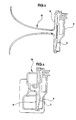
- FIG 4 we have schematized the construction, which in itself is classic, of the horn using the membrane shown in Figures 1 and 2.
- the membrane 5 is mounted between a housing 8 and a plate 9, both made of plastic material.
- the space 10 between the membrane 5 and the plate 9 determines a compression chamber whose central event 11 communicates, as we will see in Figures 5 and 6, with the center of a pavilion acoustic.
- the control circuit (which has been described in detail in figure 3) is mounted on a printed plate 12 which includes all of the electronic components shown in 13.
- the connection with the outside is made by a connector 14, molded in the housing 8, of which the slats 15 are mounted directly on the circuit printed.
- connection of the electrodes of the membrane is made by means of metallic ribbons, molded into the membrane 5, which have been described more high. These ribbons come out of the membrane at a protuberance 16 which makes it possible to establish contact by simple pressure during assembly.
- the horn is completed by a flag, which includes a cross-section part used to acoustic tuning and an exponential part.
- Pavilion 17 may be straight, in the case truck alarms, as shown in Figure 5, but the pavilion will preferably be of the type rolled up like on conventional horns as well that it has been represented at 18 in FIG. 6.
Landscapes
- Physics & Mathematics (AREA)
- Engineering & Computer Science (AREA)
- Acoustics & Sound (AREA)
- Multimedia (AREA)
- Piezo-Electric Transducers For Audible Bands (AREA)
- Emergency Alarm Devices (AREA)
- Ultra Sonic Daignosis Equipment (AREA)
- Fittings On The Vehicle Exterior For Carrying Loads, And Devices For Holding Or Mounting Articles (AREA)
- Burglar Alarm Systems (AREA)
Applications Claiming Priority (3)
| Application Number | Priority Date | Filing Date | Title |
|---|---|---|---|
| FR9504006A FR2732805B1 (fr) | 1995-04-05 | 1995-04-05 | Avertisseur sonore piezo-electrique, notamment pour l'equipement de vehicules |
| FR9504006 | 1995-04-05 | ||
| PCT/FR1996/000498 WO1996031869A1 (fr) | 1995-04-05 | 1996-04-03 | Avertisseur sonore piezo-electrique, notamment pour l'equipement de vehicules |
Publications (2)
| Publication Number | Publication Date |
|---|---|
| EP0821822A1 EP0821822A1 (fr) | 1998-02-04 |
| EP0821822B1 true EP0821822B1 (fr) | 1999-10-20 |
Family
ID=9477762
Family Applications (1)
| Application Number | Title | Priority Date | Filing Date |
|---|---|---|---|
| EP96911020A Expired - Lifetime EP0821822B1 (fr) | 1995-04-05 | 1996-04-03 | Avertisseur sonore piezo-electrique, notamment pour l'equipement de vehicules |
Country Status (10)
| Country | Link |
|---|---|
| US (1) | US6166624A (da) |
| EP (1) | EP0821822B1 (da) |
| AT (1) | ATE185921T1 (da) |
| AU (1) | AU5403096A (da) |
| DE (1) | DE69604797T2 (da) |
| DK (1) | DK0821822T3 (da) |
| ES (1) | ES2141494T3 (da) |
| FR (1) | FR2732805B1 (da) |
| PT (1) | PT821822E (da) |
| WO (1) | WO1996031869A1 (da) |
Families Citing this family (4)
| Publication number | Priority date | Publication date | Assignee | Title |
|---|---|---|---|---|
| DE10148303B4 (de) | 2001-09-29 | 2006-12-14 | Dbt Gmbh | Verwendung eines Warntongebers |
| DE50106265D1 (de) * | 2001-12-01 | 2005-06-23 | Siemens Building Tech Ag | Akustischer Alarmgeber für einen Gefahrenmelder |
| JP4048203B2 (ja) * | 2003-02-26 | 2008-02-20 | 株式会社ユーエスシー | 圧電発電装置 |
| WO2009154658A1 (en) * | 2008-02-22 | 2009-12-23 | Piezolnnovations | Ultrasonic torsional mode and longitudinal-torsional mode transducer systems |
Family Cites Families (4)
| Publication number | Priority date | Publication date | Assignee | Title |
|---|---|---|---|---|
| GB249826A (en) * | 1925-03-30 | 1927-05-05 | North East Electric Co | Improvement in electric horns |
| JPS59193497A (ja) * | 1983-04-18 | 1984-11-02 | 富士電気化学株式会社 | 圧電ブザ− |
| JPS60134700A (ja) * | 1983-12-23 | 1985-07-17 | Nippon Denso Co Ltd | 発音装置 |
| JPS6372381A (ja) * | 1986-09-17 | 1988-04-02 | 株式会社日本自動車部品総合研究所 | 容量性負荷の駆動方法 |
-
1995
- 1995-04-05 FR FR9504006A patent/FR2732805B1/fr not_active Expired - Fee Related
-
1996
- 1996-04-03 PT PT96911020T patent/PT821822E/pt unknown
- 1996-04-03 AT AT96911020T patent/ATE185921T1/de not_active IP Right Cessation
- 1996-04-03 WO PCT/FR1996/000498 patent/WO1996031869A1/fr not_active Ceased
- 1996-04-03 DK DK96911020T patent/DK0821822T3/da active
- 1996-04-03 AU AU54030/96A patent/AU5403096A/en not_active Abandoned
- 1996-04-03 DE DE69604797T patent/DE69604797T2/de not_active Expired - Fee Related
- 1996-04-03 US US08/930,869 patent/US6166624A/en not_active Expired - Fee Related
- 1996-04-03 EP EP96911020A patent/EP0821822B1/fr not_active Expired - Lifetime
- 1996-04-03 ES ES96911020T patent/ES2141494T3/es not_active Expired - Lifetime
Also Published As
| Publication number | Publication date |
|---|---|
| PT821822E (pt) | 2000-04-28 |
| WO1996031869A1 (fr) | 1996-10-10 |
| DE69604797T2 (de) | 2000-11-16 |
| ES2141494T3 (es) | 2000-03-16 |
| ATE185921T1 (de) | 1999-11-15 |
| US6166624A (en) | 2000-12-26 |
| AU5403096A (en) | 1996-10-23 |
| DE69604797D1 (de) | 1999-11-25 |
| DK0821822T3 (da) | 2000-06-19 |
| EP0821822A1 (fr) | 1998-02-04 |
| FR2732805A1 (fr) | 1996-10-11 |
| FR2732805B1 (fr) | 1997-06-20 |
Similar Documents
| Publication | Publication Date | Title |
|---|---|---|
| EP0230336B1 (fr) | Dispositif opto-électronique pour montage en surface | |
| EP0587032A1 (fr) | Transducteur capacitif intégré | |
| FR2511570A1 (fr) | Transducteur electroacoustique a polymere piezoelectrique | |
| FR2889402A1 (fr) | Capteur a ultrasons | |
| EP1415059A1 (fr) | Poignee d'ouvrant pour vehicule automobile | |
| FR2463562A1 (fr) | Haut-parleur piezo-electrique | |
| FR2493984A1 (fr) | Transducteur de pression a element vibrant | |
| EP0821822B1 (fr) | Avertisseur sonore piezo-electrique, notamment pour l'equipement de vehicules | |
| EP0177383A1 (fr) | Transducteur omnidirectionnel d'ondes élastiques à large bande passante et procédé de fabrication | |
| EP1519453B1 (fr) | Instrument électronique portable comprenant au moins un terminal d'entrée et/ou sortie adapté pour établir une communication avec une unité électronique logée à l'intérieur dudit instrument | |
| FR2632898A3 (fr) | Dispositif de signalisation pour pneumatique | |
| FR2792577A1 (fr) | Vehicule automobile comportant un systeme de controle de la pression des pneumatiques | |
| EP3006119B1 (fr) | Dispositif électronique de génération d'un avertissement sonore ou d'une musique | |
| CH708212B1 (fr) | Microgénérateur, en particulier pour montre-bracelet. | |
| FR2926760A1 (fr) | Agencement pour l'evacuation d'eau sur une surface optique de vehicule automobile. | |
| FR2544530A1 (fr) | Ronfleur piezoelectrique | |
| EP0403378B1 (fr) | Haut-parleur omnidirectionnel à membrane sphérique utilisant un ruban bilame magnétostrictif | |
| EP0694824B1 (fr) | Pièce d'horlogerie comportant un transducteur électro-acoustique | |
| EP0303547A1 (fr) | Transducteur omnidirectionnel d'ondes élastiques à large bande passante | |
| EP3339981B1 (fr) | Montre munie d'un poussoir thermoelectrique | |
| EP1128239B1 (fr) | Objet portatif tel que, notamment, une pièce d'horlogerie, comprenant un transducteur piézo-électrique pour l'introduction manuelle de données | |
| FR2551573A1 (fr) | Sirene electronique | |
| FR2711284A1 (fr) | Appareil d'entraînement et appareil photographique le comportant. | |
| FR2681262A1 (fr) | Source electromagnetique acoustique d'impulsions de pression. | |
| FR2567704A1 (fr) | Haut-parleur, en particulier pour sirene d'alarme |
Legal Events
| Date | Code | Title | Description |
|---|---|---|---|
| PUAI | Public reference made under article 153(3) epc to a published international application that has entered the european phase |
Free format text: ORIGINAL CODE: 0009012 |
|
| 17P | Request for examination filed |
Effective date: 19971003 |
|
| AK | Designated contracting states |
Kind code of ref document: A1 Designated state(s): AT DE DK ES FI FR GB IE IT NL PT SE |
|
| GRAG | Despatch of communication of intention to grant |
Free format text: ORIGINAL CODE: EPIDOS AGRA |
|
| 17Q | First examination report despatched |
Effective date: 19981222 |
|
| GRAG | Despatch of communication of intention to grant |
Free format text: ORIGINAL CODE: EPIDOS AGRA |
|
| GRAH | Despatch of communication of intention to grant a patent |
Free format text: ORIGINAL CODE: EPIDOS IGRA |
|
| GRAH | Despatch of communication of intention to grant a patent |
Free format text: ORIGINAL CODE: EPIDOS IGRA |
|
| GRAA | (expected) grant |
Free format text: ORIGINAL CODE: 0009210 |
|
| AK | Designated contracting states |
Kind code of ref document: B1 Designated state(s): AT DE DK ES FI FR GB IE IT NL PT SE |
|
| PG25 | Lapsed in a contracting state [announced via postgrant information from national office to epo] |
Ref country code: FR Free format text: THE PATENT HAS BEEN ANNULLED BY A DECISION OF A NATIONAL AUTHORITY Effective date: 19991020 |
|
| REF | Corresponds to: |
Ref document number: 185921 Country of ref document: AT Date of ref document: 19991115 Kind code of ref document: T |
|
| REF | Corresponds to: |
Ref document number: 69604797 Country of ref document: DE Date of ref document: 19991125 |
|
| RAP2 | Party data changed (patent owner data changed or rights of a patent transferred) |
Owner name: SOCIETE DE COMPOSANTS ELECTRIQUES |
|
| ITF | It: translation for a ep patent filed | ||
| REG | Reference to a national code |
Ref country code: IE Ref legal event code: FG4D Free format text: FRENCH |
|
| NLT2 | Nl: modifications (of names), taken from the european patent patent bulletin |
Owner name: SOCIETE DE COMPOSANTS ELECTRIQUES |
|
| GBT | Gb: translation of ep patent filed (gb section 77(6)(a)/1977) |
Effective date: 20000120 |
|
| REG | Reference to a national code |
Ref country code: ES Ref legal event code: FG2A Ref document number: 2141494 Country of ref document: ES Kind code of ref document: T3 |
|
| REG | Reference to a national code |
Ref country code: PT Ref legal event code: SC4A Free format text: AVAILABILITY OF NATIONAL TRANSLATION Effective date: 20000117 |
|
| REG | Reference to a national code |
Ref country code: DK Ref legal event code: T3 |
|
| PLBE | No opposition filed within time limit |
Free format text: ORIGINAL CODE: 0009261 |
|
| STAA | Information on the status of an ep patent application or granted ep patent |
Free format text: STATUS: NO OPPOSITION FILED WITHIN TIME LIMIT |
|
| 26N | No opposition filed | ||
| PGFP | Annual fee paid to national office [announced via postgrant information from national office to epo] |
Ref country code: GB Payment date: 20010412 Year of fee payment: 6 |
|
| PGFP | Annual fee paid to national office [announced via postgrant information from national office to epo] |
Ref country code: SE Payment date: 20010417 Year of fee payment: 6 Ref country code: PT Payment date: 20010417 Year of fee payment: 6 Ref country code: NL Payment date: 20010417 Year of fee payment: 6 Ref country code: DK Payment date: 20010417 Year of fee payment: 6 |
|
| PGFP | Annual fee paid to national office [announced via postgrant information from national office to epo] |
Ref country code: IE Payment date: 20010419 Year of fee payment: 6 Ref country code: FI Payment date: 20010419 Year of fee payment: 6 Ref country code: DE Payment date: 20010419 Year of fee payment: 6 |
|
| PGFP | Annual fee paid to national office [announced via postgrant information from national office to epo] |
Ref country code: ES Payment date: 20010427 Year of fee payment: 6 Ref country code: AT Payment date: 20010427 Year of fee payment: 6 |
|
| REG | Reference to a national code |
Ref country code: GB Ref legal event code: IF02 |
|
| REG | Reference to a national code |
Ref country code: FR Ref legal event code: ST |
|
| PG25 | Lapsed in a contracting state [announced via postgrant information from national office to epo] |
Ref country code: IE Free format text: LAPSE BECAUSE OF NON-PAYMENT OF DUE FEES Effective date: 20020403 Ref country code: GB Free format text: LAPSE BECAUSE OF NON-PAYMENT OF DUE FEES Effective date: 20020403 Ref country code: FI Free format text: LAPSE BECAUSE OF NON-PAYMENT OF DUE FEES Effective date: 20020403 Ref country code: AT Free format text: LAPSE BECAUSE OF NON-PAYMENT OF DUE FEES Effective date: 20020403 |
|
| PG25 | Lapsed in a contracting state [announced via postgrant information from national office to epo] |
Ref country code: SE Free format text: LAPSE BECAUSE OF NON-PAYMENT OF DUE FEES Effective date: 20020404 Ref country code: ES Free format text: LAPSE BECAUSE OF NON-PAYMENT OF DUE FEES Effective date: 20020404 |
|
| PG25 | Lapsed in a contracting state [announced via postgrant information from national office to epo] |
Ref country code: DK Free format text: LAPSE BECAUSE OF NON-PAYMENT OF DUE FEES Effective date: 20020430 |
|
| PG25 | Lapsed in a contracting state [announced via postgrant information from national office to epo] |
Ref country code: PT Free format text: LAPSE BECAUSE OF NON-PAYMENT OF DUE FEES Effective date: 20021031 |
|
| PG25 | Lapsed in a contracting state [announced via postgrant information from national office to epo] |
Ref country code: NL Free format text: LAPSE BECAUSE OF NON-PAYMENT OF DUE FEES Effective date: 20021101 Ref country code: DE Free format text: LAPSE BECAUSE OF NON-PAYMENT OF DUE FEES Effective date: 20021101 |
|
| EUG | Se: european patent has lapsed |
Ref document number: 96911020.4 |
|
| GBPC | Gb: european patent ceased through non-payment of renewal fee |
Effective date: 20020403 |
|
| REG | Reference to a national code |
Ref country code: DK Ref legal event code: EBP |
|
| NLV4 | Nl: lapsed or anulled due to non-payment of the annual fee |
Effective date: 20021101 |
|
| REG | Reference to a national code |
Ref country code: PT Ref legal event code: MM4A Free format text: LAPSE DUE TO NON-PAYMENT OF FEES Effective date: 20021031 |
|
| REG | Reference to a national code |
Ref country code: IE Ref legal event code: MM4A |
|
| REG | Reference to a national code |
Ref country code: ES Ref legal event code: FD2A Effective date: 20030514 |
|
| PG25 | Lapsed in a contracting state [announced via postgrant information from national office to epo] |
Ref country code: IT Free format text: LAPSE BECAUSE OF NON-PAYMENT OF DUE FEES;WARNING: LAPSES OF ITALIAN PATENTS WITH EFFECTIVE DATE BEFORE 2007 MAY HAVE OCCURRED AT ANY TIME BEFORE 2007. THE CORRECT EFFECTIVE DATE MAY BE DIFFERENT FROM THE ONE RECORDED. Effective date: 20050403 |