EP0820688A2 - Dispositif pour le contrÔle au minimum d'un actionneur d'un véhicule utilitaire - Google Patents
Dispositif pour le contrÔle au minimum d'un actionneur d'un véhicule utilitaire Download PDFInfo
- Publication number
- EP0820688A2 EP0820688A2 EP97110720A EP97110720A EP0820688A2 EP 0820688 A2 EP0820688 A2 EP 0820688A2 EP 97110720 A EP97110720 A EP 97110720A EP 97110720 A EP97110720 A EP 97110720A EP 0820688 A2 EP0820688 A2 EP 0820688A2
- Authority
- EP
- European Patent Office
- Prior art keywords
- control unit
- control
- functions
- unit
- data
- Prior art date
- Legal status (The legal status is an assumption and is not a legal conclusion. Google has not performed a legal analysis and makes no representation as to the accuracy of the status listed.)
- Granted
Links
Images
Classifications
-
- A—HUMAN NECESSITIES
- A01—AGRICULTURE; FORESTRY; ANIMAL HUSBANDRY; HUNTING; TRAPPING; FISHING
- A01B—SOIL WORKING IN AGRICULTURE OR FORESTRY; PARTS, DETAILS, OR ACCESSORIES OF AGRICULTURAL MACHINES OR IMPLEMENTS, IN GENERAL
- A01B63/00—Lifting or adjusting devices or arrangements for agricultural machines or implements
- A01B63/02—Lifting or adjusting devices or arrangements for agricultural machines or implements for implements mounted on tractors
- A01B63/10—Lifting or adjusting devices or arrangements for agricultural machines or implements for implements mounted on tractors operated by hydraulic or pneumatic means
Definitions
- the invention relates to a device for control at least one actuator of a work vehicle, in particular an agricultural tractor, according to the preamble of the claim 1.
- DE 34 40 625 C2 describes a control device at least one actuator of a work vehicle known with an electronic control unit that the Automatic vehicle lifting maneuvers controls or lowering the actuators.
- the control unit has a series of timers that are sequential Adjusting the actuators in a fixed predetermined Cause time sequence.
- a disadvantage of this device is that the application of the device to the Turning is limited and that the operator during driving in the work vehicle has no influence on the Sequence of actuating functions can take.
- DE 44 28 824 A1 describes a control device known at least one actuator, which is a control unit includes a number of control functions that run according to a fixed program. By pressing an automatic switch, the control unit opens Ready switched. With actuation of another operating switch the program is started, so that afterwards a sequence of control functions by the actuators be processed. For example, after Operating the control switch the hoist from the working position brought into the transport position and at the same time the differential lock is switched off. The adjustment follows further actuators until the work vehicle in the Excavated state has passed. This device too has the disadvantage that the operator has no influence can take on the sequence of control functions.
- the invention enables an operator to be able to is shifted by operating any control element Setting functions automatically in a desired order to be carried out.
- the operator only needs in a first workflow as the input process Manually operate the sequence of controls selected by him then after activation by actuating an automatic element expires automatically. That way one adapted to the individual needs of the operator Automation of control processes implemented. This can advantageously meet the requirements of field processing depending on the climatic conditions by additional loading or control of a Actuator are taken into account.
- control unit an operating unit assigned to at least one Input switch to start the input process, at least an automatic switch for calling up or starting the automatic process and at least one reset switch to clear of the automatic process. So that several automatic processes are stored and can be called up, the control unit shows several input, corresponding to each other, Automatic and reset switch on.
- control unit is a Assigned display unit that the to be stored or stored control functions visualized and thus the Operator control over the running control functions gives.
- control unit is integrated with the operating unit and the display unit in a common structural unit.
- structural unit is designed to be detachable from the cockpit of the work vehicle, so that after the plug-and-play technology "can be used with appropriate programming in several work vehicles.
- the control unit is advantageously connected via a bus system to the operating elements permanently installed in the work vehicle, so that these can be actuated in the input sequence in a way that the operator is used to.
- the operator also about the timing of the control functions determine.
- the invention finds application in agriculture used work vehicles such. B. in agricultural tractors with connected lifting devices or with self-propelled Harvesters, such as beet or potato harvesters and forage harvesters.
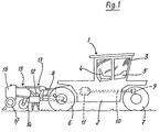
- Fig. 1 shows an agricultural tractor 1 with a chassis 2 and one extending upwards therefrom Driver's cabin 3. There is a seat 4 in driver's cabin 3 for the operator and a cockpit 5 with not shown Control elements for operating the drive or the Actuators arranged.
- a drive, not shown, is in a part of the chassis 2 between rear wheels 6 and front wheels 7 arranged. The drive motor is used for Driving the rear wheels 6 and the front wheels 7 on the one hand and to drive a rear PTO 8 and one front PTO, not shown.
- the rear PTO 8 is also over a transmission 12 connected to the drive motor.
- a rotary harrow 13 is connected at the PTO 8 .
- Behind the rotary harrow 13 a trailing roller 14 is arranged with which the Working depth of the rotary harrow 13 can be adjusted.
- the rotary harrow 13 is on the back with other lifting elements 15 equipped, to which, as can be seen from Fig. 1, a Sowing machine 16 articulated with supporting wheels 17 is.
- the tractor 1 has an autopilot function on, which enables the tractor 1 from one End of field to the other end of field without the influence of the Operator driving and steering controlled automatically becomes. For this purpose, the tractor 1 with a All-wheel steering equipped.
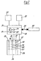
- the agricultural tractor 1 has, in the area of its cockpit 5, a device for controlling actuators, which is shown in FIG. 2.
- the device comprises a control unit 18 with a microprocessor 19, a read-write memory 20 (RAM), a read-only memory 20 '(ROM) and an interface 21. Via the interface 21, the control unit 18 is on the one hand with a Control unit 22 connected, which controls hydraulic cylinders as an electro-hydraulic hoist control for lifting or lowering lifting elements.
- the lifting member can be designed, for example, according to FIG. 1 as a rotary harrow 13 or as a plow.
- the control unit 18 is connected to a coupling unit 23 which has a plurality of working couplings for connection to further actuators.
- control unit 18 is electrically connected to an operating unit 24, which has a number of input keys 25, a number of automatic keys 26 and a number of reset keys 27.
- the control unit 18 outputs control signals to the control unit 22 or the clutch unit 23, so that corresponding control elements are actuated as actuators or actuators.
- the control unit is connected to a display unit 28 which has an LC display for displaying control-relevant data.
- the control unit 18 is electrically connected to a cockpit operating unit 30 via a bus system 29.
- the bus system 29 is preferably designed as a CAN bus or as an LBS bus.
- the cockpit control unit 30 comprises all control elements permanently attached in the cockpit 5.
- the control unit 18 is constructed in an integrated manner with the control unit 24 and the display unit 28 in a common structural unit. It has a plug-in device which enables the unit to be easily connected inside the cockpit 5.
- the control unit 18 is designed to be freely programmable, so that it can be connected to any work vehicle with a corresponding connection, in particular a bus connection.
- the device shown in Fig. 2 enables automation of the control processes shown in Fig. 3. For this it is necessary that the operator at a first Workflow according to the input flowchart Fig. 3, the corresponding control buttons for controlling the actuated respective actuators.
- the input process 31 'begins by pressing the enter key 31. This causes that control signals by actuating subsequent control buttons Delivered to the control unit 18 via the bus system 29 and in coded form in a memory area of the RAM memory 20 are stored.
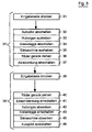
- the operator can provide that the operating element follows Switch off autopilot "32, the control element for Lift out lifting device “33, Switch off rotary harrow “34, Raise seed drill “35, Straighten wheels “36 and finally Switch on all-wheel steering "37 are actuated one after the other.
- These actuating functions are assigned to the automatic key 38 and can be activated automatically by actuating this key 38.
- the input key 39 is actuated within an input sequence 39 ′.
- the following controls are then operated in succession to return to the working position.
- First is the control element Straighten wheels "40 pressed, then the control element Switch on single-axle steering "41, Lower lifting element “42, Switch on rotary harrow “43, Lower the drill "44 and Switch on the autopilot "45.
- These control functions are assigned to an automatic key 46, so that after the automatic key 46 is pressed, these control functions are carried out automatically in succession.
- Each control flow is a reset button 47 which is closed the automatic button 38 corresponds, and a reset button 48, which corresponds to the automatic key 46 ⁇ assigned.
- a reset button 47 which is closed the automatic button 38 corresponds
- a reset button 48 which corresponds to the automatic key 46 ⁇ assigned.
- control process can be saved. Alternatively but also several rows of each corresponding input keys, automatic keys or reset buttons may be arranged. The control process however, it will exit as soon as the operator turns on the cockpit 5 fixed control element operated. The The operator can then continue control manually.
- the turning process of an agricultural tractor also in a temporal Sequence to be automated.
- the control unit 18 has a counter which is used for determination the time between two actuated controls serves.
- the counter can be used as an electrical unit Flip-flops can be formed.
- the counter also by one in a ROM 20 'of the control unit 18 stored program can be realized.
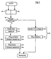
- the display unit 28 queries whether a time-dependent entry 50 is desired. If the operator confirms this query, after the start of the following input sequence 50 'with the actuation of the control element Packer solve "51 of the Counter switched on "52, so that it counts up, for example, until the further control element is actuated Raise the plow "53 the counter reading 54 resulting at this point in time is stored in the storage unit 20. When the control element is subsequently actuated Turn the plow "54, the next meter reading is determined, the difference to the previous meter reading is calculated and this value 56 is then stored in the RAM memory 20. This completes the input sequence 50 '.
- a plausibility program can also be stored in the RAM 20 be saved after actuation each control element within the input sequence 50 ', 59' checks that controls are in the correct order have been operated or whether the operation of a necessary Control element has been forgotten by the operator is.
- the plausibility program can check whether according to the flow chart of Fig. 3 at the beginning of Turning process the autopilot has been switched off or Not. If the operator has forgotten to switch off, can by a corresponding display in the display unit 28 or with a warning light made and / or the further operation of the control buttons automatically be blocked.
- the control unit 18 is also suitable for basic settings the control unit 22, e.g. Data about the amount of Hydraulic fluids or position of the throttle and available for the corresponding control process to deliver.
- the control can also be expanded that powertrain controls and regulations under Inclusion of the switching of engine characteristics or the Changes to vehicle strategies are saved and in Be taken into account as part of the control program.
- a vehicle steering unit can also be provided be connected to the control unit 18, so that the steering of multi-axle steered vehicles automatically can be controlled.
Landscapes
- Life Sciences & Earth Sciences (AREA)
- Engineering & Computer Science (AREA)
- Mechanical Engineering (AREA)
- Soil Sciences (AREA)
- Environmental Sciences (AREA)
- Lifting Devices For Agricultural Implements (AREA)
- Guiding Agricultural Machines (AREA)
Applications Claiming Priority (2)
| Application Number | Priority Date | Filing Date | Title |
|---|---|---|---|
| DE19630419 | 1996-07-27 | ||
| DE19630419A DE19630419A1 (de) | 1996-07-27 | 1996-07-27 | Vorrichtung zur Ansteuerung mindestes eines Stellorgans eines Arbeitsfahrzeuges |
Publications (4)
| Publication Number | Publication Date |
|---|---|
| EP0820688A2 true EP0820688A2 (fr) | 1998-01-28 |
| EP0820688A3 EP0820688A3 (fr) | 1998-03-18 |
| EP0820688B1 EP0820688B1 (fr) | 2001-12-12 |
| EP0820688B2 EP0820688B2 (fr) | 2007-07-25 |
Family
ID=7801071
Family Applications (1)
| Application Number | Title | Priority Date | Filing Date |
|---|---|---|---|
| EP97110720A Expired - Lifetime EP0820688B2 (fr) | 1996-07-27 | 1997-07-01 | Dispositif pour le contrôle au minimum d'un actionneur d'un véhicule utilitaire |
Country Status (4)
| Country | Link |
|---|---|
| US (1) | US6085134A (fr) |
| EP (1) | EP0820688B2 (fr) |
| DE (3) | DE19630419A1 (fr) |
| DK (1) | DK0820688T4 (fr) |
Cited By (4)
| Publication number | Priority date | Publication date | Assignee | Title |
|---|---|---|---|---|
| EP0934562A1 (fr) † | 1997-07-07 | 1999-08-11 | Case Corporation | Systeme repeteur de transmission d'ordres successifs pour vehicules tout terrain |
| DE10107139B4 (de) * | 2001-02-15 | 2004-09-23 | Gebr. Pöttinger GmbH | Pflug |
| EP2583544A1 (fr) | 2011-10-20 | 2013-04-24 | CLAAS Agrosystems KGaA mbH & Co KG. | Dispositif de visulaisation |
| EP2875708A1 (fr) * | 2013-11-08 | 2015-05-27 | Amazonen-Werke H. Dreyer GmbH & Co. KG | Système de commande pour une machine agricole |
Families Citing this family (9)
| Publication number | Priority date | Publication date | Assignee | Title |
|---|---|---|---|---|
| DE19904519A1 (de) * | 1999-02-04 | 2000-08-10 | Volkswagen Ag | Bedieneinheit, insbesondere multifunktionale Bedieneinheit |
| US6173225B1 (en) | 1999-04-20 | 2001-01-09 | Case Corporation | Power takeoff control system |
| DE102006049727A1 (de) * | 2006-10-21 | 2008-04-24 | Bayerische Motoren Werke Ag | Bedienkonzept zum Einstellen verschiedener Fahrdynamik-Charakteristika an einem Kraftfahrzeug |
| US7739015B2 (en) * | 2007-07-31 | 2010-06-15 | Deere & Company | System and method for controlling a vehicle with a sequence of vehicle events |
| US8209075B2 (en) | 2007-07-31 | 2012-06-26 | Deere & Company | Method and system for generating end turns |
| US8635011B2 (en) | 2007-07-31 | 2014-01-21 | Deere & Company | System and method for controlling a vehicle in response to a particular boundary |
| US8131432B2 (en) | 2008-02-27 | 2012-03-06 | Deere & Company | Method and system for managing the turning of a vehicle |
| US8204654B2 (en) * | 2008-03-20 | 2012-06-19 | Deere & Company | System and method for generation of an inner boundary of a work area |
| US9031749B2 (en) * | 2011-06-10 | 2015-05-12 | Great Plaines Manfacturing, Inc. | Cultivation air seeder having sequentially operated tools |
Citations (9)
| Publication number | Priority date | Publication date | Assignee | Title |
|---|---|---|---|---|
| US4932463A (en) * | 1988-10-14 | 1990-06-12 | Westinghouse Electric Corp. | Use of AC power in arc spray process |
| US4934463A (en) * | 1988-01-27 | 1990-06-19 | Caterpillar Inc. | Automatic implement position control system |
| US5050771A (en) † | 1989-07-31 | 1991-09-24 | Field Control Systems, Inc. | Repeatable pattern field spraying control |
| EP0448718A1 (fr) † | 1989-09-14 | 1991-10-02 | Fujitsu Limited | Methode et appareil pour traitement par un detecteur d'objets |
| DE4143140A1 (de) † | 1990-12-31 | 1992-07-02 | Samsung Heavy Ind | Vorrichtung und verfahren zur automatischen steuerung einer baumaschine |
| EP0494516A1 (fr) * | 1991-01-11 | 1992-07-15 | Massey Ferguson S.A. | Contrôle d'outil |
| US5188502A (en) * | 1990-12-24 | 1993-02-23 | Caterpillar, Inc. | Linkage arrangement for a multi-purpose vehicle |
| US5359517A (en) † | 1989-12-12 | 1994-10-25 | Kabushiki Kaisha Komatsu Seisakusho | Method and device for automating operation of construction machine |
| EP0697303A2 (fr) † | 1994-08-16 | 1996-02-21 | Deere & Company | Commande pour un véhicule de travail |
Family Cites Families (15)
| Publication number | Priority date | Publication date | Assignee | Title |
|---|---|---|---|---|
| FR2171967B1 (fr) * | 1972-02-17 | 1975-10-24 | Renault | |
| US4376298A (en) * | 1980-08-06 | 1983-03-08 | Dickey-John Corporation | Combine data center |
| DE3039975A1 (de) * | 1980-10-23 | 1982-05-27 | Wolfgang Dr. Dipl.-Phys. 7530 Pforzheim Herchenbach | Lenkvorrichtung fuer kraftfahrzeuge |
| FR2520185A1 (fr) * | 1982-01-22 | 1983-07-29 | Preciculture | Dispositif de guidage automatique du deplacement d'un vehicule, notamment d'un vehicule tous terrains |
| DE3318410C2 (de) * | 1983-05-20 | 1996-07-18 | Bosch Gmbh Robert | Verfahren zur Veränderung und Optimierung von Daten und Programmabläufen für programmierte Steuergeräte in Kraftfahrzeugen |
| NL8303818A (nl) * | 1983-11-07 | 1985-06-03 | Lely Nv C Van Der | Trekker. |
| AT380622B (de) * | 1984-07-06 | 1986-06-25 | Vogel & Noot Landmasch | Vorrichtung zum selbstaendigen regeln eines an einem landwirtschaftlichen schlepper angebauten arbeitsgeraetes, insbesondere drehpfluges |
| DE3427907A1 (de) * | 1984-07-28 | 1986-01-30 | Robert Bosch Gmbh, 7000 Stuttgart | Vorrichtung zum mechanischen messen und zum regeln der zugkraft einer zugmaschine |
| DE3438497C2 (de) * | 1984-10-19 | 1995-02-23 | Amazonen Werke Dreyer H | Landmaschine |
| EP0212304B2 (fr) * | 1985-08-16 | 1995-12-06 | Robert Bosch Gmbh | Dispositif électrohydraulique pour contrôler l'attelage de relevage d'un tracteur |
| DE8605352U1 (fr) * | 1986-02-27 | 1987-11-12 | Linde Ag, 6200 Wiesbaden, De | |
| US5217083A (en) * | 1989-08-08 | 1993-06-08 | Oshkosh Truck Corporation | All wheel steering system |
| IT1240172B (it) * | 1990-04-06 | 1993-11-27 | Weber Srl | Sistema di controllo di un veicolo |
| DE4138289A1 (de) * | 1991-11-21 | 1993-05-27 | Walterscheid Gmbh Jean | Zugstrebe |
| US5469356A (en) * | 1994-09-01 | 1995-11-21 | Caterpillar Inc. | System for controlling a vehicle to selectively allow operation in either an autonomous mode or a manual mode |
-
1996
- 1996-07-27 DE DE19630419A patent/DE19630419A1/de not_active Withdrawn
- 1996-07-27 DE DE29624492U patent/DE29624492U1/de not_active Expired - Lifetime
-
1997
- 1997-07-01 DK DK97110720T patent/DK0820688T4/da active
- 1997-07-01 EP EP97110720A patent/EP0820688B2/fr not_active Expired - Lifetime
- 1997-07-01 DE DE59705740T patent/DE59705740D1/de not_active Expired - Lifetime
- 1997-07-29 US US08/901,977 patent/US6085134A/en not_active Expired - Lifetime
Patent Citations (9)
| Publication number | Priority date | Publication date | Assignee | Title |
|---|---|---|---|---|
| US4934463A (en) * | 1988-01-27 | 1990-06-19 | Caterpillar Inc. | Automatic implement position control system |
| US4932463A (en) * | 1988-10-14 | 1990-06-12 | Westinghouse Electric Corp. | Use of AC power in arc spray process |
| US5050771A (en) † | 1989-07-31 | 1991-09-24 | Field Control Systems, Inc. | Repeatable pattern field spraying control |
| EP0448718A1 (fr) † | 1989-09-14 | 1991-10-02 | Fujitsu Limited | Methode et appareil pour traitement par un detecteur d'objets |
| US5359517A (en) † | 1989-12-12 | 1994-10-25 | Kabushiki Kaisha Komatsu Seisakusho | Method and device for automating operation of construction machine |
| US5188502A (en) * | 1990-12-24 | 1993-02-23 | Caterpillar, Inc. | Linkage arrangement for a multi-purpose vehicle |
| DE4143140A1 (de) † | 1990-12-31 | 1992-07-02 | Samsung Heavy Ind | Vorrichtung und verfahren zur automatischen steuerung einer baumaschine |
| EP0494516A1 (fr) * | 1991-01-11 | 1992-07-15 | Massey Ferguson S.A. | Contrôle d'outil |
| EP0697303A2 (fr) † | 1994-08-16 | 1996-02-21 | Deere & Company | Commande pour un véhicule de travail |
Non-Patent Citations (2)
| Title |
|---|
| Artikel von W. Friedrichsen und J. Möller, "Neue Entwicklingen und Tendenzen der Hydraulik in Landmaschinen und Ackerschleppern", in Ölhydraulik und Pneumatik, 1990, Nr.3, Seiten 148 bis 160 † |
| Bedienungsanleitung "Elektronische Pflugsteuerung, System EPS II" der Firma Weber-Hydraulik † |
Cited By (7)
| Publication number | Priority date | Publication date | Assignee | Title |
|---|---|---|---|---|
| EP0934562A1 (fr) † | 1997-07-07 | 1999-08-11 | Case Corporation | Systeme repeteur de transmission d'ordres successifs pour vehicules tout terrain |
| EP0934562B2 (fr) † | 1997-07-07 | 2015-08-05 | CNH Industrial Belgium nv | Systeme repeteur de transmission d'ordres successifs pour vehicules tout terrain |
| DE10107139B4 (de) * | 2001-02-15 | 2004-09-23 | Gebr. Pöttinger GmbH | Pflug |
| EP2583544A1 (fr) | 2011-10-20 | 2013-04-24 | CLAAS Agrosystems KGaA mbH & Co KG. | Dispositif de visulaisation |
| DE102011054630A1 (de) | 2011-10-20 | 2013-04-25 | Claas Agrosystems GmbH | Visualisierungseinrichtung |
| US9433140B2 (en) | 2011-10-20 | 2016-09-06 | Claas E-Systems Kgaa Mbh & Co Kg | Visualization device |
| EP2875708A1 (fr) * | 2013-11-08 | 2015-05-27 | Amazonen-Werke H. Dreyer GmbH & Co. KG | Système de commande pour une machine agricole |
Also Published As
| Publication number | Publication date |
|---|---|
| DK0820688T4 (da) | 2007-11-26 |
| EP0820688B2 (fr) | 2007-07-25 |
| EP0820688A3 (fr) | 1998-03-18 |
| DK0820688T3 (da) | 2002-04-15 |
| US6085134A (en) | 2000-07-04 |
| DE29624492U1 (de) | 2004-06-17 |
| DE19630419A1 (de) | 1998-01-29 |
| EP0820688B1 (fr) | 2001-12-12 |
| DE59705740D1 (de) | 2002-01-24 |
Similar Documents
| Publication | Publication Date | Title |
|---|---|---|
| EP0590692B1 (fr) | Système de commande pour le réglage de position de dispositifs d'attelage | |
| EP1915893B1 (fr) | Système de gestion de fonction pour véhicules | |
| EP0697303B1 (fr) | Commande pour un véhicule de travail | |
| DE10145643C1 (de) | Regelung für den Antrieb einer Zapfwelle an einem Landfahrzeug | |
| DE10014470C2 (de) | Displaysteuerungssystem für ein Arbeitsfahrzeug | |
| EP0820688B1 (fr) | Dispositif pour le contrôle au minimum d'un actionneur d'un véhicule utilitaire | |
| EP0377215B1 (fr) | Appareil et procédé pour étalonner un système de contrôle | |
| EP1048550A2 (fr) | Système de direction et machine de récolte | |
| EP2116120B1 (fr) | Méthode de commande d'une combinaison tracteur-outil agricole comprenant au moins un équipement échangeable | |
| EP1683674B1 (fr) | Dispositif de sélection de rapport de transmission d'une boîte de vitesses de prise de force | |
| EP1270306B1 (fr) | Commande de démarrage et d'arrêt d'une prise de force d'un véhicule agricole | |
| DE69818936T2 (de) | Verfahren und Einrichtung zur Automatisierung von sich wiederholenden Aufgaben | |
| DE19649273C2 (de) | Landwirtschaftliches Nutzfahrzeug mit einem lagegeregelten Hubwerk und ein Verfahren zur Lageregelung eines Hubwerks in landwirtschaftlichen Nutzfahrzeugen | |
| EP3400769A1 (fr) | Machine de travail agricole et procédé de fonctionnement d'une machine de travail agricole | |
| EP1300061B1 (fr) | Procédé et dispositif pour la détermination des paramètres pour les travaux de champs | |
| EP3653033B1 (fr) | Procédé de fonctionnement d'une prise de force d'un tracteur agricole doté d'un mécanisme de levage d'éléments rapportés | |
| DE10304377B3 (de) | Anordnung und Verfahren zur Steuerung eines Hubwerkes eines landwirtschaftlichen Nutzfahrzeuges | |
| DE102015224747A1 (de) | Feldrandbereich-betriebssteuerungssystem | |
| EP3072375B2 (fr) | Interface homme-machine pour un engin agricole, systeme de commande, engin agricole et procede de fonctionnement associe | |
| DE19754233A1 (de) | Steuereinrichtung für Zapfwellen | |
| EP1897743B1 (fr) | Véhicule agricole et procédé de fonctionnement d'un frein d'une prise de force d'un véhicule agricole | |
| DE102019208346A1 (de) | Landwirtschaftlicher Traktor mit einem an diesen ankuppelbaren Anbaugerät sowie Verfahren zum Betrieb eines landwirtschaftlichen Traktors mit einem an diesen ankuppelbaren Anbaugerät | |
| EP4124220A1 (fr) | Procédé d'aide à un processus d'accouplement à mettre en uvre dans un relevage à trois points | |
| DD276016A1 (de) | Steuervorrichtung fuer anhaengemaschinen |
Legal Events
| Date | Code | Title | Description |
|---|---|---|---|
| PUAI | Public reference made under article 153(3) epc to a published international application that has entered the european phase |
Free format text: ORIGINAL CODE: 0009012 |
|
| AK | Designated contracting states |
Kind code of ref document: A2 Designated state(s): DE DK FR GB IT SE |
|
| PUAL | Search report despatched |
Free format text: ORIGINAL CODE: 0009013 |
|
| AK | Designated contracting states |
Kind code of ref document: A3 Designated state(s): AT BE CH DE DK ES FI FR GB GR IE IT LI LU MC NL PT SE |
|
| 17P | Request for examination filed |
Effective date: 19980918 |
|
| AKX | Designation fees paid |
Free format text: DE DK FR GB IT SE |
|
| RBV | Designated contracting states (corrected) |
Designated state(s): DE DK FR GB IT SE |
|
| 17Q | First examination report despatched |
Effective date: 20001206 |
|
| GRAG | Despatch of communication of intention to grant |
Free format text: ORIGINAL CODE: EPIDOS AGRA |
|
| GRAG | Despatch of communication of intention to grant |
Free format text: ORIGINAL CODE: EPIDOS AGRA |
|
| GRAH | Despatch of communication of intention to grant a patent |
Free format text: ORIGINAL CODE: EPIDOS IGRA |
|
| ITF | It: translation for a ep patent filed |
Owner name: DE DOMINICIS & MAYER S.R.L. |
|
| GRAH | Despatch of communication of intention to grant a patent |
Free format text: ORIGINAL CODE: EPIDOS IGRA |
|
| GRAA | (expected) grant |
Free format text: ORIGINAL CODE: 0009210 |
|
| AK | Designated contracting states |
Kind code of ref document: B1 Designated state(s): DE DK FR GB IT SE |
|
| REG | Reference to a national code |
Ref country code: GB Ref legal event code: IF02 |
|
| REF | Corresponds to: |
Ref document number: 59705740 Country of ref document: DE Date of ref document: 20020124 |
|
| GBT | Gb: translation of ep patent filed (gb section 77(6)(a)/1977) |
Effective date: 20020226 |
|
| REG | Reference to a national code |
Ref country code: DK Ref legal event code: T3 |
|
| PLBQ | Unpublished change to opponent data |
Free format text: ORIGINAL CODE: EPIDOS OPPO |
|
| PLBI | Opposition filed |
Free format text: ORIGINAL CODE: 0009260 |
|
| PLBF | Reply of patent proprietor to notice(s) of opposition |
Free format text: ORIGINAL CODE: EPIDOS OBSO |
|
| 26 | Opposition filed |
Opponent name: DEERE & COMPANY Effective date: 20020809 |
|
| PLBF | Reply of patent proprietor to notice(s) of opposition |
Free format text: ORIGINAL CODE: EPIDOS OBSO |
|
| PLBF | Reply of patent proprietor to notice(s) of opposition |
Free format text: ORIGINAL CODE: EPIDOS OBSO |
|
| APBP | Date of receipt of notice of appeal recorded |
Free format text: ORIGINAL CODE: EPIDOSNNOA2O |
|
| APBQ | Date of receipt of statement of grounds of appeal recorded |
Free format text: ORIGINAL CODE: EPIDOSNNOA3O |
|
| APAA | Appeal reference recorded |
Free format text: ORIGINAL CODE: EPIDOS REFN |
|
| APAH | Appeal reference modified |
Free format text: ORIGINAL CODE: EPIDOSCREFNO |
|
| APBU | Appeal procedure closed |
Free format text: ORIGINAL CODE: EPIDOSNNOA9O |
|
| PUAH | Patent maintained in amended form |
Free format text: ORIGINAL CODE: 0009272 |
|
| STAA | Information on the status of an ep patent application or granted ep patent |
Free format text: STATUS: PATENT MAINTAINED AS AMENDED |
|
| 27A | Patent maintained in amended form |
Effective date: 20070725 |
|
| AK | Designated contracting states |
Kind code of ref document: B2 Designated state(s): DE DK FR GB IT SE |
|
| GBTA | Gb: translation of amended ep patent filed (gb section 77(6)(b)/1977) | ||
| REG | Reference to a national code |
Ref country code: SE Ref legal event code: RPEO |
|
| ET3 | Fr: translation filed ** decision concerning opposition | ||
| REG | Reference to a national code |
Ref country code: DK Ref legal event code: T4 |
|
| REG | Reference to a national code |
Ref country code: FR Ref legal event code: PLFP Year of fee payment: 19 |
|
| PGFP | Annual fee paid to national office [announced via postgrant information from national office to epo] |
Ref country code: DE Payment date: 20150528 Year of fee payment: 19 Ref country code: GB Payment date: 20150724 Year of fee payment: 19 Ref country code: DK Payment date: 20150727 Year of fee payment: 19 |
|
| PGFP | Annual fee paid to national office [announced via postgrant information from national office to epo] |
Ref country code: SE Payment date: 20150724 Year of fee payment: 19 Ref country code: FR Payment date: 20150730 Year of fee payment: 19 |
|
| PGFP | Annual fee paid to national office [announced via postgrant information from national office to epo] |
Ref country code: IT Payment date: 20150728 Year of fee payment: 19 |
|
| REG | Reference to a national code |
Ref country code: DE Ref legal event code: R119 Ref document number: 59705740 Country of ref document: DE |
|
| REG | Reference to a national code |
Ref country code: DK Ref legal event code: EBP Effective date: 20170131 |
|
| REG | Reference to a national code |
Ref country code: SE Ref legal event code: EUG |
|
| GBPC | Gb: european patent ceased through non-payment of renewal fee |
Effective date: 20160701 |
|
| PG25 | Lapsed in a contracting state [announced via postgrant information from national office to epo] |
Ref country code: SE Free format text: LAPSE BECAUSE OF NON-PAYMENT OF DUE FEES Effective date: 20160702 Ref country code: FR Free format text: LAPSE BECAUSE OF NON-PAYMENT OF DUE FEES Effective date: 20160801 Ref country code: DE Free format text: LAPSE BECAUSE OF NON-PAYMENT OF DUE FEES Effective date: 20170201 |
|
| REG | Reference to a national code |
Ref country code: FR Ref legal event code: ST Effective date: 20170331 |
|
| PG25 | Lapsed in a contracting state [announced via postgrant information from national office to epo] |
Ref country code: GB Free format text: LAPSE BECAUSE OF NON-PAYMENT OF DUE FEES Effective date: 20160701 |
|
| PG25 | Lapsed in a contracting state [announced via postgrant information from national office to epo] |
Ref country code: IT Free format text: LAPSE BECAUSE OF NON-PAYMENT OF DUE FEES Effective date: 20160701 |
|
| PG25 | Lapsed in a contracting state [announced via postgrant information from national office to epo] |
Ref country code: DK Free format text: LAPSE BECAUSE OF NON-PAYMENT OF DUE FEES Effective date: 20160731 |