EP0820688A2 - Device for controlling at least one actuator of a utility vehicle - Google Patents
Device for controlling at least one actuator of a utility vehicle Download PDFInfo
- Publication number
- EP0820688A2 EP0820688A2 EP97110720A EP97110720A EP0820688A2 EP 0820688 A2 EP0820688 A2 EP 0820688A2 EP 97110720 A EP97110720 A EP 97110720A EP 97110720 A EP97110720 A EP 97110720A EP 0820688 A2 EP0820688 A2 EP 0820688A2
- Authority
- EP
- European Patent Office
- Prior art keywords
- control unit
- control
- functions
- unit
- data
- Prior art date
- Legal status (The legal status is an assumption and is not a legal conclusion. Google has not performed a legal analysis and makes no representation as to the accuracy of the status listed.)
- Granted
Links
Images
Classifications
-
- A—HUMAN NECESSITIES
- A01—AGRICULTURE; FORESTRY; ANIMAL HUSBANDRY; HUNTING; TRAPPING; FISHING
- A01B—SOIL WORKING IN AGRICULTURE OR FORESTRY; PARTS, DETAILS, OR ACCESSORIES OF AGRICULTURAL MACHINES OR IMPLEMENTS, IN GENERAL
- A01B63/00—Lifting or adjusting devices or arrangements for agricultural machines or implements
- A01B63/02—Lifting or adjusting devices or arrangements for agricultural machines or implements for implements mounted on tractors
- A01B63/10—Lifting or adjusting devices or arrangements for agricultural machines or implements for implements mounted on tractors operated by hydraulic or pneumatic means
Definitions
- the invention relates to a device for control at least one actuator of a work vehicle, in particular an agricultural tractor, according to the preamble of the claim 1.
- DE 34 40 625 C2 describes a control device at least one actuator of a work vehicle known with an electronic control unit that the Automatic vehicle lifting maneuvers controls or lowering the actuators.
- the control unit has a series of timers that are sequential Adjusting the actuators in a fixed predetermined Cause time sequence.
- a disadvantage of this device is that the application of the device to the Turning is limited and that the operator during driving in the work vehicle has no influence on the Sequence of actuating functions can take.
- DE 44 28 824 A1 describes a control device known at least one actuator, which is a control unit includes a number of control functions that run according to a fixed program. By pressing an automatic switch, the control unit opens Ready switched. With actuation of another operating switch the program is started, so that afterwards a sequence of control functions by the actuators be processed. For example, after Operating the control switch the hoist from the working position brought into the transport position and at the same time the differential lock is switched off. The adjustment follows further actuators until the work vehicle in the Excavated state has passed. This device too has the disadvantage that the operator has no influence can take on the sequence of control functions.
- the invention enables an operator to be able to is shifted by operating any control element Setting functions automatically in a desired order to be carried out.
- the operator only needs in a first workflow as the input process Manually operate the sequence of controls selected by him then after activation by actuating an automatic element expires automatically. That way one adapted to the individual needs of the operator Automation of control processes implemented. This can advantageously meet the requirements of field processing depending on the climatic conditions by additional loading or control of a Actuator are taken into account.
- control unit an operating unit assigned to at least one Input switch to start the input process, at least an automatic switch for calling up or starting the automatic process and at least one reset switch to clear of the automatic process. So that several automatic processes are stored and can be called up, the control unit shows several input, corresponding to each other, Automatic and reset switch on.
- control unit is a Assigned display unit that the to be stored or stored control functions visualized and thus the Operator control over the running control functions gives.
- control unit is integrated with the operating unit and the display unit in a common structural unit.
- structural unit is designed to be detachable from the cockpit of the work vehicle, so that after the plug-and-play technology "can be used with appropriate programming in several work vehicles.
- the control unit is advantageously connected via a bus system to the operating elements permanently installed in the work vehicle, so that these can be actuated in the input sequence in a way that the operator is used to.
- the operator also about the timing of the control functions determine.
- the invention finds application in agriculture used work vehicles such. B. in agricultural tractors with connected lifting devices or with self-propelled Harvesters, such as beet or potato harvesters and forage harvesters.
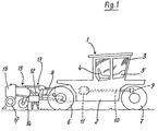
- Fig. 1 shows an agricultural tractor 1 with a chassis 2 and one extending upwards therefrom Driver's cabin 3. There is a seat 4 in driver's cabin 3 for the operator and a cockpit 5 with not shown Control elements for operating the drive or the Actuators arranged.
- a drive, not shown, is in a part of the chassis 2 between rear wheels 6 and front wheels 7 arranged. The drive motor is used for Driving the rear wheels 6 and the front wheels 7 on the one hand and to drive a rear PTO 8 and one front PTO, not shown.
- the rear PTO 8 is also over a transmission 12 connected to the drive motor.
- a rotary harrow 13 is connected at the PTO 8 .
- Behind the rotary harrow 13 a trailing roller 14 is arranged with which the Working depth of the rotary harrow 13 can be adjusted.
- the rotary harrow 13 is on the back with other lifting elements 15 equipped, to which, as can be seen from Fig. 1, a Sowing machine 16 articulated with supporting wheels 17 is.
- the tractor 1 has an autopilot function on, which enables the tractor 1 from one End of field to the other end of field without the influence of the Operator driving and steering controlled automatically becomes. For this purpose, the tractor 1 with a All-wheel steering equipped.
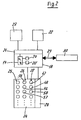
- the agricultural tractor 1 has, in the area of its cockpit 5, a device for controlling actuators, which is shown in FIG. 2.
- the device comprises a control unit 18 with a microprocessor 19, a read-write memory 20 (RAM), a read-only memory 20 '(ROM) and an interface 21. Via the interface 21, the control unit 18 is on the one hand with a Control unit 22 connected, which controls hydraulic cylinders as an electro-hydraulic hoist control for lifting or lowering lifting elements.
- the lifting member can be designed, for example, according to FIG. 1 as a rotary harrow 13 or as a plow.
- the control unit 18 is connected to a coupling unit 23 which has a plurality of working couplings for connection to further actuators.
- control unit 18 is electrically connected to an operating unit 24, which has a number of input keys 25, a number of automatic keys 26 and a number of reset keys 27.
- the control unit 18 outputs control signals to the control unit 22 or the clutch unit 23, so that corresponding control elements are actuated as actuators or actuators.
- the control unit is connected to a display unit 28 which has an LC display for displaying control-relevant data.
- the control unit 18 is electrically connected to a cockpit operating unit 30 via a bus system 29.
- the bus system 29 is preferably designed as a CAN bus or as an LBS bus.
- the cockpit control unit 30 comprises all control elements permanently attached in the cockpit 5.
- the control unit 18 is constructed in an integrated manner with the control unit 24 and the display unit 28 in a common structural unit. It has a plug-in device which enables the unit to be easily connected inside the cockpit 5.
- the control unit 18 is designed to be freely programmable, so that it can be connected to any work vehicle with a corresponding connection, in particular a bus connection.
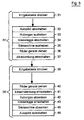
- the device shown in Fig. 2 enables automation of the control processes shown in Fig. 3. For this it is necessary that the operator at a first Workflow according to the input flowchart Fig. 3, the corresponding control buttons for controlling the actuated respective actuators.
- the input process 31 'begins by pressing the enter key 31. This causes that control signals by actuating subsequent control buttons Delivered to the control unit 18 via the bus system 29 and in coded form in a memory area of the RAM memory 20 are stored.
- the operator can provide that the operating element follows Switch off autopilot "32, the control element for Lift out lifting device “33, Switch off rotary harrow “34, Raise seed drill “35, Straighten wheels “36 and finally Switch on all-wheel steering "37 are actuated one after the other.
- These actuating functions are assigned to the automatic key 38 and can be activated automatically by actuating this key 38.
- the input key 39 is actuated within an input sequence 39 ′.
- the following controls are then operated in succession to return to the working position.
- First is the control element Straighten wheels "40 pressed, then the control element Switch on single-axle steering "41, Lower lifting element “42, Switch on rotary harrow “43, Lower the drill "44 and Switch on the autopilot "45.
- These control functions are assigned to an automatic key 46, so that after the automatic key 46 is pressed, these control functions are carried out automatically in succession.
- Each control flow is a reset button 47 which is closed the automatic button 38 corresponds, and a reset button 48, which corresponds to the automatic key 46 ⁇ assigned.
- a reset button 47 which is closed the automatic button 38 corresponds
- a reset button 48 which corresponds to the automatic key 46 ⁇ assigned.
- control process can be saved. Alternatively but also several rows of each corresponding input keys, automatic keys or reset buttons may be arranged. The control process however, it will exit as soon as the operator turns on the cockpit 5 fixed control element operated. The The operator can then continue control manually.
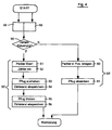
- the turning process of an agricultural tractor also in a temporal Sequence to be automated.
- the control unit 18 has a counter which is used for determination the time between two actuated controls serves.
- the counter can be used as an electrical unit Flip-flops can be formed.
- the counter also by one in a ROM 20 'of the control unit 18 stored program can be realized.
- the display unit 28 queries whether a time-dependent entry 50 is desired. If the operator confirms this query, after the start of the following input sequence 50 'with the actuation of the control element Packer solve "51 of the Counter switched on "52, so that it counts up, for example, until the further control element is actuated Raise the plow "53 the counter reading 54 resulting at this point in time is stored in the storage unit 20. When the control element is subsequently actuated Turn the plow "54, the next meter reading is determined, the difference to the previous meter reading is calculated and this value 56 is then stored in the RAM memory 20. This completes the input sequence 50 '.
- a plausibility program can also be stored in the RAM 20 be saved after actuation each control element within the input sequence 50 ', 59' checks that controls are in the correct order have been operated or whether the operation of a necessary Control element has been forgotten by the operator is.
- the plausibility program can check whether according to the flow chart of Fig. 3 at the beginning of Turning process the autopilot has been switched off or Not. If the operator has forgotten to switch off, can by a corresponding display in the display unit 28 or with a warning light made and / or the further operation of the control buttons automatically be blocked.
- the control unit 18 is also suitable for basic settings the control unit 22, e.g. Data about the amount of Hydraulic fluids or position of the throttle and available for the corresponding control process to deliver.
- the control can also be expanded that powertrain controls and regulations under Inclusion of the switching of engine characteristics or the Changes to vehicle strategies are saved and in Be taken into account as part of the control program.
- a vehicle steering unit can also be provided be connected to the control unit 18, so that the steering of multi-axle steered vehicles automatically can be controlled.
Abstract
Description
Die Erfindung betrifft eine Vorrichtung zur Ansteuerung
mindestens eines Stellorgans eines Arbeitsfahrzeugs, insbesondere
eines Ackerschleppers, nach dem Oberbegriff des Patentanspruchs
1.The invention relates to a device for control
at least one actuator of a work vehicle, in particular
an agricultural tractor, according to the preamble of the
Aus der DE 34 40 625 C2 ist eine Vorrichtung zur Ansteuerung mindestens eines Stellorgans eines Arbeitsfahrzeugs mit einer elektronischen Steuereinheit bekannt, die das Wendemanöver des Arbeitsfahrzeugs durch automatisches Anheben bzw. Absenken der Stellorgane steuert. Die Steuereinheit weist eine Reihe von Zeitgebern auf, die das aufeinanderfolgende Verstellen der Stellorgane in einer fest vorgegebenen Zeitfolge verursachen. Nachteilig an dieser Vorrichtung ist, daß die Anwendung der Vorrichtung auf den Wendevorgang beschränkt ist und daß die Bedienperson während der Fahrt im Arbeitsfahrzeug keinen Einfluß auf die Abfolge der Stellfunktionen nehmen kann.DE 34 40 625 C2 describes a control device at least one actuator of a work vehicle known with an electronic control unit that the Automatic vehicle lifting maneuvers controls or lowering the actuators. The control unit has a series of timers that are sequential Adjusting the actuators in a fixed predetermined Cause time sequence. A disadvantage of this device is that the application of the device to the Turning is limited and that the operator during driving in the work vehicle has no influence on the Sequence of actuating functions can take.
Aus der DE 44 28 824 A1 ist eine Vorrichtung zur Ansteuerung mindestens eines Stell-organs bekannt, die eine Steuereinheit umfaßt mit einer Reihe von Stellfunktionen, die nach einem fest vorgegebenen Programm ablaufen. Durch Betätigen eines Automatikschalters wird die Steuereinheit auf Bereitschaft geschaltet. Mit Betätigen eines weiteren Bedienschalters wird das Programm gestartet, so daß anschließend eine Folge von Steuerfunktionen durch die Stellorgane abgearbeitet werden. Beispielsweise wird nach dem Betätigen des Bedienschalters das Hubwerk aus der Arbeitsposition in die Transportposition gebracht und gleichzeitig die Differentialsperre ausgeschaltet. Es folgt die Verstellung weiterer Stellorgane, bis das Arbeitsfahrzeug in den Aushubzustand übergegangen ist. Auch diese Vorrichtung weist den Nachteil auf, daß die Bedienperson keinen Einfluß nehmen kann auf die Abfolge der Steuerfunktionen.DE 44 28 824 A1 describes a control device known at least one actuator, which is a control unit includes a number of control functions that run according to a fixed program. By pressing an automatic switch, the control unit opens Ready switched. With actuation of another operating switch the program is started, so that afterwards a sequence of control functions by the actuators be processed. For example, after Operating the control switch the hoist from the working position brought into the transport position and at the same time the differential lock is switched off. The adjustment follows further actuators until the work vehicle in the Excavated state has passed. This device too has the disadvantage that the operator has no influence can take on the sequence of control functions.
Es ist daher Aufgabe der Erfindung, eine Vorrichtung zur Ansteuerung mindestens eines Stellorgans eines Arbeitsfahrzeugs derart weiter auszubilden, daß die vorgenannten Nachteile vermieden und der Bedienkomfort für die Bedienperson erhöht wird, ohne daß Fehlfunktionen auftreten können.It is therefore an object of the invention to provide a device for Control of at least one control element of a work vehicle to train such that the aforementioned disadvantages avoided and the ease of use for the operator is increased without malfunctions occurring.
Die Erfindung ermöglicht, daß eine Bedienperson in die Lage versetzt wird, durch Bedienung eines Bedienelements beliebige Stellfunktionen in einer gewünschten Reihenfolge automatisch ausführen zu lassen. Die Bedienperson braucht lediglich in einem ersten Arbeitsablauf als Eingabeablauf die von ihm gewählte Bedienelementfolge manuell betätigen, die darauf folgend nach Aktivierung durch Betätigung eines Automatikelements automatisch abläuft. Auf diese Weise wird eine an den individuellen Bedürfnissen der Bedienperson angepaßte Automatisierung der Steuerungsabläufe verwirklicht. Vorteilhafterweise kann so den Erfordernissen der Feldbearbeitung in Abhängigkeit von den klimatischen Bedingungen durch zusätzliche Beaufschlagung bzw. Ansteuerung eines Stellorgans Rechnung getragen werden.The invention enables an operator to be able to is shifted by operating any control element Setting functions automatically in a desired order to be carried out. The operator only needs in a first workflow as the input process Manually operate the sequence of controls selected by him then after activation by actuating an automatic element expires automatically. That way one adapted to the individual needs of the operator Automation of control processes implemented. This can advantageously meet the requirements of field processing depending on the climatic conditions by additional loading or control of a Actuator are taken into account.
Nach einer Ausgestaltung der Erfindung ist der Steuereinheit eine Bedieneinheit zugeordnet, die mindestens einen Eingabeschalter zum Starten des Eingabeablaufs, mindestens einen Automatikschalter zum Abrufen bzw. Starten des Automatikablaufs und mindestens einen Rücksetzschalter zum Löschen des Automatikablaufs aufweist. Damit mehrere Automatikabläufe gespeichert und abrufbar sind, weist die Bedieneinheit mehrere, jeweils zueinander korrespondierende Eingabe-, Automatik- und Rücksetzschalter auf.According to one embodiment of the invention, the control unit an operating unit assigned to at least one Input switch to start the input process, at least an automatic switch for calling up or starting the automatic process and at least one reset switch to clear of the automatic process. So that several automatic processes are stored and can be called up, the control unit shows several input, corresponding to each other, Automatic and reset switch on.
In Weiterbildung der Erfindung ist der Steuereinheit eine Anzeigeeinheit zugeordnet, die die abzuspeichernden bzw. abgespeicherten Stellfunktionen visualisiert und damit der Bedienperson eine Kontrolle über die ablaufenden Stellfunktionen gibt.In a development of the invention, the control unit is a Assigned display unit that the to be stored or stored control functions visualized and thus the Operator control over the running control functions gives.
Nach einer Ausgestaltung der Erfindung ist die Steuereinheit
mit der Bedieneinheit und der Anzeigeeinheit in einer
gemeinsamen Baueinheit integriert. Vorteilhafterweise ist
die Baueinheit abnehmbar von dem Cockpit des Arbeitsfahrzeugs
ausgebildet, so daß sie nach der ![]()
![]()
Nach einer Ausgestaltung der Erfindung kann die Bedienperson auch über die zeitliche Abfolge der Steuerfunktionen bestimmen. Dadurch, daß die Zeitintervalle zwischen den einzelnen betätigten Bedienelementen im Eingabeablauf erfaßt und gespeichert werden, kann beispielsweise der Wendevorgang weitgehend automatisiert werden.According to one embodiment of the invention, the operator also about the timing of the control functions determine. The fact that the time intervals between the individually operated controls in the input process and can be saved, for example, the turning process be largely automated.
Weitere Vorteile der Erfindung sind in den weiteren Unteransprüchen angegeben.Further advantages of the invention are in the further subclaims specified.
Ausführungsbeispiele der Erfindung werden nachfolgend anhand der Zeichnungen näher erläutert.Exemplary embodiments of the invention are described below the drawings explained in more detail.
Es zeigen:
- Fig. 1
- eine Seitenansicht eines Arbeitsfahrzeugs mit am Heck angebrachten Hebeorganen,
- Fig. 2
- ein Blockschaltbild der erfindungsgemäßen Vorrichtung,
- Fig. 3
- ein Flußdiagramm eines selbsttätig lenkenden Arbeitsfahrzeugs beim Wendevorgang und
- Fig. 4
- ein Flußdiagramm eines Eingabeablaufs für ein Wendemanöver eines Arbeitsfahrzeugs mit einem angeschlossenen Pflug.
- Fig. 1
- a side view of a work vehicle with lifting elements attached to the rear,
- Fig. 2
- 2 shows a block diagram of the device according to the invention,
- Fig. 3
- a flowchart of an automatically steering work vehicle during the turning process and
- Fig. 4
- a flowchart of an input sequence for a turning maneuver of a work vehicle with a connected plow.
Die Erfindung findet Anwendung bei in der Landwirtschaft eingesetzten Arbeitsfahrzeugen, wie z. B. bei Ackerschleppern mit angeschlossenen Huborganen oder bei selbstfahrenden Erntemaschinen, wie beispielsweise bei Rüben- oder Kartoffelerntemaschinen sowie Feldhäckslern.The invention finds application in agriculture used work vehicles such. B. in agricultural tractors with connected lifting devices or with self-propelled Harvesters, such as beet or potato harvesters and forage harvesters.
Die Fig. 1 zeigt einen Ackerschlepper 1 mit einem Fahrgestell
2 und einer sich von diesem nach oben hin erstreckenden
Fahrerkabine 3. In der Fahrerkabine 3 ist ein Sitz 4
für die Bedienperson sowie ein Cockpit 5 mit nicht gezeigten
Bedienelementen zum Betätigen des Antriebs bzw. der
Stellorgane angeordnet. Ein nicht dargestellter Antrieb ist
in einem Teil des Fahrgestells 2 zwischen Hinterrädern 6
und Vorderrädern 7 angeordnet. Der Antriebsmotor dient zum
Antreiben der Hinterräder 6 und der Vorderräder 7 einerseits
und zum Antrieb einer hinteren Zapfwelle 8 und einer
nicht dargestellten vorderen Zapfwelle.Fig. 1 shows an
Zum Anschluß der vorderen Zapfwelle ist ein Zapfwellenanschluß
9 mit einem eine Welle aufweisenden Führungsrohr 10
vorgesehen, das von dem Antriebsmotor über ein Getriebe 11
antreibbar ist. Die hintere Zapfwelle 8 ist ebenfalls über
ein Getriebe 12 mit dem Antriebsmotor verbunden. An der
Zapfwelle 8 ist eine Kreuzgelenkwelle angelenkt, über die
eine Kreiselegge 13 angeschlossen ist. Hinter der Kreiselegge
13 ist eine Nachlaufwalze 14 angeordnet, mit der die
Arbeitstiefe der Kreiselegge 13 eingestellt werden kann.
Die Kreiselegge 13 ist rückseitig mit weiteren Huborganen
15 ausgestattet, an die, wie aus Fig. 1 zu ersehen ist, eine
Sähmaschine 16 mit abstützenden Laufrädern 17 angelenkt
ist. Der Ackerschlepper 1 weist eine Autopilot-Funktion
auf, die es ermöglicht, daß der Ackerschlepper 1 von einem
Feldende zum anderen Feldende ohne Einflußnahme durch die
Bedienperson selbsttätig fahrend und lenkend gesteuert
wird. Zu diesem Zweck ist der Ackerschlepper 1 mit einer
Allradlenkung ausgestattet.There is a PTO connection for connecting the
Zur Erhöhung des Bedienungskomforts weist der Ackerschlepper
1 im Bereich seines Cockpits 5 eine in Fig. 2 dargestellte
Vorrichtung zur Ansteuerung von Stellorganen auf.
Die Vorrichtung umfaßt eine Steuereinheit 18 mit einem Mikroprozessor
19, einem Schreib-Lese-Speicher 20 (RAM), einem
Nur-Lese-Speicher 20' (ROM) sowie einer Schnittstelle
21. Über die Schnittstelle 21 ist die Steuereinheit 18 zum
einen mit einer Regeleinheit 22 verbunden, die als elektrohydraulische
Hubwerksregelung Hydraulikzylinder ansteuert
zum Heben bzw. Absenken von Huborganen. Das Huborgan
kann beispielsweise gemäß Fig. 1 als Kreiselegge 13 oder
als Pflug ausgebildet sein. Zum zweiten ist die Steuereinheit
18 mit einer Kupplungseinheit 23 verbunden, die eine
Mehrzahl von Arbeitskupplungen aufweist zur Verbindung mit
weiteren Stellorganen. Weiterhin ist die Steuereinheit 18
elektrisch mit einer Bedieneinheit 24 verbunden, die eine
Reihe von Eingabetasten 25, eine Reihe von Automatiktasten
26 und eine Reihe von Rücksetztasten 27 aufweist. Die Steuereinheit
18 gibt Stellsignale an die Regeleinheit 22 oder
die Kupplungseinheit 23 ab, so daß entsprechende Stellorgane
als Stellglieder oder Aktoren angesteuert werden. Darüber
hinaus ist die Steuereinheit mit einer Anzeigeeinheit
28 verbunden, die ein LC-Display aufweist zur Anzeige von
steuerungsrelevanten Daten. Ferner ist die Steuereinheit 18
über ein Bussystem 29 mit einer Cockpit-Bedieneinheit 30
elektrisch verbunden. Das Bussystem 29 ist vorzugsweise als
CAN-Bus oder als LBS-Bus ausgebildet. Die Cockpit-Bedieneinheit
30 umfaßt alle fest im Cockpit 5 angebrachten
Bedienelemente.
Die Steuereinheit 18 ist mit der Bedieneinheit 24 und der
Anzeigeeinheit 28 in einer gemeinsamen Baueinheit integriert
aufgebaut. Sie weist eine Steckeinrichtung auf, dieein
einfaches Anschließen der Baueinheit innerhalb des
Cockpits 5 ermöglicht. Darüber hinaus ist die Steuereinheit
18 frei programmierbar ausgestaltet, so daß sie an jedes
Arbeitfahrzeug mit einem entsprechenden Anschluß, insbesondere
einen Bus-Anschluß, angeschlossen werden kann.To increase the ease of use, the
The
Die in Fig. 2 dargestellte Vorrichtung ermöglicht die Automatisierung
der in Fig. 3 dargestellten Steuerungsabläufe.
Dazu ist es notwendig, daß die Bedienperson bei einem ersten
Arbeitsablauf entsprechend des Eingabeablaufplans nach
Fig. 3 die entsprechenden Bedientasten zur Ansteuerung der
jeweiligen Stellorgane betätigt. Der Eingabeablauf 31' beginnt
mit dem Betätigen der Eingabetaste 31. Diese bewirkt,
daß durch die Betätigung nachfolgender Bedientasten Steuersignale
über das Bussystem 29 an die Steuereinheit 18 abgegeben
werden und in codierter Form in einem Speicherbereich
des RAM-Speichers 20 abgelegt werden. The device shown in Fig. 2 enables automation
of the control processes shown in Fig. 3.
For this it is necessary that the operator at a first
Workflow according to the input flowchart
Fig. 3, the corresponding control buttons for controlling the
actuated respective actuators. The input process 31 'begins
by pressing the
Zur Einleitung eines Wendevorgangs des in Fig. 1 beschriebenen
Ackerschleppers 1 kann die Bedienperson gemäß Fig. 3
vorsehen, daß nachfolgend das Bedienelement
Nach Beendigung des Wendevorgangs wird innerhalb eines Eingabeablaufs
39' die Eingabetaste 39 betätigt. Nachfolgend
werden folgende Bedienelemente aufeinanderfolgend betätigt,
um in die Arbeitsstellung zurückzukehren. Als erstes wird
das Bedienelement
Jedem Steuerungsablauf ist eine Rücksetztaste 47, die zu
der Automatiktaste 38 korrespondiert, sowie eine Rücksetztaste
48, die zu der Automatiktaste 46 korrespondiert`
zugeordnet. Bei Betätigung der Rücksetztasten 47, 48 wird
der die jeweiligen Eingabeabläufe 31', 39' zugeordnete
Speicherbereich des Speichers 20 zurückgesetzt, so daß über
die Eingabetasten 31, 39 neue, veränderte Eingabeabläufe
abgespeichert werden können.Each control flow is a
Gemäß Fig. 2 sind vier Steuerungsabläufe abspeicherbar. Alternativ
dazu können aber auch mehrere Reihen von jeweils
zueinander korrespondierenden Eingabetasten, Automatiktasten
bzw. Rücksetztasten angeordnet sein. Der Steuerungsablauf
wird jedoch beendet, sobald die Bedienperson ein an
dem Cockpit 5 fest angeordnetes Bedienelement betätigt. Die
Bedienperson kann dann die Steuerung manuell fortsetzen.According to FIG. 2, four control processes can be saved. Alternatively
but also several rows of each
corresponding input keys, automatic keys
or reset buttons may be arranged. The control process
however, it will exit as soon as the operator turns on
the
Nach einem weiteren Ausführungsbeispiel gemäß Fig. 4 kann
der Wendevorgang eines Ackerschleppers auch in einer zeitlichen
Abfolge automatisiert werden. Zu diesem Zweck weist
die Steuereinheit 18 einen Zähler auf, der zur Bestimmung
der Zeitdauer zwischen zwei betätigten Bedienelementen
dient. Der Zähler kann als elektrische Baueinheit mit
Kippgliedern ausgebildet sein. Alternativ kann der Zähler
auch durch ein in einem ROM-Speicher 20' der Steuereinheit
18 abgespeichertes Programm verwirklicht werden.According to a further exemplary embodiment according to FIG. 4
the turning process of an agricultural tractor also in a temporal
Sequence to be automated. For this purpose points
the
Nach Betätigen der Eingabetaste 49 wird über die Anzeigeeinheit
28 abgefragt, ob eine zeitabhängige Eingabe 50 gewünscht
wird. Bestätigt die Bedienperson diese Abfrage,
wird nach Beginn des folgenden Eingabeablaufs 50' mit der
Betätigung des Bedienelements
Nachfolgend erfolgt der Rücksprung, so daß zu einem gewünschten
Zeitpunkt der zweite Eingabeablauf durch Betätigen
einer Eingabetaste 59 beginnen kann. Nach der Abfrage,
ob eine zeitabhängige Steuerung gewünscht wird, wird durch
Betätigen der Bedientaste
Alternativ dazu kann in dem RAM-Speicher 20 auch ein Plausibilitätsprogramm
abgespeichert sein, das nach Betätigung
jedes Bedienelements innerhalb des Eingabeablaufs 50', 59'
überprüft, ob Bedienelemente in der richtigen Reihenfolge
betätigt worden sind oder ob die Betätigung eines notwendigen
Bedienelements von der Bedienperson vergessen worden
ist. Beispielsweise kann das Plausibilitätsprogramm überprüfen,
ob gemäß dem Ablaufplan nach Fig. 3 mit Beginn des
Wendevorgangs der Autopilot abgeschaltet worden ist oder
nicht. Wurde die Abschaltung von der Bedienperson vergessen,
kann durch eine entsprechende Anzeige in der Anzeigeeinheit
28 bzw. durch eine Warnleuchte darauf aufmerksam
gemacht und/oder das weitere Betätigen der Bedientasten automatisch
blockiert werden.Alternatively, a plausibility program can also be stored in the
Die Steuereinheit 18 ist ferner geeignet, Grundeinstellungen
der Regeleinheit 22, wie z.B. Daten über die Menge des
Hydraulikfluids bzw. Stellung der Drossel, abzuspeichern
und für den entsprechenden Steuerungsablauf zur Verfügung
zu stellen. Außerdem kann die Steuerung dadurch erweitert
werden, daß Antriebstrangsteuerungen und -regelungen unter
Einbeziehung der Umschaltung von Motorkennlinien oder der
Änderung von Fahrzeugstrategien abgespeichert werden und im
Rahmen des Steuerungsprogramms berücksichtigt werden. Darüber
hinaus kann auch eine Fahrzeug-Lenkungseinheit vorgesehen
sein, die mit der Steuereinheit 18 verbunden ist, so
daß auch die Lenkung mehrachsig gelenkter Fahrzeuge automatisch
gesteuert werden kann.The
Claims (18)
Applications Claiming Priority (2)
| Application Number | Priority Date | Filing Date | Title |
|---|---|---|---|
| DE19630419 | 1996-07-27 | ||
| DE19630419A DE19630419A1 (en) | 1996-07-27 | 1996-07-27 | Device for controlling at least one control element of a work vehicle |
Publications (4)
| Publication Number | Publication Date |
|---|---|
| EP0820688A2 true EP0820688A2 (en) | 1998-01-28 |
| EP0820688A3 EP0820688A3 (en) | 1998-03-18 |
| EP0820688B1 EP0820688B1 (en) | 2001-12-12 |
| EP0820688B2 EP0820688B2 (en) | 2007-07-25 |
Family
ID=7801071
Family Applications (1)
| Application Number | Title | Priority Date | Filing Date |
|---|---|---|---|
| EP97110720A Expired - Lifetime EP0820688B2 (en) | 1996-07-27 | 1997-07-01 | Device for controlling at least one actuator of a utility vehicle |
Country Status (4)
| Country | Link |
|---|---|
| US (1) | US6085134A (en) |
| EP (1) | EP0820688B2 (en) |
| DE (3) | DE19630419A1 (en) |
| DK (1) | DK0820688T4 (en) |
Cited By (4)
| Publication number | Priority date | Publication date | Assignee | Title |
|---|---|---|---|---|
| EP0934562A1 (en) † | 1997-07-07 | 1999-08-11 | Case Corporation | Sequential command repeater system for off-road vehicles |
| DE10107139B4 (en) * | 2001-02-15 | 2004-09-23 | Gebr. Pöttinger GmbH | plow |
| EP2583544A1 (en) | 2011-10-20 | 2013-04-24 | CLAAS Agrosystems KGaA mbH & Co KG. | Visualisation device |
| EP2875708A1 (en) * | 2013-11-08 | 2015-05-27 | Amazonen-Werke H. Dreyer GmbH & Co. KG | Operating system for agricultural machines |
Families Citing this family (9)
| Publication number | Priority date | Publication date | Assignee | Title |
|---|---|---|---|---|
| DE19904519A1 (en) * | 1999-02-04 | 2000-08-10 | Volkswagen Ag | Control unit, in particular multifunctional control unit |
| US6173225B1 (en) | 1999-04-20 | 2001-01-09 | Case Corporation | Power takeoff control system |
| DE102006049727A1 (en) * | 2006-10-21 | 2008-04-24 | Bayerische Motoren Werke Ag | Operating concept for setting different driving dynamics characteristics on a motor vehicle |
| US7739015B2 (en) * | 2007-07-31 | 2010-06-15 | Deere & Company | System and method for controlling a vehicle with a sequence of vehicle events |
| US8635011B2 (en) | 2007-07-31 | 2014-01-21 | Deere & Company | System and method for controlling a vehicle in response to a particular boundary |
| US8209075B2 (en) | 2007-07-31 | 2012-06-26 | Deere & Company | Method and system for generating end turns |
| US8131432B2 (en) * | 2008-02-27 | 2012-03-06 | Deere & Company | Method and system for managing the turning of a vehicle |
| US8204654B2 (en) * | 2008-03-20 | 2012-06-19 | Deere & Company | System and method for generation of an inner boundary of a work area |
| US9031749B2 (en) * | 2011-06-10 | 2015-05-12 | Great Plaines Manfacturing, Inc. | Cultivation air seeder having sequentially operated tools |
Citations (9)
| Publication number | Priority date | Publication date | Assignee | Title |
|---|---|---|---|---|
| US4932463A (en) * | 1988-10-14 | 1990-06-12 | Westinghouse Electric Corp. | Use of AC power in arc spray process |
| US4934463A (en) * | 1988-01-27 | 1990-06-19 | Caterpillar Inc. | Automatic implement position control system |
| US5050771A (en) † | 1989-07-31 | 1991-09-24 | Field Control Systems, Inc. | Repeatable pattern field spraying control |
| EP0448718A1 (en) † | 1989-09-14 | 1991-10-02 | Fujitsu Limited | Method of object sensor processing and apparatus therefor |
| DE4143140A1 (en) † | 1990-12-31 | 1992-07-02 | Samsung Heavy Ind | DEVICE AND METHOD FOR AUTOMATICALLY CONTROLLING A CONSTRUCTION MACHINE |
| EP0494516A1 (en) * | 1991-01-11 | 1992-07-15 | Massey Ferguson S.A. | Implement control |
| US5188502A (en) * | 1990-12-24 | 1993-02-23 | Caterpillar, Inc. | Linkage arrangement for a multi-purpose vehicle |
| US5359517A (en) † | 1989-12-12 | 1994-10-25 | Kabushiki Kaisha Komatsu Seisakusho | Method and device for automating operation of construction machine |
| EP0697303A2 (en) † | 1994-08-16 | 1996-02-21 | Deere & Company | Control for an industrial vehicle |
Family Cites Families (15)
| Publication number | Priority date | Publication date | Assignee | Title |
|---|---|---|---|---|
| FR2171967B1 (en) * | 1972-02-17 | 1975-10-24 | Renault | |
| US4376298A (en) * | 1980-08-06 | 1983-03-08 | Dickey-John Corporation | Combine data center |
| DE3039975A1 (en) * | 1980-10-23 | 1982-05-27 | Wolfgang Dr. Dipl.-Phys. 7530 Pforzheim Herchenbach | Slow speed steering arrangement for heavy vehicles - has switch added to steering, which when moved steers vehicle but is cut out during normal driving |
| FR2520185A1 (en) * | 1982-01-22 | 1983-07-29 | Preciculture | DEVICE FOR AUTOMATICALLY GUIDING THE MOVEMENT OF A VEHICLE, IN PARTICULAR AN ALL-TERRAIN VEHICLE |
| DE3318410C2 (en) * | 1983-05-20 | 1996-07-18 | Bosch Gmbh Robert | Process for changing and optimizing data and program sequences for programmed control devices in motor vehicles |
| NL8303818A (en) * | 1983-11-07 | 1985-06-03 | Lely Nv C Van Der | TRACTOR. |
| AT380622B (en) * | 1984-07-06 | 1986-06-25 | Vogel & Noot Landmasch | DEVICE FOR THE AUTOMATIC CONTROL OF A WORK TOOL ATTACHED TO AN AGRICULTURAL TRACTOR, ESPECIALLY TURNING PLOW |
| DE3427907A1 (en) * | 1984-07-28 | 1986-01-30 | Robert Bosch Gmbh, 7000 Stuttgart | DEVICE FOR MECHANICAL MEASUREMENT AND REGULATING THE TOWING POWER OF A TRACTOR |
| DE3438497C2 (en) * | 1984-10-19 | 1995-02-23 | Amazonen Werke Dreyer H | Agricultural machine |
| EP0212304B2 (en) * | 1985-08-16 | 1995-12-06 | Robert Bosch Gmbh | Electro-hydraulic device for controlling the lifting device of a tractor |
| DE8605352U1 (en) * | 1986-02-27 | 1987-11-12 | Linde Ag, 6200 Wiesbaden, De | |
| US5217083A (en) * | 1989-08-08 | 1993-06-08 | Oshkosh Truck Corporation | All wheel steering system |
| IT1240172B (en) * | 1990-04-06 | 1993-11-27 | Weber Srl | VEHICLE CONTROL SYSTEM |
| DE4138289A1 (en) * | 1991-11-21 | 1993-05-27 | Walterscheid Gmbh Jean | TOW BAR |
| US5469356A (en) * | 1994-09-01 | 1995-11-21 | Caterpillar Inc. | System for controlling a vehicle to selectively allow operation in either an autonomous mode or a manual mode |
-
1996
- 1996-07-27 DE DE19630419A patent/DE19630419A1/en not_active Withdrawn
- 1996-07-27 DE DE29624492U patent/DE29624492U1/en not_active Expired - Lifetime
-
1997
- 1997-07-01 DK DK97110720T patent/DK0820688T4/en active
- 1997-07-01 DE DE59705740T patent/DE59705740D1/en not_active Expired - Lifetime
- 1997-07-01 EP EP97110720A patent/EP0820688B2/en not_active Expired - Lifetime
- 1997-07-29 US US08/901,977 patent/US6085134A/en not_active Expired - Lifetime
Patent Citations (9)
| Publication number | Priority date | Publication date | Assignee | Title |
|---|---|---|---|---|
| US4934463A (en) * | 1988-01-27 | 1990-06-19 | Caterpillar Inc. | Automatic implement position control system |
| US4932463A (en) * | 1988-10-14 | 1990-06-12 | Westinghouse Electric Corp. | Use of AC power in arc spray process |
| US5050771A (en) † | 1989-07-31 | 1991-09-24 | Field Control Systems, Inc. | Repeatable pattern field spraying control |
| EP0448718A1 (en) † | 1989-09-14 | 1991-10-02 | Fujitsu Limited | Method of object sensor processing and apparatus therefor |
| US5359517A (en) † | 1989-12-12 | 1994-10-25 | Kabushiki Kaisha Komatsu Seisakusho | Method and device for automating operation of construction machine |
| US5188502A (en) * | 1990-12-24 | 1993-02-23 | Caterpillar, Inc. | Linkage arrangement for a multi-purpose vehicle |
| DE4143140A1 (en) † | 1990-12-31 | 1992-07-02 | Samsung Heavy Ind | DEVICE AND METHOD FOR AUTOMATICALLY CONTROLLING A CONSTRUCTION MACHINE |
| EP0494516A1 (en) * | 1991-01-11 | 1992-07-15 | Massey Ferguson S.A. | Implement control |
| EP0697303A2 (en) † | 1994-08-16 | 1996-02-21 | Deere & Company | Control for an industrial vehicle |
Non-Patent Citations (2)
| Title |
|---|
| Artikel von W. Friedrichsen und J. Möller, "Neue Entwicklingen und Tendenzen der Hydraulik in Landmaschinen und Ackerschleppern", in Ölhydraulik und Pneumatik, 1990, Nr.3, Seiten 148 bis 160 † |
| Bedienungsanleitung "Elektronische Pflugsteuerung, System EPS II" der Firma Weber-Hydraulik † |
Cited By (7)
| Publication number | Priority date | Publication date | Assignee | Title |
|---|---|---|---|---|
| EP0934562A1 (en) † | 1997-07-07 | 1999-08-11 | Case Corporation | Sequential command repeater system for off-road vehicles |
| EP0934562B2 (en) † | 1997-07-07 | 2015-08-05 | CNH Industrial Belgium nv | Sequential command repeater system for off-road vehicles |
| DE10107139B4 (en) * | 2001-02-15 | 2004-09-23 | Gebr. Pöttinger GmbH | plow |
| EP2583544A1 (en) | 2011-10-20 | 2013-04-24 | CLAAS Agrosystems KGaA mbH & Co KG. | Visualisation device |
| DE102011054630A1 (en) | 2011-10-20 | 2013-04-25 | Claas Agrosystems GmbH | visualiser |
| US9433140B2 (en) | 2011-10-20 | 2016-09-06 | Claas E-Systems Kgaa Mbh & Co Kg | Visualization device |
| EP2875708A1 (en) * | 2013-11-08 | 2015-05-27 | Amazonen-Werke H. Dreyer GmbH & Co. KG | Operating system for agricultural machines |
Also Published As
| Publication number | Publication date |
|---|---|
| DE19630419A1 (en) | 1998-01-29 |
| DE59705740D1 (en) | 2002-01-24 |
| EP0820688B1 (en) | 2001-12-12 |
| DE29624492U1 (en) | 2004-06-17 |
| DK0820688T4 (en) | 2007-11-26 |
| US6085134A (en) | 2000-07-04 |
| EP0820688A3 (en) | 1998-03-18 |
| EP0820688B2 (en) | 2007-07-25 |
| DK0820688T3 (en) | 2002-04-15 |
Similar Documents
| Publication | Publication Date | Title |
|---|---|---|
| EP0590692B1 (en) | Control system for the position adjustement of coupling devices | |
| EP1915893B1 (en) | Function management system for vehicles | |
| EP0697303B1 (en) | Control for an industrial vehicle | |
| DE10145643C1 (en) | Drive regulation for agricultural tractor take-off shaft comprises microprocessor control unit to control continuously variable transmission | |
| DE10014470C2 (en) | Display control system for a work vehicle | |
| EP0820688B1 (en) | Device for controlling at least one actuator of a utility vehicle | |
| EP3401195B1 (en) | Agricultural machine | |
| EP0377215B1 (en) | Method and apparatus for calibrating a control system | |
| EP1048550A2 (en) | Steering system and harvesting machine | |
| EP2116120B1 (en) | Method for operating a control system for a tractor-implement combination comprising at least an interchangeable implement | |
| EP1683674B1 (en) | Arrangement for selecting the reduction ratio of a PTO transmission | |
| EP1270306B1 (en) | Control of starting and stopping of a PTO shaft in an agricultural vehicle | |
| EP0292859A1 (en) | Method and device for position control in a hitching system | |
| DE69818936T2 (en) | Process and device for automating repetitive tasks | |
| DE19649273C2 (en) | Agricultural commercial vehicle with a position-controlled lifting mechanism and a method for controlling the position of a lifting mechanism in agricultural commercial vehicles | |
| EP3400769A1 (en) | Agricultural machine and method for operating an agricultural machine | |
| EP1300061B1 (en) | Method and device for determining field working parameter | |
| EP3653033B1 (en) | Method for operating a live power take-off of an agricultural tractor with an attachment lifting system | |
| DE10304377B3 (en) | Control device for front lifting tool of agricultural vehicle, has position sensor coupled via electronic unit to driver-operated buttons and tool operating lever coupled to hydraulic unit and electronic unit | |
| EP3072375B2 (en) | Man-machine interface for an agricultural working device, control system, agricultural working device and method for operating same | |
| DE19754233A1 (en) | PTO control device | |
| EP1897743B1 (en) | Agricultural vehicle and method for operating a power take-off brake for an agricultural vehicle | |
| DE102019208346A1 (en) | Agricultural tractor with an attachment that can be coupled to it and a method for operating an agricultural tractor with an attachment that can be coupled to it | |
| EP4124220A1 (en) | Method for supporting a coupling operation to be performed on a three point power lifter | |
| DD276016A1 (en) | CONTROL DEVICE FOR ANCHORING MACHINES |
Legal Events
| Date | Code | Title | Description |
|---|---|---|---|
| PUAI | Public reference made under article 153(3) epc to a published international application that has entered the european phase |
Free format text: ORIGINAL CODE: 0009012 |
|
| AK | Designated contracting states |
Kind code of ref document: A2 Designated state(s): DE DK FR GB IT SE |
|
| PUAL | Search report despatched |
Free format text: ORIGINAL CODE: 0009013 |
|
| AK | Designated contracting states |
Kind code of ref document: A3 Designated state(s): AT BE CH DE DK ES FI FR GB GR IE IT LI LU MC NL PT SE |
|
| 17P | Request for examination filed |
Effective date: 19980918 |
|
| AKX | Designation fees paid |
Free format text: DE DK FR GB IT SE |
|
| RBV | Designated contracting states (corrected) |
Designated state(s): DE DK FR GB IT SE |
|
| 17Q | First examination report despatched |
Effective date: 20001206 |
|
| GRAG | Despatch of communication of intention to grant |
Free format text: ORIGINAL CODE: EPIDOS AGRA |
|
| GRAG | Despatch of communication of intention to grant |
Free format text: ORIGINAL CODE: EPIDOS AGRA |
|
| GRAH | Despatch of communication of intention to grant a patent |
Free format text: ORIGINAL CODE: EPIDOS IGRA |
|
| ITF | It: translation for a ep patent filed |
Owner name: DE DOMINICIS & MAYER S.R.L. |
|
| GRAH | Despatch of communication of intention to grant a patent |
Free format text: ORIGINAL CODE: EPIDOS IGRA |
|
| GRAA | (expected) grant |
Free format text: ORIGINAL CODE: 0009210 |
|
| AK | Designated contracting states |
Kind code of ref document: B1 Designated state(s): DE DK FR GB IT SE |
|
| REG | Reference to a national code |
Ref country code: GB Ref legal event code: IF02 |
|
| REF | Corresponds to: |
Ref document number: 59705740 Country of ref document: DE Date of ref document: 20020124 |
|
| GBT | Gb: translation of ep patent filed (gb section 77(6)(a)/1977) |
Effective date: 20020226 |
|
| REG | Reference to a national code |
Ref country code: DK Ref legal event code: T3 |
|
| PLBQ | Unpublished change to opponent data |
Free format text: ORIGINAL CODE: EPIDOS OPPO |
|
| PLBI | Opposition filed |
Free format text: ORIGINAL CODE: 0009260 |
|
| PLBF | Reply of patent proprietor to notice(s) of opposition |
Free format text: ORIGINAL CODE: EPIDOS OBSO |
|
| 26 | Opposition filed |
Opponent name: DEERE & COMPANY Effective date: 20020809 |
|
| PLBF | Reply of patent proprietor to notice(s) of opposition |
Free format text: ORIGINAL CODE: EPIDOS OBSO |
|
| PLBF | Reply of patent proprietor to notice(s) of opposition |
Free format text: ORIGINAL CODE: EPIDOS OBSO |
|
| APBP | Date of receipt of notice of appeal recorded |
Free format text: ORIGINAL CODE: EPIDOSNNOA2O |
|
| APBQ | Date of receipt of statement of grounds of appeal recorded |
Free format text: ORIGINAL CODE: EPIDOSNNOA3O |
|
| APAA | Appeal reference recorded |
Free format text: ORIGINAL CODE: EPIDOS REFN |
|
| APAH | Appeal reference modified |
Free format text: ORIGINAL CODE: EPIDOSCREFNO |
|
| APBU | Appeal procedure closed |
Free format text: ORIGINAL CODE: EPIDOSNNOA9O |
|
| PUAH | Patent maintained in amended form |
Free format text: ORIGINAL CODE: 0009272 |
|
| STAA | Information on the status of an ep patent application or granted ep patent |
Free format text: STATUS: PATENT MAINTAINED AS AMENDED |
|
| 27A | Patent maintained in amended form |
Effective date: 20070725 |
|
| AK | Designated contracting states |
Kind code of ref document: B2 Designated state(s): DE DK FR GB IT SE |
|
| GBTA | Gb: translation of amended ep patent filed (gb section 77(6)(b)/1977) | ||
| REG | Reference to a national code |
Ref country code: SE Ref legal event code: RPEO |
|
| ET3 | Fr: translation filed ** decision concerning opposition | ||
| REG | Reference to a national code |
Ref country code: DK Ref legal event code: T4 |
|
| REG | Reference to a national code |
Ref country code: FR Ref legal event code: PLFP Year of fee payment: 19 |
|
| PGFP | Annual fee paid to national office [announced via postgrant information from national office to epo] |
Ref country code: DE Payment date: 20150528 Year of fee payment: 19 Ref country code: GB Payment date: 20150724 Year of fee payment: 19 Ref country code: DK Payment date: 20150727 Year of fee payment: 19 |
|
| PGFP | Annual fee paid to national office [announced via postgrant information from national office to epo] |
Ref country code: SE Payment date: 20150724 Year of fee payment: 19 Ref country code: FR Payment date: 20150730 Year of fee payment: 19 |
|
| PGFP | Annual fee paid to national office [announced via postgrant information from national office to epo] |
Ref country code: IT Payment date: 20150728 Year of fee payment: 19 |
|
| REG | Reference to a national code |
Ref country code: DE Ref legal event code: R119 Ref document number: 59705740 Country of ref document: DE |
|
| REG | Reference to a national code |
Ref country code: DK Ref legal event code: EBP Effective date: 20170131 |
|
| REG | Reference to a national code |
Ref country code: SE Ref legal event code: EUG |
|
| GBPC | Gb: european patent ceased through non-payment of renewal fee |
Effective date: 20160701 |
|
| PG25 | Lapsed in a contracting state [announced via postgrant information from national office to epo] |
Ref country code: SE Free format text: LAPSE BECAUSE OF NON-PAYMENT OF DUE FEES Effective date: 20160702 Ref country code: FR Free format text: LAPSE BECAUSE OF NON-PAYMENT OF DUE FEES Effective date: 20160801 Ref country code: DE Free format text: LAPSE BECAUSE OF NON-PAYMENT OF DUE FEES Effective date: 20170201 |
|
| REG | Reference to a national code |
Ref country code: FR Ref legal event code: ST Effective date: 20170331 |
|
| PG25 | Lapsed in a contracting state [announced via postgrant information from national office to epo] |
Ref country code: GB Free format text: LAPSE BECAUSE OF NON-PAYMENT OF DUE FEES Effective date: 20160701 |
|
| PG25 | Lapsed in a contracting state [announced via postgrant information from national office to epo] |
Ref country code: IT Free format text: LAPSE BECAUSE OF NON-PAYMENT OF DUE FEES Effective date: 20160701 |
|
| PG25 | Lapsed in a contracting state [announced via postgrant information from national office to epo] |
Ref country code: DK Free format text: LAPSE BECAUSE OF NON-PAYMENT OF DUE FEES Effective date: 20160731 |