EP0818570B1 - Vorrichtung zur Aufnahme und Weiterbewegung von schlauchformigen Gegenständen - Google Patents
Vorrichtung zur Aufnahme und Weiterbewegung von schlauchformigen Gegenständen Download PDFInfo
- Publication number
- EP0818570B1 EP0818570B1 EP97830340A EP97830340A EP0818570B1 EP 0818570 B1 EP0818570 B1 EP 0818570B1 EP 97830340 A EP97830340 A EP 97830340A EP 97830340 A EP97830340 A EP 97830340A EP 0818570 B1 EP0818570 B1 EP 0818570B1
- Authority
- EP
- European Patent Office
- Prior art keywords
- article
- station
- actuator
- carriage
- tube
- Prior art date
- Legal status (The legal status is an assumption and is not a legal conclusion. Google has not performed a legal analysis and makes no representation as to the accuracy of the status listed.)
- Expired - Lifetime
Links
Images







Classifications
-
- D—TEXTILES; PAPER
- D05—SEWING; EMBROIDERING; TUFTING
- D05B—SEWING
- D05B23/00—Sewing apparatus or machines not otherwise provided for
- D05B23/007—Sewing units for assembling parts of knitted panties or closing the stocking toe part
Definitions
- the present invention relates to a apparatus for the removal and movement of tubular manufactured products, especially knitted socks.
- WO 95/27097, EP 737769 and EP 508014 describe equipment for the treatment of flexible manufactured products.
- the document WO 95/27097 describes an apparatus which collected manufactured products using a pliers and documents EP 737769 and EP 508014 show the levy of manufactured products by suction. All of these documents relate to relatively complex equipment, with a large number of components.
- the main object of the present invention is that of proposing a equipment that solves the problem technique mentioned in a simple, economical and reliable.
- the advantages which derive from the present invention basically consist of what is possible operate, even fully automatically and with maximum operational precision, the removal of manufactured goods from a pile or a container where these are accumulated pell-mell and orient them one by one so that each presents the respective ends turned according to a predetermined direction and thus allow automatic feeding of a machine for sew the tights placed downstream of switchgear, at operational speed greater than that permitted by the processes conventional manual feed and at a cost very reduced; that an apparatus in accordance with the invention is relatively simple to manufacture, economical and reliable even after a long time use.
- one or more several of the abovementioned sampling phases, movement and / or relaxation of manufactured products are carried out by means of pneumatic suction corresponding to the direction of movement and / or even relaxation.
- each of said stations (A, B, U) can be fixed or otherwise mobile.
- the increase in the thickness of the end of the manufactured product retained in the second station (B) mentioned above is operated by means of the passage of the manufactured product through a aperture or filter of a minor magnitude of the maximum thickness of the manufactured product itself, according to the oriented direction of the second station (B) at the exit station (U), as well as intercept the thicker end, if it has retained in the second station (B).
- a nozzle (21) for blowing compressed air in correspondence with the area for taking manufactured products from the pile (M) and thus releasing those which have been collected by other members who may be members of the same.
- Said tube (2) is advantageously of the type with a telescopic structure, the movement of which is controlled by at least one director (22).
- an optical sensor (460) is advantageously associated which is intended to detect the possible presence of a portion of the manufactured product (1) retained in the second station (B).
- said tube (2) is provided, in correspondence with its mouth (20), with a valve (23) capable of reducing the command opening, in such a way that during the product collection phase manufactured, the opening is minimal for interest a minumun of manufactured products and, successively to this operation, the opening either maximum to allow rapid passage of the product manufactured or products manufactured across the tube (2), by effect of the suction corresponding.
- conduits (3) and (30) are intended for the recovery of excess manufactured products (1), that is to say distant from the apparatus and intended to be returned to the container (M).
- the function of the device described, with reference to the case of manufactured products with ends of different thickness, is as follows.
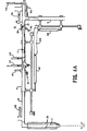
- the tube (2) In the cycle start position, the tube (2) is moved by the directors (22) so as to carry the mouth (20) in correspondence of the zone of accumulation of manufactured products (1) awaiting treatment (fig. 1A) and the respective suction means are activated to operate the removal of at least one manufactured product (1), with the valve (23) disposed in the position of minimal opening of the mouth (20), and by means compressed air at the outlet of the nozzle (21) is carried out the detachment of the manufactured products from the mass (M) adhering to these thus removed by the tube (2).
- the manufactured products of the cluster (M) can spontaneously adhere to each other, due to the specific nature of the material of which they are made up.
- the manufactured products are knitted fabric obtained by son of synthetic nature which tend, in fact, to produce such effect of spontaneous adhesion.
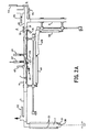
- the valve (23) is placed in the position of maximum opening of the mouth (20) but before, the plate (31) of the station (A) is placed in the position of closing the corresponding portion of the tube (30). (Fig. 2A) so as to determine, in said station (A), the stopping of the manufactured product or of the manufactured products (1) sampled by means of the tube (2).
- the producer (34) is activated to block the manufactured products by means of the body (33) (fig. 2B) passing through the guide (35) of the tube (30).
- the suction is inverted, so as to cause the distention of the manufactured products thus blocked along the common longitudinal axis of the complex of conduits (3, 4, 30) and the carriage (4) is moved in the direction indicated by the arrow F in fig. 3A to allow the search for the end portion of the manufactured product (1) which results further from the above station (A). More precisely, the carriage (4) is moved up to the raising, by any of the sensors (41), of the end or portion of the manufactured product (1) which results more distant from the blocking point of the station (A ).
- the finger (42) associated with the sensor (41) which has raised said end or portion of the manufactured product is actuated so as to compress it on the lower surface of the pad (44), suitably moved towards the manufactured product, which is thus interposed, and thus block it (fig. 3B).
- the finger (42) associated with the sensor (41) which has raised said end or portion of the manufactured product, is actuated so as to compress it on the lower surface of the pad (44), suitably moved towards the manufactured product, which is thus interposed, and thus block it (fig. 3B).
- the movement of the blade (46) is controlled by means of the director (47) and of the plate (48) by means of the director (49).
- the release of the manufactured product (1) is controlled from the grip of the finger (42) and of the buffer (44).
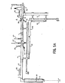
- an internal throttle is produced in the carriage (4) so as to allow only the passage of the finer portion of the manufactured product (1), as well as if the part of the manufactured product which was previously blocked by means of the finger (42) and the buffer (44) is that corresponding to the thinner portion, by effect of the persistent suction towards the discharge station (U) the manufactured product results with the thicker portion already oriented towards this station (U) of the apparatus (FIG.
- the finer portion of the manufactured product results from the outlet station side (U) and the procedure is as follows. After activating the suction in the duct (6) placed between the outlet section (U) and the station (A) (fig. 6A), so as to introduce the finest portion of the manufactured product (1), then said suction is interrupted and the portion of the manufactured product introduced into the duct (6) is blocked to prevent movement thereof; afterwards we suck in the direction of the exit station (U) and we release the manufactured product from the grip of the elements (46) and (48) of the carriage (4).
- the thicker portion of the manufactured product (1) will be turned towards the exit station (U), as desired. Finally, the portion of the manufactured product which has been introduced into the tube (6) is released to allow it to exit through the station (U).
- the manufactured product is a stocking, of the type specially suitable for the manufacture of tights, for the thinner portion of the manufactured product we will hear the bottom part corresponding to the toe and for the thicker portion we will hear the one in tights body match.
- a programmable control unit is used, in itself already known by the technicians of industrial automation and, therefore, not described in detail.
- said tube (6) is of telescopic structure, the movement of which is controlled by a corresponding producer (60) supported by a fixed part (410) of the apparatus.
- the working position of the blade (46) that is to say the distance from its end (461) relative to the corresponding internal wall of the carriage (4), is adjustable by associated screw means (470) to the director rod (47) with limit switch function.
- (AS) is indicated a vacuum cleaner, with (D) a distributor, with (50) and (51) two conduits downstream of the valves (V2) and (V3) respectively, for recovery manufactured products (1) expelled by the apparatus and for their return to the container (M).
- the recovery bells (52,53) are in already known to those skilled in the art.
- the tube (2) can be combined with a optical sensor - not shown for simplification in the figures of the accompanying drawings - near the mouth (20) to raise the presence of manufactured products (1) in the container or heap (M) and in correspondence stop and reverse the directors' course (22) after sample.
- rollers (R ', R'',R'') are provided arranged in an intermediate position between the stations (A) and (B) and each time activated in torque (R ' , R ''; R ', R'').
- rollers (R ', R ") aligned vertically are intended to move the manufactured product, a reduced portion of which is retained in station (A), towards station (B), until all of the fabric of the manufactured product between the station (A) and the photocells (41) In this condition, the element (42) associated with the photocell (41) discovered last.
- a photocell (F) is advantageously provided which, once discovered by the fabric moving towards the station (A), controls the slowing down of the rollers (R ', R ") for dragging the manufactured product , to allow more control on the part of the photocells (41) of the station (B).
- the rollers (R ', R''') horizontally aligned are activated only if it is necessary to send the elastic inside of the conduit (6) for a line of predetermined length for then reversing the aspiration and obtaining the output of the manufactured product through the outlet station (U) with the point facing forward.
- the movement of the rollers (R ', R '') can be controlled by a photocell (FW) placed in correspondence of an arrival position on the duct (6) or also by a timer, not shown in the figure.
- the roller (R ') is mounted so as to be able to move away from the roll (R '') in the event of possible unloading of a manufactured product through the conduit (6).
- a valve (SV) can be provided to section the guide duct of the manufactured products being treated and to obtain a waiting zone (AT) intended for the parking of the manufactured products to be treated thereafter.
- a device called an “anti-twist” per se already known can be provided.
- the container (1) which contains the manufactured products to be treated is advantageously mounted rotating around its own central vertical axis.
Landscapes
- Engineering & Computer Science (AREA)
- Textile Engineering (AREA)
- Eyeglasses (AREA)
- Sewing Machines And Sewing (AREA)
- Manipulator (AREA)
- Knitting Machines (AREA)
Claims (15)
- Vorrichtung zum automatischen Abnehmen eines in Herstellung befindlichen, schlauchförmigen Produktes (1) aus einem flexiblen und elastischen Material, wie zum Beispiel eines Trikotagestrumpfes von einem Haufen (M) oder aus einem Behälter in dem mehrere in Herstellung befindliche Produkte durcheinander angehäuft sind, mit einem Rohr (2), das betriebsmäßig mit einer Ansaugeinrichtung (AS) in Verbindung steht, wobei das in Herstellung befindliche Produkt zwei Endbereiche aufweist, die gleiche oder unterschiedliche Dicken besitzen, und zum Orientiren der Enden in einer vorbestimmten Richtung, dadurch gekennzeichnet, daß die Vorrichtung folgende Bestandteile umfaßtEinrichtungen um durch Ansaugung wenigstens ein derart abgenommenes Produkt (1) zu transportieren, mit zwei horizontalen, ausgerichteten und koaxialen Rohren (3, 30), die einander gegenüberliegende Enden aufweisen und miteinander durch einen rohrförmigen Schlitten (4) verbunden sind, der in gleitender Weise auf den Rohren (3, 30) montiert ist, wobei die Rohre (3, 30, 4) betriebsmäßig mit der Ansaugvorrichtung (AS) verbunden sind und voneinander getrennt entsprechend der Richtung arbeiten, in welcher die Überführung des Produkts (1) erfolgen soll,Einrichtungen (31, 32) zum Festhalten des vordersten Teils wenigstens eines Produktes (1), das in die Rohre (3, 30) angesaugt ist, bis zu einer Haltestation (A) im Bereich des Rohres (30),optische Sensoren (41), die von dem Schlitten (4) getragen werden und gemäß einer im wesentlichen senkrecht zu seiner Bewegungsrichtung verlaufenden Achse ausgerichtet sind, um den Teil des Produktes (1) zu detektieren, der sich am weitesten von der Station (A) entfernt befindet, wenn das Produkt von den Einrichtungen (31, 32) festgehalten und gleichzeitig in der Richtung ausgespannt wird, die der des Ankommens in der Station (A) entgegengesetzt ist, sowieEinrichtungen (42, 43), die betriebsmäßig Sensoren (41) in der Nähe einer Station (B) zugeordnet sind, die im Bereich des Schlittens (4) vorgesehen ist, um das Blockieren des Teils des Produktes (1) durchzuführen, der am weitesten von der Station (A) entfernt ist.
- Vorrichtung nach Anspruch 1, dadurch gekennzeichnet, daß der rohrförmige Schlitten (4) betriebsmäßig mit einem Bewegungsorgan (40) verbunden ist, um ihm die Bewegung längs seiner Achse zu ermöglichen, die mit der der Rohre (3, 30) zusammenfällt.
- Vorrichtung nach Anspruch 1, dadurch gekennzeichnet, daß die Mittel zum Festhalten eines jeden in Herstellung befindlichen Produktes (1) in der Station (A) eine perforierte Platte (31) umfassen, die im Inneren des Elementes (30) angeordnet und an einem festen Punkt angelenkt ist, um ihr unter der Steuerung eines entsprechenden Bewegungsorgans (32) eine Drehung zwischen einer Abfangposition für das Produkt (1) und einer zweiten Position zu ermöglichen, die ein freies Vorbeibewegen des Produktes ermöglicht.
- Vorrichtung nach den Ansprüchen 1 und 3, dadurch gekennzeichnet, daß die Einrichtungen zum Festhalten eines Teils wenigstens eines in Herstellung befindlichen Produktes (1) im Bereich der Station (A) einen stangenförmigen Körper (33) umfassen, der betriebsmäßig mit einem Bewegungsorgan (34) in Verbindung steht und dessen freies Ende dazu bestimmt ist, in der aktiven Stellung auf das in Herstellung befindliche Produkt (1) in Zusammenarbeit mit der Platte (31) einzuwirken, die sich in ihrer Abfangposition befindet oder ansonsten mit der Oberfläche einer Innenwand des rohrförmigen Elementes (30), wobei die Stange (33) durch eine Führungsöffnung (35) hindurch verläuft, die in dem rohrförmigen Element (30) vorgesehen ist, und wobei das betreffende Bewegungsorgan (34) im Bereich einer Wand dieses Elementes (30) befestigt ist.
- Vorrichtung nach Anspruch 1, dadurch gekennzeichnet, daß die Mittel zum Blockieren des Endes des Produktes (1) in der Station (B) in der durch die optischen Sensoren (41) erfaßten Position eine Vielzahl von Fingern (42) umfassen, von denen jeder einem entsprechenden Sensor (41) zugeordnet und betriebsmäßig mit einer entsprechenden Bewegungsvorrichtung verbunden ist, wobei jeder Finger (42) an einem festen Punkt angelenkt ist, um dadurch eine gesteuerte Drehung des betreffenden Sensors (41) mit Hilfe des entsprechenden Bewegungsorgans (43) zu ermöglichen und das freie Ende in Berührung mit einem Pfropfen (44) in Berührung zu bringen, der auf der gegenüberliegenden Seite angeordnet und betriebsmäßig mit einem entsprechenden Bewegungsorgan (45) verbunden ist, wobei die Finger (42) mit dem entsprechenden Bewegungsorgan (43) und der Pfropfen (44) mit dem entsprechenden Bewegungsorgan (43) mit dem Schlitten (4) fest verbunden sind.
- Vorrichtung nach Anspruch 1, dadurch gekennzeichnet, daß sie Einrichtungen umfaßt, die dazu dienen, das eventuelle Vorhandensein des dicksten Teils des in Herstellung befindlichen Produktes (1) in der Nähe der Station (B) festzustellen, mit einer Klinge (46), die so angeordnet ist, daß sie sich durch einen entsprechenden Schlitz des Schlittens (4) senkrecht zur Bewegungsachse des letzteren stromabwärts von den optischen Einrichtungen (41) erstreckt und die einem entsprechenden Bewegungsorgan (47) betriebsmäßig zugeordnet ist, um es in gesteuerter Weise zu ermöglichen, das betreffende freie Ende (46↑) in einem vorbestimmten Abstand von der entsprechenden, dem Schlitten (4) gegenüberliegenden Innenwand zu positionieren, wobei dieser Abstand günstigerweise so wählbar und einstellbar ist, daß er das Hindurchgehen des Teils des in Herstellung befindlichen Produktes (1) mit der kleineren Dicke ermöglicht und den Teil mit der größeren Dicke festhält, wobei die Klinge (46) und das zugehörige Bewegungsorgan (47) mit dem Schlitten (4) fest verbunden sind.
- Vorrichtung nach Anspruch 6, dadurch gekennzeichnet, daß sie eine zweite perforierte Platte (48) umfaßt, die einem entsprechenden Bewegungsorgan (49) betriebsmäßig zugeordnet ist, um in gesteuerter Weise einen entsprechenden Teils des Produkts (1) abzufangen.
- Vorrichtung nach Anspruch 1, dadurch gekennzeichnet, daß sie Mittel zum eventuellen Umdrehen der Orientierung des Produktes (1) mit wenigstens einem Rohr (6) umfaßt, das mit dem Rohr (30) verbunden und betriebsmäßig mit der pneumatischen Ansaugeinrichtung (AS) verbunden ist, um eine Bewegung des Produktes (1) in seinem Inneren zu ermöglichen.
- Vorrichtung nach Anspruch 1, dadurch gekennzeichnet, daß die Mündung (20) des Rohrs (2) einer Düse (21) zugeordnet ist, um unter Druck stehende Luft im Bereich der Abnahmezone des Produktes (1) von dem Haufen (M) einzublasen und auf diese Weise die Produkte freizugeben, die durch andere Produkte angehoben werden, an denen sie möglicherweise haften.
- Vorrichtung nach Anspruch 1, dadurch gekennzeichnet, daß das Rohr (2) eine teleskopartige Struktur besitzt und daß seine Bewegung durch wenigstens ein Bewegungsorgan (22) gesteuert wird.
- Vorrichtung nach Anspruch 1, dadurch gekennzeichnet, daß das Rohr (2) im Bereich seiner Mündung (20) mit einem Schieber (23) versehen ist, der in gesteuerter Weise die Öffnung derart verkleinem kann, daß in der Phase des Abnehmens des Produktes (1) die Öffnung möglichst klein gemacht wird, um einen möglichst kleinen Teil des Produktes (1) einzulassen, und daß nach diesem Vorgang die Öffnung maximiert wird, um ein schnelles Hindurchtreten des Produktes (1) oder von Produkten durch das Rohr (2) aufgrund der entsprechende Ansaugung zu ermöglichen.
- Vorrichtung nach Anspruch 8, dadurch gekennzeichnet, daß das Rohr (6) eine Teleskopstruktur besitzt und daß seine Bewegung durch ein entsprechendes Bewegungsorgan (60) gesteuert wird, das von einem festen Teil (410) der Vorrichtung getragen wird.
- Vorrichtung nach Anspruch 1, dadurch gekennzeichnet, daß die Mittel zum Abnehmen des Produktes (1) mit wenigstens einem optischen Sensor zu ihrer Erkennung versehen sind.
- Vorrichtung nach Anspruch 6, dadurch gekennzeichnet, daß die Klinge (46) einem optischen Sensor (460) zugeordnet ist, der dazu dient, das eventuelle Vorhandensein eines dicken Teils des Produktes (1) zu erkennen, der in der Station (B) festgehalten wird.
- Vorrichtung nach Anspruch 6, dadurch gekennzeichnet, daß die Arbeitsstellung der Klinge (46), das heißt der Abstand ihres Endes (461) von der entsprechenden Innenwand des Schlittens (4) durch eine Schraubeinrichtung (470) einstellbar ist, die für die Stange der Bewegungsvorrichtung (47) als Bewegungsbahn-endanschlag dient.
Applications Claiming Priority (2)
| Application Number | Priority Date | Filing Date | Title |
|---|---|---|---|
| ITFI960163 | 1996-07-09 | ||
| IT96FI000163A IT1286671B1 (it) | 1996-07-09 | 1996-07-09 | Metodo ed apparecchiatura per il prelievo e la movimentazione di manufatti tubolari |
Publications (2)
| Publication Number | Publication Date |
|---|---|
| EP0818570A1 EP0818570A1 (de) | 1998-01-14 |
| EP0818570B1 true EP0818570B1 (de) | 2003-05-14 |
Family
ID=11351753
Family Applications (1)
| Application Number | Title | Priority Date | Filing Date |
|---|---|---|---|
| EP97830340A Expired - Lifetime EP0818570B1 (de) | 1996-07-09 | 1997-07-07 | Vorrichtung zur Aufnahme und Weiterbewegung von schlauchformigen Gegenständen |
Country Status (5)
| Country | Link |
|---|---|
| US (1) | US5884822A (de) |
| EP (1) | EP0818570B1 (de) |
| JP (1) | JPH1072748A (de) |
| DE (1) | DE69721901D1 (de) |
| IT (1) | IT1286671B1 (de) |
Families Citing this family (11)
| Publication number | Priority date | Publication date | Assignee | Title |
|---|---|---|---|---|
| US6155466A (en) * | 1997-06-02 | 2000-12-05 | Matec S.P.A. | Apparatus for stretching apart one end of a tubular article |
| IT1308256B1 (it) | 1999-03-23 | 2001-12-10 | Matec Spa | Dispositivo per l'orientamento automatico di manufatti tubolari comecalze e articoli similari. |
| IT1314867B1 (it) * | 2000-07-21 | 2003-01-16 | Matec Spa | Metodo per rilevare l'orientamento di un manufatto tessile presentante due estremita' differenti, apparecchiatura per attuare il suddetto |
| US6820497B2 (en) | 2001-01-03 | 2004-11-23 | Threadbear, Llc | Method and apparatus for detecting and controlling orientation of articles for further processing |
| ITPI20010021A1 (it) * | 2001-03-21 | 2002-09-21 | S R A S R L | Metodo ed apparecchiatura per l'orientamento longitudinale di articoli di calzetteria |
| DE10307416A1 (de) | 2002-02-20 | 2003-08-21 | Kannegiesser H Gmbh Co | Verfahren und Vorrichtung zum pneumatischen Fördern von vorzugsweise Wäsche |
| ITFI20020106A1 (it) * | 2002-06-18 | 2003-12-18 | Matec Spa | Dispositivo e metodo per rilevare l'orientamento di manufatti come calze e calzini da uomo |
| US7044071B2 (en) * | 2003-01-24 | 2006-05-16 | B.B. & S Knitting Consultants | Apparatus and method for automatically orienting hosiery articles for closing toe ends thereof |
| MXPA06011935A (es) * | 2004-04-16 | 2007-04-13 | Golden Lady Co Spa | Maquina para manejar articulos tejidos tubulares, tal como calcetines o similares. |
| WO2007020667A1 (en) * | 2005-08-19 | 2007-02-22 | Golden Lady Company S.P.A. | Device and method for handling tubular knitted articles, such as stockings and socks or the like |
| ITFI20060118A1 (it) * | 2006-05-19 | 2007-11-20 | Golden Lady Co Spa | Metodo e dispositivo per discriminare l'una rispetto all'altra due estremita' di un manufatto |
Family Cites Families (13)
| Publication number | Priority date | Publication date | Assignee | Title |
|---|---|---|---|---|
| FR1523778A (fr) * | 1967-05-19 | 1968-05-03 | Feinstrumpfwerke Esda Veb | Dispositif pour le retournage pneumatique d'articles bruts tubulaires, par exemple debas de femme de tricotage circulaire |
| DE1907167A1 (de) * | 1968-03-09 | 1969-10-02 | Arrigo Micheletti | Pneumatische Vorrichtung zum Ausstrecken von Struempfen und dergleichen Warenstuecken |
| US3696942A (en) * | 1970-09-30 | 1972-10-10 | Usm Corp | Means for transferring successive flexible work pieces |
| US4539924A (en) * | 1981-08-28 | 1985-09-10 | Consolidated Foods Corporation | Loading system for a toe closing assembly |
| US5040475A (en) * | 1989-01-28 | 1991-08-20 | Sara Lee Corporation | Material handling system |
| US5165355A (en) * | 1991-03-26 | 1992-11-24 | Sara Lee Corporation | Method and apparatus for handling hosiery blanks |
| IT1250168B (it) * | 1991-06-03 | 1995-04-03 | Metalprogetti Snc | Impianto aereo di trasporto a nastro, in grado di smistare ordinatamente i capi che siano caricati su di esso alla rinfusa. |
| IT1257118B (it) * | 1992-10-01 | 1996-01-05 | Rosso Ind Spa In Persona Dell | Dispositivo abbinabile ad una rovesciacalze automatica, atto a separare senza interventi manuali calze completamente rovesciate da quelle solo parzialmente rovesciate. |
| IT1265876B1 (it) * | 1993-06-25 | 1996-12-12 | Solis Srl | Metodo e dispositivo per disporre due manufatti tubolari in una posizione prestabilita su di un corrispondente supporto |
| US5544603A (en) * | 1994-04-05 | 1996-08-13 | Monarch Knitting Machinery Corporation | Apparatus for handling flexible objects |
| US5456392A (en) * | 1994-06-01 | 1995-10-10 | Majors; James W. | Sock sorting device |
| GB9507510D0 (en) * | 1995-04-11 | 1995-05-31 | Detexomat Machinery Ltd | Method & apparatus for manipulating a length of flexible material |
| IT1283271B1 (it) * | 1996-03-18 | 1998-04-16 | Essedue S R L | Dispositivo stenditore di calze ad alimentazione pneumatica, utilizzabile con impianti di trasporto pneumatico di calze ad |
-
1996
- 1996-07-09 IT IT96FI000163A patent/IT1286671B1/it active IP Right Grant
-
1997
- 1997-07-07 EP EP97830340A patent/EP0818570B1/de not_active Expired - Lifetime
- 1997-07-07 DE DE69721901T patent/DE69721901D1/de not_active Expired - Lifetime
- 1997-07-08 JP JP9197793A patent/JPH1072748A/ja active Pending
- 1997-07-08 US US08/889,633 patent/US5884822A/en not_active Expired - Fee Related
Also Published As
| Publication number | Publication date |
|---|---|
| JPH1072748A (ja) | 1998-03-17 |
| ITFI960163A1 (it) | 1998-01-09 |
| DE69721901D1 (de) | 2003-06-18 |
| IT1286671B1 (it) | 1998-07-15 |
| EP0818570A1 (de) | 1998-01-14 |
| US5884822A (en) | 1999-03-23 |
Similar Documents
| Publication | Publication Date | Title |
|---|---|---|
| EP0818570A1 (de) | Verfahren und Vorrichtung zur Aufnahme und Weiterbewegung von schlauchformigen Gegenständen | |
| FR2621599A1 (fr) | Procede et dispositif de nettoyage et d'ouverture d'une matiere fibreuse se presentant sous la forme de flocons, par exemple du coton | |
| FR2502594A1 (fr) | Dispositif pour changer la direction de transport d'objets individuels | |
| EP0430900A2 (de) | Verfahren und Vorrichtung zum Umwenden von Socken ausserhalb der dazugehörigen Behandlungsmaschine | |
| CH634205A5 (fr) | Dispositif de prelevement automatique d'un echantillon de filtre ou de cigarette. | |
| EP2051918B1 (de) | Vorrichtung zum umdrehen von behältern | |
| FR3106586A1 (fr) | Dispositif permettant d'alimenter automatiquement sans discontinuer un Robot d'enfilage des chaussettes orientées dans le bon sens sur une formeuse par des bacs remplis de chaussettes en vrac | |
| EP0534915A1 (de) | Verfahren zum automatischen Zusammennähen zweier Strümpfe zu einer Strumphose und Maschine zur Durchführung des Verfahrens | |
| EP0630999B1 (de) | Verfahren und Vorrichtung, um zwei schlauchförmige Produkte auf einer vorbestimmten Position auf einem entsprechenden Träger anzuordnen | |
| CA2429859A1 (fr) | Procede de lacage selectif de fils sur des preformes textiles multidimensionnelles et dispositif pour sa mise en oeuvre | |
| FR2467902A1 (fr) | Dispositif pour la mise automatique en position d'une piece de vetement en vue de l'execution d'une couture | |
| EP0584050B1 (de) | Verfahren und Vorrichtung zum Überführen einer Strumpfhose von einer Strumpfhosen-Nähmaschine zu einer zehenschliessenden Nähmaschine | |
| FR2615497A1 (fr) | Dispositif prehenseur de tissu et notamment dispositif manipulateur de manche | |
| EP1222845B1 (de) | Verfahren zum Trennen eckiger Setzlinge, Gerät zum Ausführen des Verfahrens und Pflanzmaschine mit einem solchen Gerät zum Pflanzen von Setzlingen | |
| FR2589464A1 (fr) | Appareil pour la decoration automatique, par liseres ou par frises, d'articles en ceramique | |
| WO2005054102A1 (fr) | Dispositif de prelevement automatique pour le changement de bobine dans des machines pour la production de bobines de papier et similaires | |
| WO2001096649A1 (fr) | Machine de blanchisserie industrielle dite 'engageuse' | |
| FR2472532A1 (fr) | Machine pour enrouler du fil sur des bobines | |
| FR2801168A1 (fr) | Procede pour separer des mottes cubiques, dispositif pour la mise en oeuvre du procede et machine de plantation de plants en mottes comportant un tel dispositif | |
| EP0887453A1 (de) | Vorrichtung und Verfahren zum Positionieren von Textilartikeln | |
| BE458290A (de) | ||
| EP1090172B1 (de) | Vorrichtung zum aussondern von verunreinigungen aus einem sich bewegenden faservlies und karde mit solch einer vorrichtung | |
| EP0097212A1 (de) | Werkstückzufuhreinrichtung für Nähmaschinen | |
| FR2651804A1 (fr) | Appareil pour traiter une pile de vetements en vue de leur couture. | |
| JPH0241181Y2 (de) |
Legal Events
| Date | Code | Title | Description |
|---|---|---|---|
| PUAI | Public reference made under article 153(3) epc to a published international application that has entered the european phase |
Free format text: ORIGINAL CODE: 0009012 |
|
| AK | Designated contracting states |
Kind code of ref document: A1 Designated state(s): DE FR GB IT |
|
| AX | Request for extension of the european patent |
Free format text: AL;LT;LV;RO;SI |
|
| 17P | Request for examination filed |
Effective date: 19980401 |
|
| AKX | Designation fees paid |
Free format text: DE FR GB IT |
|
| RBV | Designated contracting states (corrected) |
Designated state(s): DE FR GB IT |
|
| RAP1 | Party data changed (applicant data changed or rights of an application transferred) |
Owner name: MATEC S.P.A. |
|
| 17Q | First examination report despatched |
Effective date: 20000308 |
|
| GRAH | Despatch of communication of intention to grant a patent |
Free format text: ORIGINAL CODE: EPIDOS IGRA |
|
| RTI1 | Title (correction) |
Free format text: APPARATUS FOR COLLECTING AND MOVING TUBULAR PRODUCTS |
|
| RTI1 | Title (correction) |
Free format text: APPARATUS FOR COLLECTING AND MOVING TUBULAR PRODUCTS |
|
| GRAH | Despatch of communication of intention to grant a patent |
Free format text: ORIGINAL CODE: EPIDOS IGRA |
|
| GRAH | Despatch of communication of intention to grant a patent |
Free format text: ORIGINAL CODE: EPIDOS IGRA |
|
| GRAA | (expected) grant |
Free format text: ORIGINAL CODE: 0009210 |
|
| AK | Designated contracting states |
Designated state(s): DE FR GB IT |
|
| PG25 | Lapsed in a contracting state [announced via postgrant information from national office to epo] |
Ref country code: IT Free format text: LAPSE BECAUSE OF FAILURE TO SUBMIT A TRANSLATION OF THE DESCRIPTION OR TO PAY THE FEE WITHIN THE PRESCRIBED TIME-LIMIT;WARNING: LAPSES OF ITALIAN PATENTS WITH EFFECTIVE DATE BEFORE 2007 MAY HAVE OCCURRED AT ANY TIME BEFORE 2007. THE CORRECT EFFECTIVE DATE MAY BE DIFFERENT FROM THE ONE RECORDED. Effective date: 20030514 Ref country code: GB Free format text: LAPSE BECAUSE OF FAILURE TO SUBMIT A TRANSLATION OF THE DESCRIPTION OR TO PAY THE FEE WITHIN THE PRESCRIBED TIME-LIMIT Effective date: 20030514 |
|
| REG | Reference to a national code |
Ref country code: GB Ref legal event code: FG4D Free format text: NOT ENGLISH |
|
| REF | Corresponds to: |
Ref document number: 69721901 Country of ref document: DE Date of ref document: 20030618 Kind code of ref document: P |
|
| PG25 | Lapsed in a contracting state [announced via postgrant information from national office to epo] |
Ref country code: DE Free format text: LAPSE BECAUSE OF FAILURE TO SUBMIT A TRANSLATION OF THE DESCRIPTION OR TO PAY THE FEE WITHIN THE PRESCRIBED TIME-LIMIT Effective date: 20030815 |
|
| GBV | Gb: ep patent (uk) treated as always having been void in accordance with gb section 77(7)/1977 [no translation filed] |
Effective date: 20030514 |
|
| PLBE | No opposition filed within time limit |
Free format text: ORIGINAL CODE: 0009261 |
|
| STAA | Information on the status of an ep patent application or granted ep patent |
Free format text: STATUS: NO OPPOSITION FILED WITHIN TIME LIMIT |
|
| PG25 | Lapsed in a contracting state [announced via postgrant information from national office to epo] |
Ref country code: FR Free format text: LAPSE BECAUSE OF NON-PAYMENT OF DUE FEES Effective date: 20040331 |
|
| REG | Reference to a national code |
Ref country code: FR Ref legal event code: ST |
|
| 26N | No opposition filed |
Effective date: 20040217 |