EP0817656B1 - Hochbelastbarer führungsdraht aus schlauchförmigen nitinol mit übergangselementen aus kunststoff - Google Patents
Hochbelastbarer führungsdraht aus schlauchförmigen nitinol mit übergangselementen aus kunststoff Download PDFInfo
- Publication number
- EP0817656B1 EP0817656B1 EP96912501A EP96912501A EP0817656B1 EP 0817656 B1 EP0817656 B1 EP 0817656B1 EP 96912501 A EP96912501 A EP 96912501A EP 96912501 A EP96912501 A EP 96912501A EP 0817656 B1 EP0817656 B1 EP 0817656B1
- Authority
- EP
- European Patent Office
- Prior art keywords
- guidewire
- tube
- distal end
- plug
- plug segment
- Prior art date
- Legal status (The legal status is an assumption and is not a legal conclusion. Google has not performed a legal analysis and makes no representation as to the accuracy of the status listed.)
- Expired - Lifetime
Links
Images
Classifications
-
- A—HUMAN NECESSITIES
- A61—MEDICAL OR VETERINARY SCIENCE; HYGIENE
- A61M—DEVICES FOR INTRODUCING MEDIA INTO, OR ONTO, THE BODY; DEVICES FOR TRANSDUCING BODY MEDIA OR FOR TAKING MEDIA FROM THE BODY; DEVICES FOR PRODUCING OR ENDING SLEEP OR STUPOR
- A61M25/00—Catheters; Hollow probes
- A61M25/01—Introducing, guiding, advancing, emplacing or holding catheters
- A61M25/09—Guide wires
- A61M2025/09058—Basic structures of guide wires
- A61M2025/09083—Basic structures of guide wires having a coil around a core
Definitions
- the present invention relates to guidewires, and more particularly, to high support guidewires with a flexible tube at the distal end.
- a guidewire can be used in PTCA procedures such as balloon angioplasty, atherectomy, stent implantation procedures, or radiology procedures.
- PTCA percutaneous transluminal coronary angioplasty
- This procedure can be used, for example, to reduce arterial build-up of cholesterol fats or atherosclerotic plaque.
- a guidewire is steered through the vascular system to the site of therapy.
- a guiding catheter for example, can then be advanced over the guidewire and a balloon catheter advanced within the guiding catheter over the guidewire.
- the balloon at the distal end of the catheter is inflated causing the site of the stenosis to widen.
- the original catheter can then be withdrawn and a catheter of a different size or another device such as an atherectomy device can be inserted.
- a tapered stainless steel core wire has a platinum spring coil wound around the tapered distal end of the core wire.
- the tapered area of the core wire is called the transition segment. The longer the tapered transition segment, the more flexible the guidewire.
- a blunt tip is typically welded to the distal end of the guidewire to reduce trauma to the blood vessel.
- Support refers to a guidewire's ability to provide a strong "platform" or track for the catheter to move over as it is crossing the lesion. Support becomes crucial when the lesion is tight. Catheters are soft and rely heavily on the support provided by the guidewire.
- the spring coil is typically used to provide device support and maintain a consistent guidewire outer diameter. If the outer diameter of the guidewire is reduced, it will exert more force per unit area and may result in cutting through the blood vessel rather than tracking through the bends in the vessels. Increasing core wire diameter also assists in providing enhanced support.
- the spring coil wire is wound into a coil and placed over the core wire. The spring coil proximal end is difficult to attach to the core wire.
- a typical spring coil is approximately 0.05mm (.002 inches) in diameter thereby providing a very small area with which to attach to the core wire.
- Spring coil guidewire construction has been known in the art for many years. An early example of such guidewire construction includes U.S.P.N. 3,789,841 for a "Disposable Guide Wire" to Antoshkiw .
- Transition refers to areas of changing diameter along the guidewire.
- a smooth transition gives the guidewire the ability to follow itself smoothly around vascular bends. If a stiffer portion of the guidewire behind the flexible tip does not follow the tip around vascular bends, the tip position may be lost.
- a guidewire with poor or rough transition will show elbows or bends in the vascular curves. Without smooth transitions a guidewire will not corner smoothly. Smooth transitions also facilitate the tracking of the balloon catheter over the wire when crossing the lesion.
- U.S. Patent No. 4,884,579 to Engelson for "Catheter Guidewire” discloses a guidewire with proximal, intermediate and distal sections.
- the intermediate section has greater lubricity than the adjacent proximal and distal sections.
- the greater frictional coefficient in the distal end segment acts to anchor the end of the wire in a branch vessel when the guide wire has been advanced across the sharp-bend vessel junction.
- the distal segment of the core wire is encased in a polymer tube having a series of annular grooves to provide increased tube flexibility as well as greater frictional coefficient.
- Elastomers and shape memory materials have been used in the catheter industry to promote elasticity and to promote tips that will return to a preformed curve after flexing.
- Super-elastic guidewires are known in the art, as for example, U.S. Patent No. 4,925,445, to Sakamoto et al. for "Guide Wire for Catheter” which discloses a guidewire with at least portions of the inner core formed of the super-elastic metallic member.
- U.S. Patent No. 5,067,489 to Lind for "Flexible Guide with Safety Tip” discloses an elongate, helically wound coil and an elongate flexible metal core of shape memory alloy.
- Catheter Guidewire with Pseudo Elastic Shape Memory Alloy discloses a catheter guide wire comprising a solid core wire of Ti-Ni shape memory alloy and an outer jacket covering the core wire.
- the jacket is made of any one of synthetic resins such as polyethylene, polyvinyl chloride, polyester, polypropylene, polyamide, polyurethane, polystyrene, fluoride resin, silicone rubber, and other elastomers.
- synthetic resins such as polyethylene, polyvinyl chloride, polyester, polypropylene, polyamide, polyurethane, polystyrene, fluoride resin, silicone rubber, and other elastomers.
- 5,243,996 to Hall for "Small-Diameter Superelastic Wire Guide” discloses a mandrel of metallic superelastic material, such as nitinol having a smoothly rounded tip attached to the distal tip of the mandrel and a coil attached at the distal region of the mandrel, the coil coaxially surrounding a portion of the distal region.
- a drawback of spring coils as currently used in guidewires is that their indented surface may not pass through tight lesions effectively and may catch on devices being passed over them such as devices with cutting mechanisms. Another disadvantage is that they may provide too much flexibility for some devices to properly track over. Additionally, the spring coil is difficult to manufacture because it requires the wire to be helically wound with a uniform outer diameter, then placed over the core wire and welded thereto. The spring coil is also prone to separation where it attaches.
- An object of the invention is to eliminate the need of a guidewire spring coil while maintaining a uniform shaft outer diameter and providing sufficient support for more difficult PTCA procedures such as total occlusions, atherectomy, Rotoblator ® (a registered trademark of Heart Technology, Inc.) and stent delivery. Another object of the invention is to provide steerability for wire placement. Yet another object of the invention is to avoid attachment weakness at the location where the spring coil would have attached to the core wire.
- a guidewire for use in a catheter comprising:
- the tube may be formed of a super-elastic metallic member or formed from a synthetic resin.
- the tube wall thickness is preferably between 0.05mm and 0.125mm (.002 inches and .005 inches).
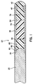
- FIG. 1 is an enlarged sectional view of a catheter guidewire according to the invention.
- Prior art guidewires are currently constructed with a spring coil over the tapered distal end of the core wire to increase flexibility while maintaining a constant shaft outer diameter.
- a radiused blunt tip is soldered to the distal end of the core wire and spring coil.
- the preferred guidewire 20 is a standard length of 175 - 310 cm long.
- the guidewire 20 is constructed using a tube 30 which can be made of an elastomer or an alloy which is highly flexible without permanent deformation such as a shape memory alloy.
- the tube 30 can be approximately 10 cm to 40 cm long, preferably 30 cm which is the average length from the coronary vessel to the aortic arch.
- the tube 30 can preferably be made of a shape memory alloy such as nitinol manufactured by Raychem or Forukawa.
- a preferred embodiment uses NiTi 49 - 51 atom % Ni.
- Shape memory alloys allow one to deform the alloy at a lower temperature with fairly low force and then with merely the application of heat, the material will exert a very strong force as it attempts to regain its previous shape.
- a useful shape memory alloy property includes an exceptional superelastic springiness if one deforms it at a temperature slightly above the transformation temperature. Shape memory alloys exhibit a very soft, energy absorbing behavior if used just below that temperature.
- NiTi has a much lower effective modulus than stainless steel.
- the NiTi family is the most commercially attractive system.
- the NiTi alloy has constituents which are not prohibitively expensive, can be fabricated with existing metalworking techniques and have greater shape memory strain (up to 8%) than other alloys.
- shape memory alloy list supra many contain expensive or exotic elements which are not as commercially attractive as NiTi.
- Tube 30 can also be made of a synthetic resin elastomer such as any one of polyethylene, polyvinyl chloride, polyester, polypropylene, polyamide, polyurethane, polystyrene, and other elastomers.
- a fluoropolymer can also be used such as TEFLON® from E.I. Du Pont de Nemours & Company, Wilmington, Delaware.
- TEFLON® is a form of polytetrafluoroethylene (PTFE).
- Elastomers are lower cost then shape memory alloys. Shape memory alloys, however, provide more rigidity for better support than most of the elastomers.
- the tube 30 is supported by a distally tapering core wire 25.
- the core wire 25 can be constructed of stainless steel.
- the tube 30 wall thickness varies depending of the size guidewire 20 used. The bigger the guidewire 20, the thicker the tube 30 must be to provide support. For example, a tube 30 wall thickness of 0.5mm (.002 inches) could be used for 0.25mm (.010 inch) guidewires. A tube 30 wall thickness of 0.125mm (.005 inches) could be used for 10mm (.40 inch) guidewires. The preferred tube 30 wall thickness is 0.0625mm (.0025 inches).
- a constant shaft outer diameter is maintained throughout the tube 30 by step grinding the distal end of the tube to coincide with the core wire tapered step 60.
- a standard 0.35mm (.014 inch) guidewire with a 30 cm tube 30 An example of a preferred embodiment would contain the following dimensions.
- the proximal end of the guidewire 20 body would have a substantially uniform diameter of 0.35mm (.014 inches).
- the distal end of the core wire 25 would be ground over a length of 5 mm to tapered step 60 with a distal diameter of 0.225mm (.009 inches).
- the distal end of the core wire 25 would be formed into a full radius 80 by a means such as grinding.
- the 5 mm long tapered step 60 is advantageous because it provides a large surface area with which to bond the tube 30 to the core wire 25.
- the hollow portions of tube 30 can be plugged with segments of varying durometer plastic segments to create progressively decreasing stiffness toward the distal end of tube 30.
- Overall stiffness or floppiness can be achieved for different applications. For example, stiffer segments overall would be used for difficult PTCA procedures such as total occlusions, atherectomy, Rotoblator ® (a registered trademark of Heart Technology, Inc.) and stent delivery. Floppier segments overall could be used for traversing especially tight lesions.
- the hollow portions of tube 30 can be plugged with one or more segments of varying durometer plastic such as a synthetic resin elastomer such as any one of polyethylene, polyvinyl chloride, polyester, polypropylene, polyamide, polyurethane, polystyrene, and other elastomers.
- the proximal end of the proximal most plug segment will be affixed to the radiused distal end 80 of the core wire.
- the distal most plug segment will be affixed to the tube 30 distal end by an adhesive bond or by a molding process. Adhesives such as cyanoacrylates or epoxy may be used. Those skilled in the art would recognize that any biocompatible adhesive would be satisfactory.
- the plastic plugs will be molded together after being inserted into the tube 30. Filling the tube 30 with a flexible material will render the tube 30 more kink resistant.
- An example of a preferred embodiment would include three plugs of varying durometer plastic. Those skilled in the art would recognize that other numbers of plugs could be used.
- An acceptable three plug configuration includes the following combination of plug hardnesses and lengths.
- a material of Shore 75 D can be used for the approximately 10 cm long high durometer plug 65.
- a material of Shore 55 D can be used for the approximately 20 cm long medium durometer plug 70.
- a material of Shore 35 D can be used for the approximately 5 cm long low durometer plug 75. Procedures requiring high overall stiffness could be implemented using a material of a Shore 100 D for the approximately 20 cm long high durometer plug 65, a Shore 75 D material for the approximately 10 cm long medium durometer plug 70 and a Shore 55 D material approximately 3 cm long for the low durometer plug 75.
- Procedures requiring low overall stiffness could be implemented using a Shore 55 D material for the approximately 10 cm long high durometer plug 65, a Shore 40 D material for the approximately 10 cm long medium durometer plug 70, and a Shore 25 D material for the 15 cm long low durometer plug 75.
- the proximal end of the tube 30 is affixed to the core wire 25 with an adhesive 35 at the proximal end of the first tapered step 60.
- Adhesives such as cyanoacrylates or epoxy may be used for joining the tube 30 to the core wire 25.
- cyanoacrylates or epoxy may be used for joining the tube 30 to the core wire 25.
- Any biocompatible adhesive would be satisfactory.
- the present invention avoids the spring coil proximal end attachment problems of the prior art.
- a typical spring coil is approximately 0.05mm (.002 inches) in diameter thereby providing a very small area with which to attach to the core wire.
- the tube 30 of the present invention provides a 360 degree area of attachment to the core wire 25. The larger surface area provides for a more reliable attachment.
- a tip 40 is formed out of the plastic material extending from the distal end of the low durometer plug 75. Tip 40 is radiused for an atraumatic tip.
- a radiopaque marker band 45 can be placed in the distal inner lumen of the tube 30 approximately 1 - 2 cm from the tip 40 enabling the physician to visualize the progress of the tip 40 under fluoroscopy.
- the marker band 45 can be attached by heat bonding or with an adhesive such as epoxy. Alternatively, having two radiopaque areas would give the physician a sense of scale.
- the medium durometer plug 70 or the low durometer plug 75 could be made of multiple segments with one of the segments made of plastic loaded with radiopaque fillings. Alternatively, either the medium durometer plug 70 or the low durometer plug 75 could be entirely made of plastic loaded with radiopaque fillings.
- the guidewire 20 is coated with a lubricous coating 50 to enhance the movement of devices over it.
- the guidewire can be coated with a silicone oil or a hydrophilic coating.
- Silicone is that it is inexpensive and easy to apply.
- the advantage of a hydrophilic coating is that it absorbs moisture and becomes slippery when inserted into the blood stream.
Landscapes
- Health & Medical Sciences (AREA)
- Life Sciences & Earth Sciences (AREA)
- Biophysics (AREA)
- Pulmonology (AREA)
- Engineering & Computer Science (AREA)
- Anesthesiology (AREA)
- Biomedical Technology (AREA)
- Heart & Thoracic Surgery (AREA)
- Hematology (AREA)
- Animal Behavior & Ethology (AREA)
- General Health & Medical Sciences (AREA)
- Public Health (AREA)
- Veterinary Medicine (AREA)
- Materials For Medical Uses (AREA)
- Media Introduction/Drainage Providing Device (AREA)
Claims (17)
- Führungsdraht zur Verwendung in einem Katheter, umfassendeinen länglichen Kerndraht (25) mit einem gleichmäßigen Außendurchmesser, einem proximalen und einem distalen Ende,ein einen Rohrraum definierendes längliches Rohr (30), das den gleichen Außendurchmesser wie der Kerndraht (25) sowie ein proximales und ein distales Ende hat, wobei das proximale Ende des Rohrs (30) am distalen Ende des Kerndrahtes (25) befestigt ist und das Rohr (30) eine glatte Außenfläche aufweist, undeiner glatt verrundeten distalen Spitze (40), die über das distale Ende des Rohrs (30) hinausragt und an diesem befestigt ist,
dadurch gekennzeichnet, daß in dem Rohrraum ein oder mehrere Stopfensegmente (65, 70, 75) untergebracht sind, die alle über ihre gesamte Länge den gleichen gleichmäßigen Außendurchmesser aufweisen und deren jedes ein proximales und ein distales Ende hat, wobei jedes Stopfensegment (65, 70, 75) eine geringere Steifigkeit hat als der Kerndraht (25) und als das jeweils proximal vorhergehende Stopfensegment (65, 70, 75), wobei das proximale Ende des am weitesten proximal gelegenen Stopfensegments (65) am distalen Ende des Kerndrahtes (25) und das distale Ende des Rohrs (30) an dem am weitesten distal gelegenen Stopfensegment (75) befestigt ist. - Führungsdraht nach Anspruch 1, wobei sich der Kerndraht (25) in Richtung des distalen Endes verjüngt.
- Führungsdraht nach Anspruch 1, wobei das distale Ende des Kerndrahtes (25) einen kugelförmigen Vollradius bildet.
- Führungsdraht nach einem der Ansprüche 1 bis 3, wobei das Rohr (30) über seine gesamte Länge einen konstanten Außendurchmesser hat.
- Führungsdraht nach einem der vorhergehenden Ansprüche, wobei das Rohr (30) aus einem Elastomer der aus Polyethylen, Polyvinlychlorid, Polyester, Polypropylen, Polyamid, Polyurethan, Polystyrol und Polytetrafluorethylen bestehenden Kunstharzgruppe gebildet ist.
- Führungsdraht nach einem der Ansprüche 1 bis 4, wobei das Rohr aus einem superelastischen Metallmaterial gebildet ist.
- Führungsdraht nach Anspruch 6, wobei das Rohr (30) aus einem superelastischen Metallelement gebildet ist, das eine aus den folgenden Gruppen ausgewählte Legierung enthält: NiTi-Legierung, die im wesentlichen aus 49 bis 58 Atom-% Ni, Rest im wesentlichen Ti besteht, CuZn-Legierung, die im wesentlichen aus 38,5 bis 41,5 Gew-% Zn, Rest im wesentlichen Cu besteht, CuZnX, im wesentlichen bestehend aus wenigen Gew-% X (mit X=Si, Sn, Al), NiAl-Legierung, im wesentlichen bestehend aus 36 bis 38 Atom-% Al, Rest im wesentlichen Ni, CuAlNi mit 14 bis 14,5 Gew-% Al, 3 bis 45 Gew-% Ni, MnCu mit 5 bis 35 Atom-% Cu, FeMnSi mit 32 Gew-% Mn und 6 Gew-% Si.
- Führungsdraht nach einem der vorhergehenden Ansprüche, wobei das Rohr (30) eine Wandstärke zwischen etwa 0,5 mm und 0,125 mm (0,002 inch und 0,005 inch) hat.
- Führungsdraht nach einem der vorhergehenden Ansprüche, wobei die Stopfensegmente (65, 70, 75) dadurch aneinander befestigt sind, daß das distale Ende des proximal vorhergehenden Stopfensegments an das proximale Ende des distal folgenden Stopfensegments angeformt ist.
- Führungsdraht nach einem der vorhergehenden Ansprüche mit einem Stopfensegment hoher Durometerhärte, das ein proximales und ein distales Ende aufweist, einem Stopfensegment mittlerer Durometerhärte, das ein proximales und ein distales Ende hat, und einem Stopfensegment geringer Durometerhärte, das ein proximales und ein distales Ende aufweist, wobei das Stopfensegment hoher Durometerhärte eine Härte von etwa Shore 55D bis 100D, das Stopfensegment mittlerer Durometerhärte eine Härte von etwa Shore 40D bis 75D und das Stopfensegment geringer Durometerhärte eine Härte von etwa 55D bis 20D aufweist, wobei das proximale Ende des Stopfensegments hoher Durometerhärte an dem distalen Ende des Kerndrahtes, das distale Ende des Stopfensegments hoher Durometerhärte am proximalen Ende des Stopfensegments mittlerer Durometerhärte, das proximale Ende des Stopfensegments geringer Durometerhärte am distalen Ende des Stopfensegments mittlerer Durometerhärte und das distale Ende des Rohrs an dem Stopfensegment geringer Durometerhärte befestigt ist.
- Führungsdraht nach einem der vorhergehenden Ansprüche, wobei mindestens ein Stopfensegment mit einem Strahlungsdämpfungsmaterial ausgerüstet ist.
- Führungsdraht nach einem der vorhergehenden Ansprüche, wobei die Spitze vom distalen Ende des am weitesten distal gelegenen Stopfensegments gebildet ist.
- Führungsdraht nach einem der vorhergehenden Ansprüche, auf dessen Außenfläche eine Schmierschicht aufgetragen ist.
- Führungsdraht nach einem der vorhergehenden Ansprüche, wobei die Stopfensegmente (65, 70, 75) aus thermoplastischem Kunststoff bestehen.
- Führungsdraht nach Anspruch 12, wobei die Spitze federwicklungsfrei ist.
- Führungsdraht nach einem der vorhergehenden Ansprüche, wobei der Kerndraht aus einem anderen Material besteht als das Rohr oder jedes Stopfensegment.
- Führungsdraht nach einem der vorhergehenden Ansprüche, wobei das längliche Rohr (30) aus Metall und mindestens eines der Stopfensegmente (65, 70, 75) aus einem nicht-metallischen Werkstoff besteht.
Applications Claiming Priority (3)
| Application Number | Priority Date | Filing Date | Title |
|---|---|---|---|
| US413524 | 1995-03-30 | ||
| US08/413,524 US5596996A (en) | 1995-03-30 | 1995-03-30 | High support nitinol tube guidewire with plastic plug transition |
| PCT/US1996/004320 WO1996030071A1 (en) | 1995-03-30 | 1996-03-29 | High support nitinol tube guidewire with plastic plug transition |
Publications (2)
| Publication Number | Publication Date |
|---|---|
| EP0817656A1 EP0817656A1 (de) | 1998-01-14 |
| EP0817656B1 true EP0817656B1 (de) | 1999-07-14 |
Family
ID=23637556
Family Applications (1)
| Application Number | Title | Priority Date | Filing Date |
|---|---|---|---|
| EP96912501A Expired - Lifetime EP0817656B1 (de) | 1995-03-30 | 1996-03-29 | Hochbelastbarer führungsdraht aus schlauchförmigen nitinol mit übergangselementen aus kunststoff |
Country Status (7)
| Country | Link |
|---|---|
| US (1) | US5596996A (de) |
| EP (1) | EP0817656B1 (de) |
| JP (1) | JPH11502749A (de) |
| AU (1) | AU5529896A (de) |
| CA (1) | CA2207614A1 (de) |
| DE (1) | DE69603265T2 (de) |
| WO (1) | WO1996030071A1 (de) |
Cited By (1)
| Publication number | Priority date | Publication date | Assignee | Title |
|---|---|---|---|---|
| WO2016022512A1 (en) * | 2014-08-05 | 2016-02-11 | Cardiovascular Systems, Inc. | Reformable guidewire tip |
Families Citing this family (47)
| Publication number | Priority date | Publication date | Assignee | Title |
|---|---|---|---|---|
| CA2068584C (en) * | 1991-06-18 | 1997-04-22 | Paul H. Burmeister | Intravascular guide wire and method for manufacture thereof |
| US7883474B1 (en) * | 1993-05-11 | 2011-02-08 | Target Therapeutics, Inc. | Composite braided guidewire |
| US5595996A (en) * | 1994-10-25 | 1997-01-21 | Merck & Co., Inc. | 7-substituted 4-aza cholanic acid derivatives and their use |
| US6406442B1 (en) | 1996-11-07 | 2002-06-18 | Prolifix Medical, Inc. | Guidewire for precision catheter positioning |
| US5885227A (en) * | 1997-03-25 | 1999-03-23 | Radius Medical Technologies, Inc. | Flexible guidewire with radiopaque plastic tip |
| US6139557A (en) * | 1997-11-07 | 2000-10-31 | Prolifix Medical, Inc. | Apparatus for making wire with radial expansible guide section and methods of manufacturing the same |
| US6371928B1 (en) | 1997-11-07 | 2002-04-16 | Prolifix Medical, Inc. | Guidewire for positioning a catheter against a lumen wall |
| US6328822B1 (en) | 1998-06-26 | 2001-12-11 | Kiyohito Ishida | Functionally graded alloy, use thereof and method for producing same |
| US7018401B1 (en) | 1999-02-01 | 2006-03-28 | Board Of Regents, The University Of Texas System | Woven intravascular devices and methods for making the same and apparatus for delivery of the same |
| US6645159B1 (en) * | 1999-11-30 | 2003-11-11 | Advanced Cardiovascular Systems, Inc. | Wire joint and method |
| JP4347486B2 (ja) * | 2000-01-24 | 2009-10-21 | 辰雄 金重 | 留置カテーテル |
| CA2404092A1 (en) * | 2000-04-11 | 2001-10-18 | James Teague | Reinforced retention structures |
| WO2002004059A1 (fr) * | 2000-07-06 | 2002-01-17 | Japan Lifeline Co., Ltd | Fil de guidage medical, gadget medical procede de production de ce gadget |
| US6493591B1 (en) | 2000-07-19 | 2002-12-10 | Medtronic, Inc. | Implantable active fixation lead with guidewire tip |
| EP2248543A1 (de) | 2000-08-24 | 2010-11-10 | Cordis Corporation | Systeme zur Verabreichung von Flüssigkeiten für die Verabreichung von Flüssigkeiten an multilumen Katheter. |
| US7097624B2 (en) * | 2000-10-05 | 2006-08-29 | Scimed Life Systems, Inc. | Multi-layer and multi-section coils for guide wire |
| WO2002087676A2 (en) * | 2001-04-27 | 2002-11-07 | C.R. Bard, Inc. | Electrophysiology catheter for mapping and/or ablation |
| US6652508B2 (en) | 2001-11-09 | 2003-11-25 | Scimed Life Systems, Inc. | Intravascular microcatheter having hypotube proximal shaft with transition |
| WO2003043685A2 (en) * | 2001-11-19 | 2003-05-30 | Cardiovascular Systems, Inc | High torque, low profile intravascular guidewire system |
| US7670302B2 (en) * | 2001-12-18 | 2010-03-02 | Boston Scientific Scimed, Inc. | Super elastic guidewire with shape retention tip |
| US7488338B2 (en) | 2001-12-27 | 2009-02-10 | Boston Scientific Scimed, Inc. | Catheter having an improved torque transmitting shaft |
| JP4375951B2 (ja) * | 2002-08-08 | 2009-12-02 | テルモ株式会社 | ガイドワイヤ |
| JP4455808B2 (ja) * | 2002-08-09 | 2010-04-21 | テルモ株式会社 | ガイドワイヤ |
| EP1565118B1 (de) * | 2002-10-31 | 2016-03-09 | Boston Scientific Scimed, Inc. | Elektrophysiologie-katheter mit vorgespannter spitze |
| US7993285B2 (en) * | 2002-11-05 | 2011-08-09 | Boston Scientific Scimed, Inc. | Medical device having flexible distal tip |
| JP2004283198A (ja) * | 2003-03-19 | 2004-10-14 | Kanai Hiroaki | ガイドワイヤの接合構造 |
| US7785273B2 (en) * | 2003-09-22 | 2010-08-31 | Boston Scientific Scimed, Inc. | Guidewire with reinforcing member |
| MXPA06007835A (es) | 2004-01-09 | 2007-03-16 | Corazon Technologies Inc | Cateteres de lumenes multiples y metodos para su uso. |
| DE102004058008B4 (de) * | 2004-12-01 | 2007-08-23 | Siemens Ag | Führungsdraht für Gefäßkatheter mit verbesserter Ortungs- und Navigiermöglichkeit |
| EP1866021B1 (de) * | 2005-03-18 | 2011-12-28 | Cook Medical Technologies LLC | Drahtführungen mit neuen aussenschichtbereichen und kammern zur verbesserung der hydrophilen eigenschaften und abgabe therapeutischer wirkstoffe |
| DE102005045362B4 (de) * | 2005-09-22 | 2012-03-22 | Siemens Ag | Vorrichtung zur Positionsbestimmung eines medizinischen Instruments, dazugehörige bildgebende Untersuchungseinrichtung nebst dazugehörigem Verfahren |
| EP3205313A1 (de) | 2006-10-22 | 2017-08-16 | IDEV Technologies, INC. | Verfahren zur sicherung von strangenden und daraus resultierende vorrichtungen |
| JP4447597B2 (ja) * | 2006-12-22 | 2010-04-07 | テルモ株式会社 | ガイドワイヤ |
| US20090076416A1 (en) * | 2007-09-17 | 2009-03-19 | Medtronic Vascular, Inc. | Guidewire with Adjustable Core |
| JP5177590B2 (ja) * | 2008-02-29 | 2013-04-03 | フォート ウェイン メタルス リサーチ プロダクツ コーポレーション | 交互のコア複合ワイヤ |
| US8108054B2 (en) * | 2009-02-04 | 2012-01-31 | Pacesetter, Inc. | Active fixation implantable medical lead configured to indicate via fluoroscopy embedment of helical anchor in cardiac tissue |
| US8206377B2 (en) * | 2009-12-22 | 2012-06-26 | Lightlab Imaging, Inc. | Torque limiter for an OCT catheter |
| US8926590B2 (en) | 2009-12-22 | 2015-01-06 | Lightlab Imaging, Inc. | Torque limiter for an OCT catheter |
| US8764683B2 (en) | 2010-12-29 | 2014-07-01 | Mediguide Ltd. | Medical device guidewire with a position sensor |
| CN103619401B (zh) * | 2011-06-23 | 2017-03-29 | 皇家飞利浦有限公司 | 复合纤维导丝 |
| US20130239565A1 (en) * | 2012-03-16 | 2013-09-19 | GM Global Technology Operations LLC | Spatially graded sma actuators |
| US9956103B2 (en) * | 2013-03-11 | 2018-05-01 | DePuy Synthes Products, Inc. | Stent delivery system and method |
| US10028725B2 (en) | 2013-03-11 | 2018-07-24 | Lightlab Imaging, Inc. | Friction torque limiter for an imaging catheter |
| US10500376B2 (en) | 2013-06-07 | 2019-12-10 | Becton, Dickinson And Company | IV catheter having external needle shield and internal blood control septum |
| CN112675412B (zh) | 2014-04-18 | 2023-01-13 | 贝克顿·迪金森公司 | 用于导管的针捕获安全互锁设备 |
| US11511052B2 (en) | 2014-11-10 | 2022-11-29 | Becton, Dickinson And Company | Safety IV catheter with V-clip interlock and needle tip capture |
| EP4197583A4 (de) * | 2020-08-12 | 2024-05-15 | Asahi Intecc Co., Ltd. | Führungsdraht |
Family Cites Families (12)
| Publication number | Priority date | Publication date | Assignee | Title |
|---|---|---|---|---|
| US3789841A (en) * | 1971-09-15 | 1974-02-05 | Becton Dickinson Co | Disposable guide wire |
| CA1232814A (en) * | 1983-09-16 | 1988-02-16 | Hidetoshi Sakamoto | Guide wire for catheter |
| US5159937A (en) * | 1987-09-30 | 1992-11-03 | Advanced Cardiovascular Systems, Inc. | Steerable dilatation catheter |
| EP0313836A3 (de) * | 1987-09-30 | 1991-01-23 | Advanced Cardiovascular Systems, Inc. | Führungsdraht zur Drucküberwachung |
| US4884579A (en) * | 1988-04-18 | 1989-12-05 | Target Therapeutics | Catheter guide wire |
| US5067489A (en) * | 1988-08-16 | 1991-11-26 | Flexmedics Corporation | Flexible guide with safety tip |
| EP0395098B1 (de) * | 1989-04-28 | 1994-04-06 | Tokin Corporation | Schnell betriebsbereiter Führungsdraht für Katheter unter Anwendung einer Memory-Legierung mit Pseudoelastizität |
| FR2671009B1 (fr) * | 1990-12-28 | 1993-03-12 | Nivarox Sa | Support de guidage pour catheter. |
| CA2068584C (en) * | 1991-06-18 | 1997-04-22 | Paul H. Burmeister | Intravascular guide wire and method for manufacture thereof |
| US5243996A (en) * | 1992-01-03 | 1993-09-14 | Cook, Incorporated | Small-diameter superelastic wire guide |
| EP0626823B1 (de) * | 1992-02-21 | 2000-04-19 | Boston Scientific Limited | Führungsvorrichtung für ultraschall-abbildungsgerät |
| US5465733A (en) * | 1993-10-14 | 1995-11-14 | Hinohara; Tomoaki | Guide wire for catheters and method for its use |
-
1995
- 1995-03-30 US US08/413,524 patent/US5596996A/en not_active Expired - Fee Related
-
1996
- 1996-03-29 AU AU55298/96A patent/AU5529896A/en not_active Abandoned
- 1996-03-29 EP EP96912501A patent/EP0817656B1/de not_active Expired - Lifetime
- 1996-03-29 JP JP8529671A patent/JPH11502749A/ja active Pending
- 1996-03-29 CA CA002207614A patent/CA2207614A1/en not_active Abandoned
- 1996-03-29 WO PCT/US1996/004320 patent/WO1996030071A1/en active IP Right Grant
- 1996-03-29 DE DE69603265T patent/DE69603265T2/de not_active Expired - Fee Related
Cited By (1)
| Publication number | Priority date | Publication date | Assignee | Title |
|---|---|---|---|---|
| WO2016022512A1 (en) * | 2014-08-05 | 2016-02-11 | Cardiovascular Systems, Inc. | Reformable guidewire tip |
Also Published As
| Publication number | Publication date |
|---|---|
| DE69603265T2 (de) | 2000-03-16 |
| AU5529896A (en) | 1996-10-16 |
| EP0817656A1 (de) | 1998-01-14 |
| US5596996A (en) | 1997-01-28 |
| DE69603265D1 (de) | 1999-08-19 |
| JPH11502749A (ja) | 1999-03-09 |
| CA2207614A1 (en) | 1996-10-03 |
| WO1996030071A1 (en) | 1996-10-03 |
Similar Documents
| Publication | Publication Date | Title |
|---|---|---|
| EP0817656B1 (de) | Hochbelastbarer führungsdraht aus schlauchförmigen nitinol mit übergangselementen aus kunststoff | |
| US5916178A (en) | Steerable high support guidewire with thin wall nitinol tube | |
| EP1797922B1 (de) | Mikrokatheter mit verbesserter distaler Spitze und Übergängen | |
| US6106485A (en) | Guidewire with shaped intermediate portion | |
| EP1379311B1 (de) | Mikrokatheter mit verbesserter distaler spitze und übergängen | |
| EP1804882B1 (de) | Katheter mit vorgeformter distaler spitze | |
| JP4488961B2 (ja) | 高性能コイルワイヤ | |
| US8231551B2 (en) | Elongate medical device with continuous reinforcement member | |
| US6719748B2 (en) | Low profile metal/polymer tubes | |
| US20050131316A1 (en) | Guidewire with flexible tip | |
| JPH0737199U (ja) | ガイドワイヤー | |
| WO2015035393A1 (en) | Low-profile occlusion catheter | |
| EP0929337A1 (de) | Intravaskulärer führungsdraht | |
| US7993285B2 (en) | Medical device having flexible distal tip | |
| US20040215109A1 (en) | Helical guidewire | |
| WO2017044129A1 (en) | Catheter shaft and associated devices, systems, and methods | |
| JP3998918B2 (ja) | ガイドワイヤー | |
| JP2006175241A (ja) | ガイドワイヤー |
Legal Events
| Date | Code | Title | Description |
|---|---|---|---|
| PUAI | Public reference made under article 153(3) epc to a published international application that has entered the european phase |
Free format text: ORIGINAL CODE: 0009012 |
|
| 17P | Request for examination filed |
Effective date: 19971028 |
|
| AK | Designated contracting states |
Kind code of ref document: A1 Designated state(s): DE FR |
|
| GRAG | Despatch of communication of intention to grant |
Free format text: ORIGINAL CODE: EPIDOS AGRA |
|
| GRAG | Despatch of communication of intention to grant |
Free format text: ORIGINAL CODE: EPIDOS AGRA |
|
| GRAH | Despatch of communication of intention to grant a patent |
Free format text: ORIGINAL CODE: EPIDOS IGRA |
|
| 17Q | First examination report despatched |
Effective date: 19981210 |
|
| GRAH | Despatch of communication of intention to grant a patent |
Free format text: ORIGINAL CODE: EPIDOS IGRA |
|
| GRAA | (expected) grant |
Free format text: ORIGINAL CODE: 0009210 |
|
| AK | Designated contracting states |
Kind code of ref document: B1 Designated state(s): DE FR |
|
| REF | Corresponds to: |
Ref document number: 69603265 Country of ref document: DE Date of ref document: 19990819 |
|
| ET | Fr: translation filed | ||
| PGFP | Annual fee paid to national office [announced via postgrant information from national office to epo] |
Ref country code: FR Payment date: 20000302 Year of fee payment: 5 |
|
| PLBE | No opposition filed within time limit |
Free format text: ORIGINAL CODE: 0009261 |
|
| STAA | Information on the status of an ep patent application or granted ep patent |
Free format text: STATUS: NO OPPOSITION FILED WITHIN TIME LIMIT |
|
| 26N | No opposition filed | ||
| PGFP | Annual fee paid to national office [announced via postgrant information from national office to epo] |
Ref country code: DE Payment date: 20010307 Year of fee payment: 6 |
|
| PG25 | Lapsed in a contracting state [announced via postgrant information from national office to epo] |
Ref country code: FR Free format text: LAPSE BECAUSE OF NON-PAYMENT OF DUE FEES Effective date: 20011130 |
|
| REG | Reference to a national code |
Ref country code: FR Ref legal event code: ST |
|
| PG25 | Lapsed in a contracting state [announced via postgrant information from national office to epo] |
Ref country code: DE Free format text: LAPSE BECAUSE OF NON-PAYMENT OF DUE FEES Effective date: 20021001 |