EP0817402A2 - Schaltmittel zum Gebrauch an Bord eines Raumfahrzeugs - Google Patents
Schaltmittel zum Gebrauch an Bord eines Raumfahrzeugs Download PDFInfo
- Publication number
- EP0817402A2 EP0817402A2 EP97304382A EP97304382A EP0817402A2 EP 0817402 A2 EP0817402 A2 EP 0817402A2 EP 97304382 A EP97304382 A EP 97304382A EP 97304382 A EP97304382 A EP 97304382A EP 0817402 A2 EP0817402 A2 EP 0817402A2
- Authority
- EP
- European Patent Office
- Prior art keywords
- switches
- switch
- port
- switching means
- additional
- Prior art date
- Legal status (The legal status is an assumption and is not a legal conclusion. Google has not performed a legal analysis and makes no representation as to the accuracy of the status listed.)
- Withdrawn
Links
- 230000005540 biological transmission Effects 0.000 description 3
- 238000004891 communication Methods 0.000 description 3
- 230000003321 amplification Effects 0.000 description 2
- 238000003199 nucleic acid amplification method Methods 0.000 description 2
- 238000006243 chemical reaction Methods 0.000 description 1
- 238000010586 diagram Methods 0.000 description 1
- 238000000034 method Methods 0.000 description 1
- 230000003595 spectral effect Effects 0.000 description 1
- 230000007704 transition Effects 0.000 description 1
Images
Classifications
-
- H—ELECTRICITY
- H04—ELECTRIC COMMUNICATION TECHNIQUE
- H04B—TRANSMISSION
- H04B7/00—Radio transmission systems, i.e. using radiation field
- H04B7/14—Relay systems
- H04B7/15—Active relay systems
- H04B7/204—Multiple access
- H04B7/2045—SS-FDMA, FDMA satellite switching
Definitions
- This invention relates to switching means for use on-board a spacecraft.
- a spacecraft such as a communications satellite has at least one receiving antenna, signal switching and amplifying means, and at least one transmitting antenna.
- Redundancy is provided for in satellites and, for this reason, a larger number of narrow band amplifiers is provided compared with the number of active signal channels, and the repeater must contain redundancy switches to enable a failed narrow band amplifier to be substituted by a previously unused (redundant) one.
- the uplink frequency division multiplex will contain a larger number of frequency slots than active channels.
- the F.D.M. could consist of 32 frequency slots but only 16 could be active.
- the on-board signal processing apparatus must therefore be provided with selection switches to enable the desired channels to be selected out of the larger number of de-multiplexed slots.
- the flexibility provided by known selection switches is restricted.
- the uplink F.D.M. signal slots will be conceptually arranged in pairs, such that either one of each pair may be selected on-board the satellite.
- the disadvantage of this is that, for reasons of convenience, both signal slots of a pair might be wanted.
- the invention provides switching means for use on-board a spacecraft, comprising a set of switches for connection between a number of possible r.f. channel slots and a smaller number of active r.f. signal paths, wherein at least two of the switches each have a first port, for connection to a respective channel slot, which is selectively connectable to a second port, for connection to an r.f. signal path, or to an additional port connected to an additional port of the other switch, so that the channel slot associated with each switch is connectable to the r.f. signal path associated with the switch or, via the switch interconnection, to the r.f. signal path associated with the other switch.
- This arrangement of switches provides flexibility in connecting different channel slots along different signal paths. Both signal paths could be active or either could be active resulting from a signal in either channel slot.
- the two switches may each have two additional ports to which the first port is selectively connectable, each additional port of each switch being connected to an additional port of another switch. In this way, the channel slot associated with each switch can be fed along at least three r.f signal paths.
- a further set of switches is provided for connection between the active r.f. signal paths and selected ones of a greater number of r.f. amplifiers.
- at least two of the further set of switches each have at first port, for connection to a respective r.f. signal path, which is selectively connectable to a second port, for connection to a respective r.f. amplifier, or to an additional port connected to an additional port of the other switch, so that the r.f. signal path associated with each switch is connectable to the r.f. amplifier associated with that switch or, via the switch interconnection, to the r.f. amplifier associated with the other switch.
- the further set of switches may be used to switch in a redundant amplifier, for example, in order to replace a malfunctioning amplifier but, in conjunction with the first-mentioned set of switches, the further set may also be used to select a particular channel slot while equally the first-mentioned set may be used to replace a malfunctioning amplifier.
- both sets of switches are used, different amplifiers may be made redundant over the life of the satellite. This is not possible with existing sets of redundancy switches.
- the actual frequency values of the slots would differ for the uplink and for the downlink.
- the satellite has a receiving antenna and a transponder in which the wideband F.D.M. signal is amplified and filtered, de-multiplexed into respective channel slots, amplified in the narrow band slots, and filtered in those slots and multiplexed for passage to the transmitting antenna.
- the switching means of the invention is concerned with the switching of the de-multiplexed narrow band channels before they are individually amplified, and after they have been amplified but before they are multiplexed for transmission.
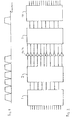
- FIG. 2 shows a known switching means for accomplishing this.
- the switching means includes a first set of switches 1.
- the first set of switches might have 16 inputs on the left hand side and 8 outputs on the right hand side.
- the inputs are the de-multiplexed channel slots and the outputs are the active r.f. signal paths out of those possible frequency slots.
- These switches are known as channel selection switches.
- the outputs are connected to the input of a second set of switches 2 which connect the, say, 8 inputs to a larger number, say, 11 individual amplifying channels.
- These switches are known as redundancy selection switches.
- Each individual channel may contain a travelling wave tube amplifier (TWTA).
- TWTA travelling wave tube amplifier
- a number, say three, of these channels are designated as redundant, in order to provide a backup in case any of the amplifiers designed to be operational fails during the lifetime of the satellite.
- the amplified signals pass through a set of switches 3 corresponding to the second set so that the active r.f. channels appear at the output of the set of switches 3 whatever amplifiers have been selected to be redundant, and these active r.f channels are returned to their appropriate signal slots in another set of switches 4 corresponding to the first set.
- the active outputs from the fourth set of switches are fed to filters and multiplexers for downward transmission.
- the inputs to the first set of switches 1 are conceptually arranged in pairs so that each output can be connected to one of two particular inputs.
- the procedure is reversed at the set of switches 4.
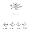
- the second set of switches 2 and their counterpart 3, for redundancy purposes, is more flexible and may consist of a ring of four port switches ( Figures 4a-4e).
- Each switch can connect a first port (a channel slot) to a second port (an r.f. signal path) (straight through - Figure 4b) or to a third or fourth port ( Figures 4c, 4e) connecting to respective positions of the neighbouring switches.
- the output can then be taken from the second port of the neighbouring switches to connect to those r.f. signal paths.
- the position of the non-operating or redundant amplifiers is selected before the satellite is launched (usually as a design feature), and the redundancy ring and spare amplifiers will only be used in the event of a failure.
- the switch ( Figure 4a) has an outer cylindrical body 12, and an inner rotor 11 containing waveguide sections 11a, 11b and 11c. The rotor is rotated appropriately to produce the arrangements of Figures 4b to 4e.
- the second set of switches could consist of eleven four port switches.
- the second port is connected to a respective TWTA.
- the third port of each switch is connected to the fourth port of the switch connected to the next above TWTA as seen in Figure 2, apart from the third port of the switch connected to the top TWTA as seen in Figure 2, which is connected by a link to the fourth port of the switch connected to the bottom TWTA as seen in Figure 2.
- the first ports of the eight switches connected to the TWTAs which have not been designated as redundant, are connected to the outputs of the switches 1.
- a TWTA fails when the satellite is in orbit, say, if the top TWTA (as seen in Figure 2) fails yet is connected to the output of the switch in the set 1 through which passes the top active c.f. signal path (as seen in Figure 2). Also, assume that the second TWTA from the top is designated as redundant ie. the switch in the set 2 it is connected to at the second port is not connected to an active r.f. signal path at the first port.
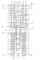
- switches 5 There are twenty-eight switches in a first row of switches 5 (the left-hand vertical now as seen in Figure 3), and each is a four port switch as illustrated in Figures 4a-e. The row is shown in two sections.
- the first port of each switch in the row 5 connects to a respective de-multiplexed channel slot, of which fourteen are active.
- the third and fourth ports of the switches are interconnected and two links L 1 , L 2 complete the ring.
- the second ports of the switches of the row 5 are connected to first ports of four port switches of a row 6.
- the row 6 is next to the row 5.
- the switches of the row 6 are also as illustrated in Figures 4a-4e.
- the third and fourth ports of the switches of the row 6 are also interconnected. In this case, the switches are contained in two rings, not one as for the switches 5, links L 3 and L 4 completing the ring.
- Twenty amplifiers each consisting of a driver limiter amplifier 9 and a travelling wave tube amplifier 10 are distributed between the twenty-eight switches, being connected to the second ports. Of those twenty amplifiers, six are designated as being redundant.
- the second ports of the other eight switches of the set 6 are connected to each other by means of links L 5 , L 6 , L 7 and L 8 (These links have counterparts L 15 -L 18 on the output side, and links L 1 -L 4 have counterparts L 14 -L 18 on the output side).
- the set of four ports switches 7 corresponds to the set 6, and connects the live r.f amplifiers 9, 10 to the set of four port switches 8, corresponding to the set 5, whereupon the now amplified r.f. signals are returned to the appropriate of the twenty-eight channel slots by the switches 8.
- the active outputs are fed to filters and multiplexers for downward transmission.
- the key to the invention is the use of four port switches for the rows 5 and 8 as well as for the rows 6 and 7.
- the signal can be redirected to frequency slot 5 using the third/fourth port interconnection of switches 5 5 , 5 6 , 5 7 or 6 5 , 6 6 , 6 7 or a combination of these. This would be feasible when slot 6 was not being used.
- Switches 7 and 8 are set corresponding to the settings of switches 6 and 5 respectively.
- the third slot down would be able to access amplifiers 9 and 10 via the interconnection of switches 6 17 and 6 16 or 16 17 and 16 18 , or 5 17 and 5 16 or 5 17 and 5 18 (using link L 5 ).
- channel slots so that pairs with amplifiers are interspersed with links to other outputs is particularly advantageous for maximum flexibility.
- a particular advantage of the switching means of the invention is for co-located satellites which might each cover a section of a broadband spectral region, so that if a channel failed on any of those satellites, the satellite of the invention would be able to be switched in to replace whatever the failed frequency was almost instantaneously.
- switches 5 may be arranged in two rings, like the switches 6, 7, or the latter may be arranged in a single ring.
- the links L 1 , L 2 may be omitted altogether, as could be the links L 5 , L 6 , L 7 , L 8 , and similarly on the output side.
- switches are four port switches, some of the switches may be two port switches (either allowing straight through communication or preventing straight through communication), or some may be three port (adjacent pairs of switches 5 or 6 may be interconnected but not connected to the switches on either side of the pair, with the corresponding changes on the output side.)
- the bodies of the switches forming the stator may be one unitary piece of material. As shown in Figure 3, there would be two such blocks on the input to the amplifiers, and a further two on the output. If desired, a single block could be used for the switches 5, 6 on the input and another single block for the switches 7, 8 on the output.
- the port interconnections may be formed in the block, but separate waveguide sections may be used instead.
- switches have all been shown as being as in Figure 4a ie. waveguide switches, some or all of them could be co-axial switches, especially on the input side. In such a case, contact would be made in a similar way with a rotor and stator arrangement but with no waveguide sections.
- the twenty-eight demultiplexer narrow band channels on the space craft may be fed by co-axial cable.
- Each co-axial line may be connected to a co-axial to waveguide transition (in the case when the input switches are waveguide switches).
- the frequency slots may be in the Ku band (10-18GHz), but the invention could also be used for other frequencies.
- the frequency of the signal may be the same in the input and output switches, down-conversion for the downlink taking place after the output switches, but this could be done in the amplification chain if desired.
Landscapes
- Engineering & Computer Science (AREA)
- Computer Networks & Wireless Communication (AREA)
- Signal Processing (AREA)
- Radio Relay Systems (AREA)
Applications Claiming Priority (2)
| Application Number | Priority Date | Filing Date | Title |
|---|---|---|---|
| GB9613628A GB2314725B (en) | 1996-06-28 | 1996-06-28 | Switching means for use on-board a spacecraft |
| GB9613628 | 1996-06-28 |
Publications (1)
| Publication Number | Publication Date |
|---|---|
| EP0817402A2 true EP0817402A2 (de) | 1998-01-07 |
Family
ID=10796065
Family Applications (1)
| Application Number | Title | Priority Date | Filing Date |
|---|---|---|---|
| EP97304382A Withdrawn EP0817402A2 (de) | 1996-06-28 | 1997-06-23 | Schaltmittel zum Gebrauch an Bord eines Raumfahrzeugs |
Country Status (4)
| Country | Link |
|---|---|
| US (1) | US6020796A (de) |
| EP (1) | EP0817402A2 (de) |
| CA (1) | CA2207699A1 (de) |
| GB (1) | GB2314725B (de) |
Cited By (2)
| Publication number | Priority date | Publication date | Assignee | Title |
|---|---|---|---|---|
| EP0951149A3 (de) * | 1998-04-18 | 2001-10-04 | Space Systems / Loral, Inc. | Konfigurierbares Nachrichtenübertragungsgerät das den Gebrauch nicht verwendeter Multiplexerkanäle während eines hohen Verbrauchsmodus erlaubt |
| EP1237299A1 (de) * | 2001-03-01 | 2002-09-04 | Alcatel | Schaltungsanordnung für modulare Signalrechnervorrichtung eines Satelliten im Weltraum und Satellit mit so einer Anordnung |
Families Citing this family (6)
| Publication number | Priority date | Publication date | Assignee | Title |
|---|---|---|---|---|
| US7369810B2 (en) * | 2001-10-05 | 2008-05-06 | The Boeing Company | Satellite transponder architecture with integral redundancy and beam selection capabilities |
| US8400215B2 (en) * | 2008-03-27 | 2013-03-19 | Mitsubishi Electric Corporation | Power amplification device for satellite communication device |
| US8803631B2 (en) * | 2010-03-22 | 2014-08-12 | Blackberry Limited | Method and apparatus for adapting a variable impedance network |
| JP6049047B2 (ja) * | 2011-09-30 | 2016-12-21 | Necスペーステクノロジー株式会社 | 冗長化増幅器及びその切替方法 |
| CN108352891A (zh) * | 2015-11-17 | 2018-07-31 | 威尔逊电子有限责任公司 | 具有多个信号链的蜂窝信号增强器 |
| CN108683446B (zh) * | 2018-03-29 | 2021-04-13 | 西安空间无线电技术研究所 | 一种通信卫星转发器双频带功放备份环及切换方法 |
Family Cites Families (7)
| Publication number | Priority date | Publication date | Assignee | Title |
|---|---|---|---|---|
| NL15881C (de) * | 1923-03-14 | |||
| JPS494771B1 (de) * | 1968-05-14 | 1974-02-02 | ||
| US4070637A (en) * | 1976-03-25 | 1978-01-24 | Communications Satellite Corporation | Redundant microwave configuration |
| US4198611A (en) * | 1977-08-01 | 1980-04-15 | Rca Corporation | Redundancy system with eight devices for five channels |
| JPS58172030A (ja) * | 1982-04-01 | 1983-10-08 | General Res Obu Erekutoronitsukusu:Kk | 広帯域信号の分配装置 |
| JPS61148926A (ja) * | 1984-12-24 | 1986-07-07 | Kokusai Denshin Denwa Co Ltd <Kdd> | 通信衛星中継器 |
| GB8819501D0 (en) * | 1988-08-17 | 1988-09-21 | British Aerospace | Spacecraft payload |
-
1996
- 1996-06-28 GB GB9613628A patent/GB2314725B/en not_active Expired - Fee Related
-
1997
- 1997-06-12 CA CA002207699A patent/CA2207699A1/en not_active Abandoned
- 1997-06-23 EP EP97304382A patent/EP0817402A2/de not_active Withdrawn
- 1997-06-24 US US08/881,332 patent/US6020796A/en not_active Expired - Fee Related
Cited By (3)
| Publication number | Priority date | Publication date | Assignee | Title |
|---|---|---|---|---|
| EP0951149A3 (de) * | 1998-04-18 | 2001-10-04 | Space Systems / Loral, Inc. | Konfigurierbares Nachrichtenübertragungsgerät das den Gebrauch nicht verwendeter Multiplexerkanäle während eines hohen Verbrauchsmodus erlaubt |
| EP1237299A1 (de) * | 2001-03-01 | 2002-09-04 | Alcatel | Schaltungsanordnung für modulare Signalrechnervorrichtung eines Satelliten im Weltraum und Satellit mit so einer Anordnung |
| FR2821700A1 (fr) * | 2001-03-01 | 2002-09-06 | Cit Alcatel | Agencement de connexion pour ensemble modulaire de traitement de signaux d'un satellite spatial et satellite equipe d'un tel agencement |
Also Published As
| Publication number | Publication date |
|---|---|
| GB2314725B (en) | 2000-03-08 |
| CA2207699A1 (en) | 1997-12-28 |
| GB9613628D0 (en) | 1996-08-28 |
| US6020796A (en) | 2000-02-01 |
| GB2314725A (en) | 1998-01-07 |
Similar Documents
| Publication | Publication Date | Title |
|---|---|---|
| US6278536B1 (en) | Optical transmission device for bi-directional optical communication | |
| EP0277188B1 (de) | Satellitenübertragungssystem mit durch gemeinsamen sender gespeisten vielfach-abwärtsrichtstrahlenbündeln | |
| CA2157209C (en) | Repeaters for multibeam satellites | |
| EP1076426B1 (de) | Dynamische Verstärker Konfiguration für Satelliten Systemen mit mehrfach Verbindungen und mit starkem Unterkanal Verbindungsvermögen | |
| US6020796A (en) | Switching means for use on-board a spacecraft | |
| US8248977B2 (en) | Routing of downlink channels in a communications satellite | |
| EP0278982B1 (de) | Filterkopplungsmatrix | |
| US7437075B2 (en) | Integrated reconfigurable optical add/drop multiplexer | |
| US20130100971A1 (en) | Output multiplexer | |
| US5033108A (en) | Signal repeater using shared amplification with selectable input/output connections | |
| US20020191899A1 (en) | Optical connection arrangements | |
| US8149869B2 (en) | Telecommunication network | |
| US4905239A (en) | R. F. signal distribution | |
| US6301225B1 (en) | Configurable communication apparatus that permits use of unused multiplexer channels when operating in high power mode | |
| US20030134595A1 (en) | Optimization of eirp via efficient redundancy pooling concepts | |
| US7256735B2 (en) | Satellite amplifier system | |
| US7199921B2 (en) | Two stage optical amplifier | |
| EP1328074A2 (de) | Schaltungsmechanismus für Abwärtsverbindungen in einem Satellit | |
| GB2202995A (en) | R F signal distribution | |
| EP0760561B1 (de) | Satelliten-Zwischenverstärker zur Funkkeulen-Umschaltung von Kanälen und Teilkanälen | |
| EP1249956A2 (de) | Verstärkerstruktur für in-Reihe Knoten | |
| CN101669302B (zh) | 通信卫星中下行链路信道的路由 | |
| JPH02296422A (ja) | 衛星搭載用中継装置 |
Legal Events
| Date | Code | Title | Description |
|---|---|---|---|
| PUAI | Public reference made under article 153(3) epc to a published international application that has entered the european phase |
Free format text: ORIGINAL CODE: 0009012 |
|
| AK | Designated contracting states |
Kind code of ref document: A2 Designated state(s): AT BE CH DE DK ES FI FR GB GR IE IT LI LU MC NL PT SE |
|
| AX | Request for extension of the european patent |
Free format text: AL;LT;LV;RO;SI |
|
| STAA | Information on the status of an ep patent application or granted ep patent |
Free format text: STATUS: THE APPLICATION IS DEEMED TO BE WITHDRAWN |
|
| 18D | Application deemed to be withdrawn |
Effective date: 20021231 |