EP1237299A1 - Schaltungsanordnung für modulare Signalrechnervorrichtung eines Satelliten im Weltraum und Satellit mit so einer Anordnung - Google Patents
Schaltungsanordnung für modulare Signalrechnervorrichtung eines Satelliten im Weltraum und Satellit mit so einer Anordnung Download PDFInfo
- Publication number
- EP1237299A1 EP1237299A1 EP02290146A EP02290146A EP1237299A1 EP 1237299 A1 EP1237299 A1 EP 1237299A1 EP 02290146 A EP02290146 A EP 02290146A EP 02290146 A EP02290146 A EP 02290146A EP 1237299 A1 EP1237299 A1 EP 1237299A1
- Authority
- EP
- European Patent Office
- Prior art keywords
- modules
- input
- nominal
- output
- redundant
- Prior art date
- Legal status (The legal status is an assumption and is not a legal conclusion. Google has not performed a legal analysis and makes no representation as to the accuracy of the status listed.)
- Granted
Links
- 239000011159 matrix material Substances 0.000 claims abstract description 60
- 238000006467 substitution reaction Methods 0.000 claims abstract description 7
- 238000004891 communication Methods 0.000 claims description 12
- 238000000429 assembly Methods 0.000 abstract 1
- 235000021183 entrée Nutrition 0.000 description 9
- 230000003321 amplification Effects 0.000 description 5
- 238000000034 method Methods 0.000 description 5
- 238000003199 nucleic acid amplification method Methods 0.000 description 5
- 230000008901 benefit Effects 0.000 description 3
- 230000008878 coupling Effects 0.000 description 3
- 238000010168 coupling process Methods 0.000 description 3
- 238000005859 coupling reaction Methods 0.000 description 3
- 230000008569 process Effects 0.000 description 3
- 238000010586 diagram Methods 0.000 description 2
- 230000008054 signal transmission Effects 0.000 description 2
- 239000007787 solid Substances 0.000 description 2
- 230000009471 action Effects 0.000 description 1
- 230000005540 biological transmission Effects 0.000 description 1
- 230000008859 change Effects 0.000 description 1
- 230000002950 deficient Effects 0.000 description 1
- 230000006866 deterioration Effects 0.000 description 1
- 239000004744 fabric Substances 0.000 description 1
- 239000000463 material Substances 0.000 description 1
- 230000000750 progressive effect Effects 0.000 description 1
- 230000009467 reduction Effects 0.000 description 1
Images
Classifications
-
- H—ELECTRICITY
- H04—ELECTRIC COMMUNICATION TECHNIQUE
- H04B—TRANSMISSION
- H04B7/00—Radio transmission systems, i.e. using radiation field
- H04B7/14—Relay systems
- H04B7/15—Active relay systems
- H04B7/185—Space-based or airborne stations; Stations for satellite systems
- H04B7/1851—Systems using a satellite or space-based relay
- H04B7/18515—Transmission equipment in satellites or space-based relays
Definitions
- the invention relates to a connection arrangement for an assembly. modular signal processing system on board a space satellite and particular of a telecommunications satellite.
- This connection arrangement is intended to be associated with a set consisting of nominal processing modules which are associated with redundant processing modules. These last are designed to be individually substituted for nominal modules, on order.
- the invention also relates to a space satellite equipped with an assembly modular processing and provided with such a connection arrangement.
- a space satellite When a space satellite has a set organized in such a way modular to process received signals, it usually combines redundant processing to nominal processing modules. These modules redundant are intended to be individually substituted for one or other of the nominal modules normally responsible for processing, if a failure prevents correct operation of one of these nominal modules, while the satellite is in orbit.
- the substitution of a redundant module for a given nominal module involves the establishment of links allowing, on the one hand, to the signal transmitted from an input, for processing by said given nominal module, to be received by the redundant module substituted and, on the other hand, the signal, processed by said module redundant, to be referred at the output of this module, so as to replace the signal previously processed by the given nominal module.
- These connections are generally provided through a connection arrangement having an input subset through which the signals to be processed are received. This reception may be carried out through a specified number of inputs from which the received signals are selectively each referred to a different module for treatment.
- the connection arrangement also includes an output sub-assembly, for example through which the signals processed by the modules are routed in a way determined from these modules.
- the signals to be processed are, for example, signals radio frequencies, received by one or more antennas for receiving a satellite. They are selectively oriented towards processing modules, via a input sub-assembly as mentioned above, usually after a first amplification and, if necessary, a selection.
- the signals processed by the modules are for example referred to amplifiers, before operation on board the satellite or retransmission from this satellite, in particular in the case of a satellite of telecommunications.
- electromechanical switching means which do not consume no energy and are in a stable state from the time they are in one of the switched positions they are likely to take.
- a telecommunications satellite is equipped with a connection arrangement comprising a input sub-assembly and an output sub-assembly which are provided with means for switching made in the form of matrices.
- These matrices are arranged on the side and on the other side of a processing unit which is organized in a modular manner.
- a first matrix constitutes the input subset and makes it possible to connect individually each signal input to be processed at one of the modules in the set of processing, for low power signal transmissions.
- a second matrix constitutes the output subset and allows to link individually each of the modules in the processing set has a strong signal output power.
- These matrices are composed using switching devices electromechanical and are connected to connections made using cables coaxial or waveguides.
- these matrices consist of switching elements, or switches, which are stable in each of their switched positions and which have no risk of failure, once switched.
- the input sub-assembly of a connection arrangement includes a series of nominal point-to-point connections, each made between a signal input and a processing module via a electromechanical switching device.
- This body makes it possible to replace, on control, the nominal link that it creates between an input and a module by a emergency link between this input and one of the redundant processing modules.
- connection arrangement intended to be associated with a set of communication signal processing composed of nominal processing modules with which processing modules are associated redundant, which can be individually substituted for nominal modules on controls, on board an orbiting satellite, said connection arrangement including an input subset via which the signals to be processed, separately received at a determined number of layout entries, are selectively referred each to a module for treatment, as well as a subset output, through which the processed signals are routed by predetermined way from the modules that processed them
- said input sub-assembly includes passive couplers, called input couplers, associated with a matrix of switching, known as the first matrix, the passive couplers being respectively connected each, on the one hand, at one of the different entrances of the arrangement and comprising each a first output port connected to the input of one of the different modules nominal and a second output port connected to one of the different inputs individual ones comprised by said first switching matrix.
- the outputs of this matrix are each connected at the input of one of the different redundant modules and said matrix, made up of electronic switches, is kept inactive, until receipt of a command to replace a redundant module at one of the nominal modules, coming from a control unit supervising the layout. Therefore the matrix which comprises the input subset is without influence so much it is not activated and it is not likely to be the cause of a failure, throughout the time that the connection arrangement operates by exploiting only nominal modules, i.e. as long as it is in the normal running.
- the arrangement of connection includes an input subset including passive couplers asymmetrical that have a difference in power level for their two output ports. This difference in levels is intended to compensate for the loss of power affecting a signal which is transmitted between a passive coupler and a module redundant through the switching matrix, when this matrix is made active.
- the output sub-assembly includes passive couplers, called output couplers, associated with a switching matrix, called second matrix.
- These passive output couplers are respectively connected each to one of the different outputs of the arrangement and each have a first port input connected to the output of one of the different nominal modules and a second port input connected to one of the different individual outputs comprised by the second switching matrix, the inputs of which are each connected at the output of a different redundant modules.
- Said second matrix consisting of electronic switches, is kept inactive, until a substitution command of a redundant module to one of the nominal modules in from a control unit supervising the layout.
- the invention also relates to a space satellite equipped with a set of communication signal processing, composed of processing modules nominal and redundant processing modules that are individually substitutable for nominal modules on order, and an arrangement of connection comprising an input subset, through which the signals to be processed, separately received at a determined number of signal inputs the layout are selectively directed each to a different module for processing, and an output subset, through which the signals treated are referred in a determined manner from the modules which treated them.
- the satellite comprises a connection arrangement associated with a signal processing assembly, composed modules each responsible for amplifying the communication signal that he receives.
- the satellite comprises a connection arrangement associated with a signal processing assembly, composed modules each responsible for converting the signal to frequency communication he receives.
- the satellite includes a connection arrangement associated with a processing assembly signals, composed of modules each responsible for processing the signal communication he receives.
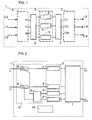
- Figure 1 shows a block diagram of a space satellite including a connection arrangement for providing input and connection links output necessary for the operation of a modular treatment unit satellite signals.
- FIG. 2 presents a diagram relating to an example of arrangement of connection, according to the invention, associated with a set of signal processing in a telecommunications satellite.
- connection arrangement presented in Figure 1 is intended to be installed in a space satellite 1, such as for example a telecommunications satellite, to provide the signal input and output links of a modular set of signal processing 2.
- This set is assumed to be composed of a plurality of nominal processing modules, here symbolized by two modules 3, to which are associated redundant processing modules, here symbolized by a 3 'module.
- the redundant modules of which the number is generally less, are provided for be able to be individually substituted for nominal modules, if necessary.
- Each nominal module is assumed to have means enabling it to process a communication signal and for example a radio frequency signal, as well as each redundant module.
- a module and in particular a redundant module can possibly have the means to deal with any of the signals belonging to a determined group of such signals.
- the signals to be processed by a modular processing unit 2 are assumed individually received via inputs, here referenced from I1 to IN, while the processed signals are assumed to be supplied to outputs, here referenced by O1 to OM, the numbers M and N possibly being identical.
- the signals to be processed, supplied by the inputs I1 to IN may for example be signals which have been received via a reception antenna, not shown, which are obtained via a hardware link L1 and via an input interface 4 then having a function of demultiplexer.
- These signals to be processed can alternatively be signals which have been received via different receiving antennas and transmitted at the inputs, via links such as L2 and L'2, via an interface input 4 differing at least partially from that mentioned above, by example an input interface ensuring pre-amplification of the signals received by the satellite.
- the signals processed, supplied at outputs O1 to ON are likely to be multiplexed at an interface of output 5 to be able to be transmitted by a L3 link to a retransmission antenna of the satellite or for the purpose of operation by equipment in the satellite itself. They can alternatively be transmitted via separate links, here symbolized by the links L4 and L4 ', and via an output interface 5 different from the previous one, either to different retransmitting antennas, or to equipment different from the satellite.
- the number of processing modules 3, 3 ′ comprised by the set of treatment 2 differs in principle from that of the expected number of inputs I1 to In, in the since a number of nominal modules is provided equal to the number N of input and a determined number of additional redundant modules. It is the same with regard to the respective numbers of output O1 to ON and of modules nominal and redundant. Therefore, it is necessary to have an arrangement of connection equipped with an input sub-assembly 6 for routing the signals to process received separately at each of the inputs I1 to IN to a module 3 or 3 'for processing, as well as an output sub-assembly 7 via from which the processed signals are routed in a predetermined manner from the 3 or 3 'modules that processed them.
- the processing carried out by the modules on the signals they receive can be carried out at different purposes and in particular for signal amplification purposes and / or frequency change, as already indicated above.
- processing modules 3, 3 ′ of the assembly 2 are likely to contain active components, they present the risk of being affected by faults caused by failures concerning these components. This leads to implementing a connection arrangement input assembly modular to replace a redundant module in the event of a fault nominal module with which it is compatible. If N is the number of distinct signals provided at the level of the processing unit of a satellite, there is therefore provided a number N of nominal modules 3, initially in service, and of P modules 3 'redundant, each capable of replacing a faulty nominal module.
- connection arrangement having an input subassembly 6 for connecting each input I1 to IN of signals to a passive coupler 8 which is individually its assigned and which therefore receives the signal transmitted by this input.
- Each passive coupler 8 has two outputs, here called output ports. A first of the ports of each passive coupler is individually connected to a nominal module 3 to which it transmits the signals received by the coupler.
- the second of the two output ports of each coupler 8 is susceptible to be connected to a 3 'redundant module via a matrix of switching 9 at the inputs of which all couplers 8 are individually connected by their respective second output ports.
- This matrix is composed using active components, constituting electronic switches, and for example in the form of an MMIC matrix (for "microwave monolithic integrated circuit"). Its purpose is to allow the transmission of the signals received by a coupler 8, for processing by a nominal module 3, to a redundant module 3 'capable of to replace this nominal module 3, when it fails.
- the 3 'redundant modules are each connected to an output corresponding to them individually assigned, at the switching matrix 9.
- the passive couplers 8 are capable of being produced in MMIC technique as well as the active matrix 9.
- the modules 3 and 3 ' are for example amplification modules with tubes with progressive waves, designated by the acronym TOP, or amplifiers of solid state power, designated by the acronym SSPA, (for "solid state power amplify").
- Each processing module whether nominal or redundant, has an output designed to be connected to an individual input of the output sub-assembly 7.
- the latter is here assumed to be carried out, in a known manner, in the form of a matrix incorporated using electromechanical switching components consuming no energy from the time they were switched to one or the other from their stable positions.
- This matrix makes it possible to route each of the signals processed from the module that processed it to one of the signal outputs, such as O1 and ON, that this matrix serves and this whatever the nominal or redundant module which has it treaty.
- the matrix constituting the output sub-assembly 7 is for example a power matrix, produced in a manner known to those skilled in the art, using electromechanical switching components, which are therefore not detailed here.
- the interposition of the switching matrix 9, between the couplers 8 and the 3 'redundant modules introduces a decrease in signal power level which are brought to cross it, it being understood that such a matrix is ordinarily composed of a plurality of stages, at least some of which are dissipative, when is carried out in electronic form. So there is a need to take action avoiding the substitution of a 3 'redundant module for a module nominal 3 faulty, does not result in a lowering of the power level of the processed signals which are provided by the redundant module compared to those which would have supplied the nominal module, if it had not failed.
- the couplers are made asymmetrically so as to present a difference in power levels at level of their two output ports. This difference is used to compensate for advance the loss of power, caused by the switching matrix 9, which affects the signals that this matrix 9 transmits to the redundant modules.
- the transmission of signals between one of the inputs, such as I1 or IN, and a outputs, such as O1 or ON, are provided through a nominal channel including a passive coupler 8 and a nominal module 3, as long as it is not planned to replace a redundant module to the nominal module, to compensate for a failure noted at level of said nominal channel.
- the switching matrix 9 can be maintained in an inactive state, for which it does not consume energy, as long as no control signal has been transmitted from the control unit 10 to command a switching allowing the substitution of a redundant module for a nominal module. This state of inactivity is maintained until it is detected, either at the satellite level or at the ground station level, signal deterioration indicating operation defective for one of the nominal routes used, as part of the processing performed by the nominal modules of processing set 2. Like the switch fabric 9 is out of nominal paths, it is not likely disturb the nominal operation and can be kept off, without disadvantage.
- the output sub-assembly of a satellite spatial can also include passive couplers associated with a matrix of switching, known as the second matrix, which is distinct from that provided for in the subset input.
- passive couplers called output couplers to differentiate them from above, are each connected to one of the different outputs of the arrangement. They each have a first input port connected to the output of a different nominal modules and a second input port connected to one of the different individual outputs comprised by the second switching matrix whose inputs are each connected at the output of one of the different modules redundant.
- the second matrix consists of electronic switches and it is kept inactive until receipt of a command to replace a redundant module to one of the nominal modules coming from a control supervising the layout.
- connection arrangement comprising an input sub-assembly and a sub-assembly output arranged on either side of the modules of a set of processing, as envisaged here, and of which only the output subset comprises passive couplers and a switching matrix composed of switches electronic arrangements, as indicated in the variant mentioned above.
Landscapes
- Engineering & Computer Science (AREA)
- Physics & Mathematics (AREA)
- Astronomy & Astrophysics (AREA)
- Aviation & Aerospace Engineering (AREA)
- General Physics & Mathematics (AREA)
- Computer Networks & Wireless Communication (AREA)
- Signal Processing (AREA)
- Radio Relay Systems (AREA)
- Input Circuits Of Receivers And Coupling Of Receivers And Audio Equipment (AREA)
- Variable-Direction Aerials And Aerial Arrays (AREA)
- Two-Way Televisions, Distribution Of Moving Picture Or The Like (AREA)
- Details Of Television Systems (AREA)
Applications Claiming Priority (2)
| Application Number | Priority Date | Filing Date | Title |
|---|---|---|---|
| FR0102809A FR2821700B1 (fr) | 2001-03-01 | 2001-03-01 | Agencement de connexion pour ensemble modulaire de traitement de signaux d'un satellite spatial et satellite equipe d'un tel agencement |
| FR0102809 | 2001-03-01 |
Publications (2)
| Publication Number | Publication Date |
|---|---|
| EP1237299A1 true EP1237299A1 (de) | 2002-09-04 |
| EP1237299B1 EP1237299B1 (de) | 2004-12-01 |
Family
ID=8860618
Family Applications (1)
| Application Number | Title | Priority Date | Filing Date |
|---|---|---|---|
| EP02290146A Expired - Lifetime EP1237299B1 (de) | 2001-03-01 | 2002-01-21 | Schaltungsanordnung für modulare Signalrechnervorrichtung eines Satelliten im Weltraum und Satellit mit so einer Anordnung |
Country Status (4)
| Country | Link |
|---|---|
| EP (1) | EP1237299B1 (de) |
| AT (1) | ATE284097T1 (de) |
| DE (1) | DE60202087D1 (de) |
| FR (1) | FR2821700B1 (de) |
Citations (4)
| Publication number | Priority date | Publication date | Assignee | Title |
|---|---|---|---|---|
| US4316159A (en) * | 1979-01-22 | 1982-02-16 | Rca Corporation | Redundant microwave switching matrix |
| EP0752756A2 (de) * | 1995-07-07 | 1997-01-08 | Fujitsu Compound Semiconductor, Inc. | Gegentakt-Frequenzumsetzer für Satellitenübertragungen und signalkombinierender hybrider Ring |
| US5696470A (en) * | 1995-06-07 | 1997-12-09 | Comsat Corporation | Solid-state electronic switching module |
| EP0817402A2 (de) * | 1996-06-28 | 1998-01-07 | Matra Marconi Space Uk Limited | Schaltmittel zum Gebrauch an Bord eines Raumfahrzeugs |
-
2001
- 2001-03-01 FR FR0102809A patent/FR2821700B1/fr not_active Expired - Fee Related
-
2002
- 2002-01-21 EP EP02290146A patent/EP1237299B1/de not_active Expired - Lifetime
- 2002-01-21 AT AT02290146T patent/ATE284097T1/de not_active IP Right Cessation
- 2002-01-21 DE DE60202087T patent/DE60202087D1/de not_active Expired - Lifetime
Patent Citations (4)
| Publication number | Priority date | Publication date | Assignee | Title |
|---|---|---|---|---|
| US4316159A (en) * | 1979-01-22 | 1982-02-16 | Rca Corporation | Redundant microwave switching matrix |
| US5696470A (en) * | 1995-06-07 | 1997-12-09 | Comsat Corporation | Solid-state electronic switching module |
| EP0752756A2 (de) * | 1995-07-07 | 1997-01-08 | Fujitsu Compound Semiconductor, Inc. | Gegentakt-Frequenzumsetzer für Satellitenübertragungen und signalkombinierender hybrider Ring |
| EP0817402A2 (de) * | 1996-06-28 | 1998-01-07 | Matra Marconi Space Uk Limited | Schaltmittel zum Gebrauch an Bord eines Raumfahrzeugs |
Also Published As
| Publication number | Publication date |
|---|---|
| DE60202087D1 (de) | 2005-01-05 |
| ATE284097T1 (de) | 2004-12-15 |
| FR2821700B1 (fr) | 2003-05-23 |
| EP1237299B1 (de) | 2004-12-01 |
| FR2821700A1 (fr) | 2002-09-06 |
Similar Documents
| Publication | Publication Date | Title |
|---|---|---|
| US6331906B1 (en) | Method and apparatus for operation, protection and restoration of heterogeneous optical communication networks | |
| US5986783A (en) | Method and apparatus for operation, protection, and restoration of heterogeneous optical communication networks | |
| US7085496B2 (en) | Passive add/drop amplifier for optical networks and method | |
| US7184663B2 (en) | Optical ring network with hub node and method | |
| CN100420173C (zh) | 光通信系统 | |
| EP0505284B1 (de) | Satellitentelekommunikationseinrichtung, die für mehrere Ausleuchtzonen verwendungsfähig ist | |
| US20050031345A1 (en) | Method and apparatus for operation, protection, and restoration of heterogeneous optical communication networks | |
| US7283740B2 (en) | Optical ring network with optical subnets and method | |
| EP1508216A2 (de) | Optisches ringnetzwerk mit knoten und verfahren | |
| EP1170823B1 (de) | Telekommunikationsantenne mit grossem Erdabdekkungsbereich | |
| EP2104243B1 (de) | Funknetz | |
| EP3991309B1 (de) | Verfahren und vorrichtung für einen optischen sender-empfänger | |
| EP0812077B1 (de) | Endgerät für eine gesicherte bidirektionale, nach der synchronen digitalen Hierarchie multiplexierte Daten übermittelnde Verbindung | |
| EP1351416B1 (de) | System und Verfahren zur Verstärkung von Signalen in einem optischen Netzwerk | |
| EP1237299B1 (de) | Schaltungsanordnung für modulare Signalrechnervorrichtung eines Satelliten im Weltraum und Satellit mit so einer Anordnung | |
| US20040008404A1 (en) | Distributed raman amplifier for optical network and method | |
| EP1499013B1 (de) | Satelliten-Verstärkervorrichtung | |
| US7283739B2 (en) | Multiple subnets in an optical ring network and method | |
| US7199921B2 (en) | Two stage optical amplifier | |
| EP3794747A1 (de) | Verfahren zur verwaltung des telekommunikationsdatenverkehrs eines satellitenkommunikationssystems mit sehr hohem durchsatz | |
| US6822972B1 (en) | Bidirectional communication system with ring configuration | |
| EP1545035B1 (de) | Raum- und Frequenz-Crossconnect für einen Satelliten-Kommunikation-Verstärker und zugehöriger Verstärker und Satellit | |
| EP1104124B1 (de) | Leitweglenkung in einem Satelliten Kommunikationssystem | |
| EP1317162B1 (de) | Rückgrat Schnittstelle für Raumfahrzeug und Kommunikationsnetz mit einer solchen Schnittstelle | |
| JP4485355B2 (ja) | 光信号を分配するシステム及び方法 |
Legal Events
| Date | Code | Title | Description |
|---|---|---|---|
| PUAI | Public reference made under article 153(3) epc to a published international application that has entered the european phase |
Free format text: ORIGINAL CODE: 0009012 |
|
| AK | Designated contracting states |
Kind code of ref document: A1 Designated state(s): AT BE CH CY DE DK ES FI FR GB GR IE IT LI LU MC NL PT SE TR |
|
| AX | Request for extension of the european patent |
Free format text: AL;LT;LV;MK;RO;SI |
|
| 17P | Request for examination filed |
Effective date: 20030304 |
|
| AKX | Designation fees paid |
Designated state(s): AT BE CH CY DE DK ES FI FR GB GR IE IT LI LU MC NL PT SE TR |
|
| GRAP | Despatch of communication of intention to grant a patent |
Free format text: ORIGINAL CODE: EPIDOSNIGR1 |
|
| GRAS | Grant fee paid |
Free format text: ORIGINAL CODE: EPIDOSNIGR3 |
|
| GRAA | (expected) grant |
Free format text: ORIGINAL CODE: 0009210 |
|
| AK | Designated contracting states |
Kind code of ref document: B1 Designated state(s): AT BE CH CY DE DK ES FI FR GB GR IE IT LI LU MC NL PT SE TR |
|
| PG25 | Lapsed in a contracting state [announced via postgrant information from national office to epo] |
Ref country code: GB Free format text: LAPSE BECAUSE OF FAILURE TO SUBMIT A TRANSLATION OF THE DESCRIPTION OR TO PAY THE FEE WITHIN THE PRESCRIBED TIME-LIMIT Effective date: 20041201 Ref country code: IT Free format text: LAPSE BECAUSE OF FAILURE TO SUBMIT A TRANSLATION OF THE DESCRIPTION OR TO PAY THE FEE WITHIN THE PRESCRIBED TIME-LIMIT;WARNING: LAPSES OF ITALIAN PATENTS WITH EFFECTIVE DATE BEFORE 2007 MAY HAVE OCCURRED AT ANY TIME BEFORE 2007. THE CORRECT EFFECTIVE DATE MAY BE DIFFERENT FROM THE ONE RECORDED. Effective date: 20041201 Ref country code: TR Free format text: LAPSE BECAUSE OF FAILURE TO SUBMIT A TRANSLATION OF THE DESCRIPTION OR TO PAY THE FEE WITHIN THE PRESCRIBED TIME-LIMIT Effective date: 20041201 Ref country code: IE Free format text: LAPSE BECAUSE OF FAILURE TO SUBMIT A TRANSLATION OF THE DESCRIPTION OR TO PAY THE FEE WITHIN THE PRESCRIBED TIME-LIMIT Effective date: 20041201 Ref country code: FI Free format text: LAPSE BECAUSE OF FAILURE TO SUBMIT A TRANSLATION OF THE DESCRIPTION OR TO PAY THE FEE WITHIN THE PRESCRIBED TIME-LIMIT Effective date: 20041201 Ref country code: NL Free format text: LAPSE BECAUSE OF FAILURE TO SUBMIT A TRANSLATION OF THE DESCRIPTION OR TO PAY THE FEE WITHIN THE PRESCRIBED TIME-LIMIT Effective date: 20041201 Ref country code: AT Free format text: LAPSE BECAUSE OF FAILURE TO SUBMIT A TRANSLATION OF THE DESCRIPTION OR TO PAY THE FEE WITHIN THE PRESCRIBED TIME-LIMIT Effective date: 20041201 |
|
| REG | Reference to a national code |
Ref country code: GB Ref legal event code: FG4D Free format text: NOT ENGLISH |
|
| REG | Reference to a national code |
Ref country code: CH Ref legal event code: EP |
|
| REG | Reference to a national code |
Ref country code: IE Ref legal event code: FG4D Free format text: FRENCH |
|
| REF | Corresponds to: |
Ref document number: 60202087 Country of ref document: DE Date of ref document: 20050105 Kind code of ref document: P |
|
| PG25 | Lapsed in a contracting state [announced via postgrant information from national office to epo] |
Ref country code: LU Free format text: LAPSE BECAUSE OF NON-PAYMENT OF DUE FEES Effective date: 20050121 Ref country code: CY Free format text: LAPSE BECAUSE OF FAILURE TO SUBMIT A TRANSLATION OF THE DESCRIPTION OR TO PAY THE FEE WITHIN THE PRESCRIBED TIME-LIMIT Effective date: 20050121 |
|
| PG25 | Lapsed in a contracting state [announced via postgrant information from national office to epo] |
Ref country code: MC Free format text: LAPSE BECAUSE OF NON-PAYMENT OF DUE FEES Effective date: 20050131 Ref country code: BE Free format text: LAPSE BECAUSE OF NON-PAYMENT OF DUE FEES Effective date: 20050131 |
|
| PG25 | Lapsed in a contracting state [announced via postgrant information from national office to epo] |
Ref country code: SE Free format text: LAPSE BECAUSE OF FAILURE TO SUBMIT A TRANSLATION OF THE DESCRIPTION OR TO PAY THE FEE WITHIN THE PRESCRIBED TIME-LIMIT Effective date: 20050301 Ref country code: DK Free format text: LAPSE BECAUSE OF FAILURE TO SUBMIT A TRANSLATION OF THE DESCRIPTION OR TO PAY THE FEE WITHIN THE PRESCRIBED TIME-LIMIT Effective date: 20050301 Ref country code: GR Free format text: LAPSE BECAUSE OF FAILURE TO SUBMIT A TRANSLATION OF THE DESCRIPTION OR TO PAY THE FEE WITHIN THE PRESCRIBED TIME-LIMIT Effective date: 20050301 |
|
| PG25 | Lapsed in a contracting state [announced via postgrant information from national office to epo] |
Ref country code: DE Free format text: LAPSE BECAUSE OF FAILURE TO SUBMIT A TRANSLATION OF THE DESCRIPTION OR TO PAY THE FEE WITHIN THE PRESCRIBED TIME-LIMIT Effective date: 20050302 |
|
| PG25 | Lapsed in a contracting state [announced via postgrant information from national office to epo] |
Ref country code: ES Free format text: LAPSE BECAUSE OF FAILURE TO SUBMIT A TRANSLATION OF THE DESCRIPTION OR TO PAY THE FEE WITHIN THE PRESCRIBED TIME-LIMIT Effective date: 20050312 |
|
| NLV1 | Nl: lapsed or annulled due to failure to fulfill the requirements of art. 29p and 29m of the patents act | ||
| GBV | Gb: ep patent (uk) treated as always having been void in accordance with gb section 77(7)/1977 [no translation filed] |
Effective date: 20041201 |
|
| REG | Reference to a national code |
Ref country code: IE Ref legal event code: FD4D |
|
| BERE | Be: lapsed |
Owner name: ALCATEL Effective date: 20050131 |
|
| PLBE | No opposition filed within time limit |
Free format text: ORIGINAL CODE: 0009261 |
|
| STAA | Information on the status of an ep patent application or granted ep patent |
Free format text: STATUS: NO OPPOSITION FILED WITHIN TIME LIMIT |
|
| 26N | No opposition filed |
Effective date: 20050902 |
|
| PG25 | Lapsed in a contracting state [announced via postgrant information from national office to epo] |
Ref country code: CH Free format text: LAPSE BECAUSE OF NON-PAYMENT OF DUE FEES Effective date: 20060131 Ref country code: LI Free format text: LAPSE BECAUSE OF NON-PAYMENT OF DUE FEES Effective date: 20060131 |
|
| REG | Reference to a national code |
Ref country code: CH Ref legal event code: PL |
|
| REG | Reference to a national code |
Ref country code: FR Ref legal event code: CD |
|
| BERE | Be: lapsed |
Owner name: *ALCATEL Effective date: 20050131 |
|
| PG25 | Lapsed in a contracting state [announced via postgrant information from national office to epo] |
Ref country code: PT Free format text: LAPSE BECAUSE OF NON-PAYMENT OF DUE FEES Effective date: 20050501 |
|
| REG | Reference to a national code |
Ref country code: FR Ref legal event code: PLFP Year of fee payment: 15 |
|
| PGFP | Annual fee paid to national office [announced via postgrant information from national office to epo] |
Ref country code: FR Payment date: 20151223 Year of fee payment: 15 |
|
| REG | Reference to a national code |
Ref country code: FR Ref legal event code: ST Effective date: 20170929 |
|
| PG25 | Lapsed in a contracting state [announced via postgrant information from national office to epo] |
Ref country code: FR Free format text: LAPSE BECAUSE OF NON-PAYMENT OF DUE FEES Effective date: 20170131 |