EP0816639B1 - Kühlgaskrümmer für Dichtungsspaltregelung einer Turbomaschine - Google Patents
Kühlgaskrümmer für Dichtungsspaltregelung einer Turbomaschine Download PDFInfo
- Publication number
- EP0816639B1 EP0816639B1 EP97401486A EP97401486A EP0816639B1 EP 0816639 B1 EP0816639 B1 EP 0816639B1 EP 97401486 A EP97401486 A EP 97401486A EP 97401486 A EP97401486 A EP 97401486A EP 0816639 B1 EP0816639 B1 EP 0816639B1
- Authority
- EP
- European Patent Office
- Prior art keywords
- gas
- blowing device
- partitions
- chambers
- orifices
- Prior art date
- Legal status (The legal status is an assumption and is not a legal conclusion. Google has not performed a legal analysis and makes no representation as to the accuracy of the status listed.)
- Expired - Lifetime
Links
- 239000000112 cooling gas Substances 0.000 title 1
- 238000005192 partition Methods 0.000 claims description 29
- 238000007664 blowing Methods 0.000 claims description 19
- 230000003247 decreasing effect Effects 0.000 claims description 3
- 230000004888 barrier function Effects 0.000 claims 5
- 239000007789 gas Substances 0.000 description 32
- 238000009423 ventilation Methods 0.000 description 4
- 239000002184 metal Substances 0.000 description 3
- 229910052751 metal Inorganic materials 0.000 description 3
- 238000001816 cooling Methods 0.000 description 2
- 210000003462 vein Anatomy 0.000 description 2
- 229910000746 Structural steel Inorganic materials 0.000 description 1
- 238000010276 construction Methods 0.000 description 1
- 238000005553 drilling Methods 0.000 description 1
- 230000002349 favourable effect Effects 0.000 description 1
- 239000012634 fragment Substances 0.000 description 1
- 238000004519 manufacturing process Methods 0.000 description 1
- 150000002739 metals Chemical class 0.000 description 1
- 238000013021 overheating Methods 0.000 description 1
- 238000005086 pumping Methods 0.000 description 1
- 230000000717 retained effect Effects 0.000 description 1
- 238000007789 sealing Methods 0.000 description 1
- 238000000926 separation method Methods 0.000 description 1
- 230000001052 transient effect Effects 0.000 description 1
- 238000011144 upstream manufacturing Methods 0.000 description 1
Images


Classifications
-
- F—MECHANICAL ENGINEERING; LIGHTING; HEATING; WEAPONS; BLASTING
- F01—MACHINES OR ENGINES IN GENERAL; ENGINE PLANTS IN GENERAL; STEAM ENGINES
- F01D—NON-POSITIVE DISPLACEMENT MACHINES OR ENGINES, e.g. STEAM TURBINES
- F01D11/00—Preventing or minimising internal leakage of working-fluid, e.g. between stages
- F01D11/08—Preventing or minimising internal leakage of working-fluid, e.g. between stages for sealing space between rotor blade tips and stator
- F01D11/14—Adjusting or regulating tip-clearance, i.e. distance between rotor-blade tips and stator casing
- F01D11/20—Actively adjusting tip-clearance
- F01D11/24—Actively adjusting tip-clearance by selectively cooling-heating stator or rotor components
-
- F—MECHANICAL ENGINEERING; LIGHTING; HEATING; WEAPONS; BLASTING
- F01—MACHINES OR ENGINES IN GENERAL; ENGINE PLANTS IN GENERAL; STEAM ENGINES
- F01D—NON-POSITIVE DISPLACEMENT MACHINES OR ENGINES, e.g. STEAM TURBINES
- F01D25/00—Component parts, details, or accessories, not provided for in, or of interest apart from, other groups
- F01D25/08—Cooling; Heating; Heat-insulation
- F01D25/14—Casings modified therefor
Definitions
- the subject of the invention is a device for gas blowing to adjust the clearance inside of a turbomachine.
- the clearance adjustment gases therefore do not open directly in the room delimited by the ring in leaving the routing lines, but pass first by a mixer.
- This mixer is composed of a plurality of rooms in succession, having straight sections analogous and substantially separated by partitions parallel, and the partitions are pierced with orifices always more numerous from one partition to another towards the stator ring. This produces a flow in gas tree from one room to another, so well that they arrive with a great homogeneity of flow and temperature in front of the ring.
- the orifices may consist of simple drillings operated through partitions of separation of the rooms or in short pipes. In both cases, there is only a pressure drop significantly lower than with devices ordinary pipelines, which generally involve significant disturbances in the flow by large variations in direction or speed.
- the numbers of orifices can be in geometric progression from one partition to another, by twice as many examples, and they're from preferably distributed in circumferential rows in identical number for all partitions, so that only the angular pitch varies from one partition to another.
- the rooms can be annular and separated by transverse partitions in the turbomachine and crown: they are then in shape stacked cylinders; or they can be substantially annular but separated by partitions cylindrical and concentric: they are then arranged in concentric cylinders.
- the orifices between chambers can be replaced by connecting ducts if the rooms are not contiguous.
- This design applies in peculiar to elongated devices where the chambers face different portions to be ventilated from the ring and are pierced with blowing holes towards these portions.
- the advantage of having conduits always more numerous between pairs of rooms successive towards the flow of gas from ventilation remains, but the appropriate realization of the invention can be implemented somewhat different from the achievements previously exposed. he it is no longer necessary that the rooms have the same cross section if the gas gradually leaks through the orifices which pierce them: on the contrary favorable that their cross sections decrease by one room to room to maintain speed and almost constant pressure. But it should always that the rooms have the same extent, that is to say the same angular extension in the case normal annular chambers or ring portion.
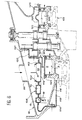
- the turbomachine portion shown on the different figures basically includes a fragment of stator 1 which comprises, facing two stages movable blades 2, two rings 3 formed of a skin metallic substantially cylindrical and which carries sealing segments 4, located just in front of the ends movable blades 2, via a ring of fixing 5.
- a chamber 6 or 106 is provided behind each of the rings 3, and two low walls 7, in one piece with ring 3, also delimit it on the sides in the realization of figure 1.
- the mixer 8 subject of the invention is of annular shape, closes the outside of one of the rooms 6 and is screwed by its ends longitudinal to two sheets 9 which form extensions of the walls 7.
- An outer casing ring 10 surrounds and covers the mixer 8. It is however crossed by four gas supply conduits 11 which end in a first chamber 12 of the mixer 8. These conduits 11 are arranged at an angle right around the machine, and only one is shown for that in figure 1.
- Gas flows enter more precisely through the external wall of the mixer 8 and have first a centripetal direction by leaving ducts 11, before straightening in the first chamber 12 to take an axial direction. They then enter a second chamber 14, then a third chamber 15, before leaving the mixer 8 and go to the first room 6 assigned to ring diameter adjustment 3.
- Each of these passages is carried out by ever more numerous orifices: while there were four conduits 11, there are eight orifices 16 between the first room 12 and second room 14, sixteen orifices 17 between the second chamber 14 and the third chamber 15 and thirty-two orifices 18 at the exit from third room 15, as seen well on figures 2 to 5 which represent half-circumferences of mixer 8, the rest being identical.
- the holes 16, 17, 18 are respectively arranged around the machine in a single row, so that their angular pitch is two each time times smaller. This results in a uniformization of the flow and some mixing of the gases which helps to equalize both the flow and the temperature, i.e. thermal expansion produced.
- the mixer 8 can be formed of two circular sheet metal plates, corresponding substantially to external 13 and internal 19 faces of the chambers 12, 14 and 15 annular and stamped to join at the longitudinal ends and at the partitions 16 and 17, except at the orifices; these sheets include borders end 24 by which they are screwed to sheets 9 integral with the walls 7.
- FIG. 6 represents a mixer 108 substantially similar but whose structure, as well than those of neighboring rooms, is entirely formed of removable covers.
- conduits feed here designated by 111, lead to the outer casing 10 and are not joined to the mixer 108.
- a first cowling 113 forms the face outside, directed towards the outer casing 10, of the mixer 108 and includes an internal border 114 embedded between two flanges of elements 115 and 116 of the stator 101, these elements 115 and 116 being linked respectively to the rings subject to thermal adjustment and to the outer casing 10 to form a partition keep on going.
- the volume between the outer casing 10 and stator 101, which is occupied by mixer 108, is divided into two substantially concentric parts by this and in particular by the edges 114 and 120, of so that the gases originating from conduits 111 end in the external part of this volume and do not leave it only by crossing four orifices 122 opposite conduits 111 and drilled through the first cowling 113.
- the third orifices 18 terminate in the other part of the volume containing the mixer 108, in front of one of the walls 7 of one of the bedrooms 6 thermal adjustment.
- the bedroom 6 is crossed by a low wall 7 to the other by a longitudinal straight gas flow, and it is not closed by the mixer 108, but by a cylindrical partition 123 of a third cowling 124 screwed to the edge 120 of the first cowling 113.
- the seal between the low walls 7 and the partition cylindrical 123 is provided by seals 125 open section toric metals, which have good elasticity even at high temperatures.
- Adjacent cowlings can be disposed between the stator 101 and the outer casing 10 to guide the clearance adjustment gases to the second room 106; their shape depends on other arrangements found there.
- the second chamber 106 can particular be closed by a cover 126 similar to the cylindrical partition 123 and which contributes to crushing other joints 125 with the walls 7.
- FIG. 7 illustrates another embodiment, which concerns this time more particularly the low walls of the rooms, now designated by the reference 207: these new low walls are hollowed out with a 208 annular groove, so they're divided into two thin skins 209 and 210 which overlap.
- the orifices, respectively 211 and 212, which pass through each of these skins 209 and 210 are not in extension, which forces the gases to a path in chicane which extends their stay in gorge 208 and improves the heat exchange with the low walls 207 and, indirectly, with the ring 3.
- the other provisions of the invention are unchanged.
- FIG. 8 Another remarkable achievement is shown in Figure 8.
- This mixer 308 is formed of cowlings as in the previous realization, but here gas flow through mixer 308 is not not substantially axial but remains overall centripetal.
- the mixer 308 is formed of a rollover that could be called laminated, formed of three successive layers 309, 310 and 311 of the casing outside 10 to stator 301, overlapping layers at the ends to isolate two chambers 312 and 313 that the gas passes successively.
- Concentric chambers 312 and 313 have a form fairly flattened longitudinally which makes it useful, for that flow uniformity occurs, a extended path produced by a chicane arrangement orifices: the orifices 324 and 326 of the layers extremes 309 and 311 are located downstream of the machine, while the holes 325 of the layer intermediate 310 are located upstream.
- the laminated cover is finished with a first border 315, screwed to the outer casing 10, and by a border opposite taking the form of an angle iron 316 receiving a pressed open section metal O-ring 317 against an opposite circular strip of the outer casing 10.
- This arrangement again allows the air originating in conduits 11 is forced to pass through the mixer 308 to reach the adjustment chamber thermal 6.
- the volume between the outer casing 10 and the stator 301 outside the covers 309 to 311 forms two chambers extremes 327 and 328 which also belong to the mixer 308, since the uniformity of the flow is also produced there.
- cowlings 318 and 319 are still cowlings 318 and 319, generally transverse direction, to isolate the chamber 6 delimited by the ring 3; these cowlings 318 and 319 replace the solution walls previous; they are screwed by one end to the outer casing 10 and the other between the flanges of connection 320 of adjacent elements of stator 301.
- These connection flanges 320 indeed leave a throat 321 between them in the middle of which introduces a lunule 322 at the end of the cowling additional 318 or 319 respectively, which leaves gas other possibility than entering the throat 321 and go to the bottom of it before leaving it, by circumventing lunula 322 by a movement in hair pin.
- the advantage achieved by this layout here again is that heat exchange is facilitated, this time by a conduction of the flanges of connection 320 to ring 3.
- the last variant exposed here concerns a mixing device with which the chambers are provided leak ports that do not communicate with one another bedrooms.
- This design is useful for mixing devices longer than the previous and each of which rooms is assigned to cooling of a separate area of the machine.
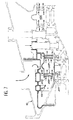
- a such design is shown in Figures 9 to 13, where the mixing device 400 is present under shape of a ring surrounding a low turbine pressure 401 whose stator 402 must be cooled.
- mixing device 400 is composed of two sheets 403 and 404 stamped and joined to each other then to enclose chambers 405, 406, 407 and 408 successive circulars and of polygonal section.
- the mixing device 400 is supplied with gas by a supply line 411 at least: as mounting of the mixing device is easier if it is built in two semicircular parts, we will use two supply lines in total if these semicircular parts remain disjoint when the machine is mounted, and either two conduits only one if these parts are joined together by junction flanges so that rooms 405 to 408 extend over one tower full.
- the construction with disjoint parts is more simple but not as good because part of the machine is insufficiently cooled at the junctions between the blowing device housings 400, and ventilation irregularities and therefore deformation of the stator 402 can appear from one half to the other of the device 400.
- Figure 10 shows that the principle of the previous embodiments is retained: if there is only one supply conduit 411 which joined the first chamber 405, there are two conduits 412 joining rooms 405 and 406 and four conduits 413 joining rooms 406 to rooms 407 and 408, the conduits 413 being pierced with lateral orifices 414 crossing the third room 407.
- This connection design applies to one half blower 400 and is repeated for the other half; others are possible, with numbers of chambers and connecting pipes different, depending on the angular extension of the rooms.
- Figure 11 shows the mixing device 400 isolated. We see that rooms 405 to 408 have decreasing sections, which is justified by the flow ever weaker gas reaching them and travels; Figures 12 and 13 show that the conduits 412 are much wider than the conduits 413 because of their smaller number and larger flow passing there.
- Conduits 412 and 413 play perfectly the role of the orifices making the rooms communicate other achievements and are only needed reason for the spacing of the rooms in this production.
- FIG. 10 represents partitions 414 and 415 which respectively divide the last two rooms 407 and 408 in compartments in each which leads only one of the conduits 413. This provision further promotes equalization of flow rates and ventilation air for each of the rooms.
- Figure 11 shows one of the flanges 416 of junction with the other semi-circular half of the device mixer 400.
Landscapes
- Engineering & Computer Science (AREA)
- Mechanical Engineering (AREA)
- General Engineering & Computer Science (AREA)
- Turbine Rotor Nozzle Sealing (AREA)
Claims (14)
- Kühlgaskrümmer in einem Turbotriebwerk, der sich um mindestens einen Statorring herum erstreckt und mehrere Kammern (12, 14, 15, 312, 313) umfasst, die in Achsrichtung aufeinander folgen, analoge aufrechte Querschnitte aufweisen und durch Trennwände (16, 17, 309, 310, 311) abgegrenzt sind, durch die Öffnungen (11, 16, 17, 18, 111, 324, 325, 326) verlaufen,
dadurch gekennzeichnet, dass die Kammern (12, 14, 15, 312, 313) durch die Trennwände hindurch mittels der Öffnungen (16, 17, 324, 325, 326), die in Strömungsrichtung des Gases von einer Trennwand zur nächsten stets zahlreicher sind, miteinander verbunden sind, wobei die Trennwände zwischen den Kammern angeordnete Trennwänden umfassen, die im wesentlichen parallel zueinander angeordnet sind. - Kühlgaskrümmer nach Anspruch 1,
dadurch gekennzeichnet, dass die Anzahlen der Öffnungen von einer Trennwand zur nächsten in geometrischer Abstufung vorgesehen sind. - Kühlgaskrümmer nach Anspruch 1,
dadurch gekennzeichnet, dass die Öffnungen von einer Trennwand zur nächsten jeweils in doppelter Anzahl vorgesehen sind. - Kühlgaskrümmer nach Anspruch 1,
dadurch gekennzeichnet, dass die Kammern (12, 14, 15) ringförmig ausgeführt und durch in dem Triebwerk quer verlaufende und kranzförmig ausgeführte Trennwände voneinander getrennt sind. - Kühlgaskrümmer nach Anspruch 1,
dadurch gekennzeichnet, dass die Kammern (327, 312, 313, 328) im wesentlichen ringförmig ausgeführt und durch im wesentlichen zylindrische und konzentrische Trennwände (309, 310, 311) voneinander getrennt sind. - Kühlgaskrümmer nach Anspruch 1,
dadurch gekennzeichnet, dass er eine Kammer zur Wärmeeinstellung (6) aufweist, die durch den Ring (3), eine der genannten Trennwände und durch parallele Raumteilerwände (7), die mit dem Ring verbunden sind und sich bis zu dieser Trennwand erstrecken, umgrenzt wird, wobei durch die Raumteilerwände hindurch Auslassöffnungen (20) verlaufen. - Kühlgaskrümmer nach Anspruch 1,
dadurch gekennzeichnet, dass der Ring (3) mit Raumteilerwänden (207, 320) verbunden ist, durch die gewundene Öffnungen (208, 211, 212, 321) verlaufen, durch die hindurch das Gas durch die Raumteilerwände gelangt. - Kühlgaskrümmer nach Anspruch 7,
dadurch gekennzeichnet, dass die Raumteilerwände von zwei parallelen Häuten (209, 210, 320) gebildet werden, die durch eine Rille (208, 321) voneinander getrennt sind. - Kühlgaskrümmer nach Anspruch 8,
dadurch gekennzeichnet, dass die Kammern und die Trennwände aus aufeinandergefügten Hauben bestehen. - Kühlgaskrümmer nach Anspruch 9,
dadurch gekennzeichnet, dass Abschnitte (322) der Hauben zumindest in manchen der Rillen (321) in Eingriff sind. - Kühlgaskrümmer in einem Turbotriebwerk, der sich um mindestens einen Statorring herum erstreckt und mehrere Kammern (405, 406, 407) umfasst, die in Achsrichtung parallel angeordnet sind, analoge Ausdehnungen haben, und durch welche Öffnungen (409) zum Statorring hin verlaufen,
dadurch gekennzeichnet, dass die Kammern kleiner werdende aufrechte Querschnitte aufweisen und durch Leitungen (412, 413) miteinander verbunden sind, die in Strömungsrichtung des Gases von einer Kammer zur nächsten stets zahlreicher sind. - Kühlgaskrümmer nach Anspruch 11,
dadurch gekennzeichnet, dass die Anzahlen der Leitungen von einer Kammerverbindung zur nächsten in geometrischer Abstufung vorgesehen sind. - Kühlgaskrümmer nach Anspruch 12,
dadurch gekennzeichnet, dass die Leitungen von einer Kammerverbindung zur nächsten jeweils in doppelter Anzahl vorgesehen sind. - Kühlgaskrümmer nach Anspruch 11,
dadurch gekennzeichnet, dass die Kammern in Bereiche unterteilt sind, in die jeweils eine der Leitungen mündet, die zu einer in Strömungsrichtung des Gases vorherigen Kammer führt.
Applications Claiming Priority (2)
| Application Number | Priority Date | Filing Date | Title |
|---|---|---|---|
| FR9607978 | 1996-06-27 | ||
| FR9607978A FR2750451B1 (fr) | 1996-06-27 | 1996-06-27 | Dispositif de soufflage de gaz de reglage de jeux dans une turbomachine |
Publications (2)
| Publication Number | Publication Date |
|---|---|
| EP0816639A1 EP0816639A1 (de) | 1998-01-07 |
| EP0816639B1 true EP0816639B1 (de) | 2002-05-29 |
Family
ID=9493461
Family Applications (1)
| Application Number | Title | Priority Date | Filing Date |
|---|---|---|---|
| EP97401486A Expired - Lifetime EP0816639B1 (de) | 1996-06-27 | 1997-06-26 | Kühlgaskrümmer für Dichtungsspaltregelung einer Turbomaschine |
Country Status (5)
| Country | Link |
|---|---|
| US (1) | US5980201A (de) |
| EP (1) | EP0816639B1 (de) |
| CA (1) | CA2209297A1 (de) |
| DE (1) | DE69712831T2 (de) |
| FR (1) | FR2750451B1 (de) |
Families Citing this family (32)
| Publication number | Priority date | Publication date | Assignee | Title |
|---|---|---|---|---|
| EP1079068A3 (de) * | 1999-08-27 | 2004-01-07 | General Electric Company | Verbindungsmuffe für den Kühlkreislauf eines Turbinenrotors |
| FR2816352B1 (fr) * | 2000-11-09 | 2003-01-31 | Snecma Moteurs | Ensemble de ventilation d'un anneau de stator |
| US6454529B1 (en) * | 2001-03-23 | 2002-09-24 | General Electric Company | Methods and apparatus for maintaining rotor assembly tip clearances |
| WO2004090291A1 (de) * | 2003-04-07 | 2004-10-21 | Alstom Technology Ltd | Turbomaschine |
| DE10352089A1 (de) * | 2003-11-07 | 2005-06-09 | Alstom Technology Ltd | Verfahren zum Betreiben einer Turbomaschine, und Turbomaschine |
| DE102005035540A1 (de) * | 2005-07-29 | 2007-02-01 | Mtu Aero Engines Gmbh | Vorrichtung zur aktiven Spaltkontrolle für eine Strömungsmaschine |
| US7740443B2 (en) * | 2006-11-15 | 2010-06-22 | General Electric Company | Transpiration clearance control turbine |
| US8197186B2 (en) * | 2007-06-29 | 2012-06-12 | General Electric Company | Flange with axially extending holes for gas turbine engine clearance control |
| US8393855B2 (en) * | 2007-06-29 | 2013-03-12 | General Electric Company | Flange with axially curved impingement surface for gas turbine engine clearance control |
| GB2469490B (en) * | 2009-04-16 | 2012-03-07 | Rolls Royce Plc | Turbine casing cooling |
| EP2243933A1 (de) * | 2009-04-17 | 2010-10-27 | Siemens Aktiengesellschaft | Gehäuseteil, insbesondere einer Turbomaschine |
| US20130149107A1 (en) * | 2011-12-08 | 2013-06-13 | Mrinal Munshi | Gas turbine outer case active ambient cooling including air exhaust into a sub-ambient region of exhaust flow |
| US9664062B2 (en) * | 2011-12-08 | 2017-05-30 | Siemens Energy, Inc. | Gas turbine engine with multiple component exhaust diffuser operating in conjunction with an outer case ambient external cooling system |
| US8894359B2 (en) * | 2011-12-08 | 2014-11-25 | Siemens Aktiengesellschaft | Gas turbine engine with outer case ambient external cooling system |
| US10094285B2 (en) * | 2011-12-08 | 2018-10-09 | Siemens Aktiengesellschaft | Gas turbine outer case active ambient cooling including air exhaust into sub-ambient cavity |
| US9085982B2 (en) * | 2012-03-19 | 2015-07-21 | Mitsubishi Hitachi Power Systems, Ltd. | Gas turbine |
| JP5868802B2 (ja) * | 2012-07-20 | 2016-02-24 | 株式会社東芝 | タービン |
| US9598974B2 (en) * | 2013-02-25 | 2017-03-21 | Pratt & Whitney Canada Corp. | Active turbine or compressor tip clearance control |
| US9279339B2 (en) | 2013-03-13 | 2016-03-08 | Siemens Aktiengesellschaft | Turbine engine temperature control system with heating element for a gas turbine engine |
| DE102015215144B4 (de) * | 2015-08-07 | 2017-11-09 | MTU Aero Engines AG | Vorrichtung und Verfahren zum Beeinflussen der Temperaturen in Innenringsegmenten einer Gasturbine |
| FR3041037B1 (fr) * | 2015-09-15 | 2018-08-17 | Safran Aircraft Engines | Dispositif de ventilation d'un carter de turbine d'une turbomachine |
| JP6563312B2 (ja) * | 2015-11-05 | 2019-08-21 | 川崎重工業株式会社 | ガスタービンエンジンの抽気構造 |
| US10329941B2 (en) * | 2016-05-06 | 2019-06-25 | United Technologies Corporation | Impingement manifold |
| FR3058459B1 (fr) * | 2016-11-04 | 2018-11-09 | Safran Aircraft Engines | Dispositif de refroidissement pour une turbine d'une turbomachine |
| EP3342991B1 (de) * | 2016-12-30 | 2020-10-14 | Ansaldo Energia IP UK Limited | Prallplatten für kühlung in einer gasturbine |
| US10422237B2 (en) * | 2017-04-11 | 2019-09-24 | United Technologies Corporation | Flow diverter case attachment for gas turbine engine |
| US10914187B2 (en) * | 2017-09-11 | 2021-02-09 | Raytheon Technologies Corporation | Active clearance control system and manifold for gas turbine engine |
| EP3569822A1 (de) * | 2018-05-15 | 2019-11-20 | Siemens Aktiengesellschaft | Rohrverbindung für eine strömungsmaschine |
| CN109653813B (zh) * | 2018-11-27 | 2019-08-23 | 中国航发沈阳发动机研究所 | 一种变几何涡轮冷气流路结构 |
| FR3096084B1 (fr) * | 2019-05-16 | 2021-04-16 | Safran Aircraft Engines | Procédé et dispositif d’estimation d’une zone morte d’une vanne de décharge de turbomachine |
| US11215075B2 (en) * | 2019-11-19 | 2022-01-04 | Rolls-Royce North American Technologies Inc. | Turbine shroud assembly with flange mounted ceramic matrix composite turbine shroud ring |
| CN114542287A (zh) * | 2022-02-17 | 2022-05-27 | 中国航发沈阳发动机研究所 | 一种降低机匣壁面周向温度不均匀性的引气结构 |
Family Cites Families (9)
| Publication number | Priority date | Publication date | Assignee | Title |
|---|---|---|---|---|
| US4279123A (en) * | 1978-12-20 | 1981-07-21 | United Technologies Corporation | External gas turbine engine cooling for clearance control |
| GB2103294B (en) * | 1981-07-11 | 1984-08-30 | Rolls Royce | Shroud assembly for a gas turbine engine |
| US4573865A (en) * | 1981-08-31 | 1986-03-04 | General Electric Company | Multiple-impingement cooled structure |
| US4512712A (en) * | 1983-08-01 | 1985-04-23 | United Technologies Corporation | Turbine stator assembly |
| GB2236147B (en) * | 1989-08-24 | 1993-05-12 | Rolls Royce Plc | Gas turbine engine with turbine tip clearance control device and method of operation |
| US5100291A (en) * | 1990-03-28 | 1992-03-31 | General Electric Company | Impingement manifold |
| GB9027986D0 (en) * | 1990-12-22 | 1991-02-13 | Rolls Royce Plc | Gas turbine engine clearance control |
| FR2688539A1 (fr) * | 1992-03-11 | 1993-09-17 | Snecma | Stator de turbomachine comprenant des dispositifs de reglage de jeu entre le stator et les aubes du rotor. |
| US5399066A (en) * | 1993-09-30 | 1995-03-21 | General Electric Company | Integral clearance control impingement manifold and environmental shield |
-
1996
- 1996-06-27 FR FR9607978A patent/FR2750451B1/fr not_active Expired - Fee Related
-
1997
- 1997-06-18 US US08/877,903 patent/US5980201A/en not_active Expired - Fee Related
- 1997-06-23 CA CA002209297A patent/CA2209297A1/fr not_active Abandoned
- 1997-06-26 DE DE69712831T patent/DE69712831T2/de not_active Expired - Fee Related
- 1997-06-26 EP EP97401486A patent/EP0816639B1/de not_active Expired - Lifetime
Also Published As
| Publication number | Publication date |
|---|---|
| US5980201A (en) | 1999-11-09 |
| DE69712831D1 (de) | 2002-07-04 |
| FR2750451B1 (fr) | 1998-08-07 |
| CA2209297A1 (fr) | 1997-12-27 |
| EP0816639A1 (de) | 1998-01-07 |
| FR2750451A1 (fr) | 1998-01-02 |
| DE69712831T2 (de) | 2003-01-16 |
Similar Documents
| Publication | Publication Date | Title |
|---|---|---|
| EP0816639B1 (de) | Kühlgaskrümmer für Dichtungsspaltregelung einer Turbomaschine | |
| EP1134360B1 (de) | Verstellvorrichtung für den Durchmesser des Stators eines Gasturbinenwerks | |
| EP1586743B1 (de) | Turbinen-Mantelring | |
| CA2475081C (fr) | Dispositif de controle de jeu dans une turbine a gaz | |
| EP0636765B1 (de) | Kühlung von Turbinenrotorscheibe | |
| EP0177408B1 (de) | Vorrichtung für die automatische Regelung des Spiels einer Labyrinthdichtung einer Turbomaschine | |
| EP3587743B1 (de) | Vorrichtung zum kühlen eines turbotriebwerkgehäuses | |
| FR2552817A1 (fr) | Perfectionnements au refroidissement des rotors de turbines | |
| EP4118304A1 (de) | Turbomaschinenhohlschaufel | |
| EP0081405B1 (de) | Ringförmige luftgekühlte abreissbare Schaufeldichtung für eine Gasturbine oder einen Kompressor | |
| FR2490721A1 (fr) | Turbomachine dont les aubages mobile et fixe sont proteges par une carapace en ceramique | |
| EP2050930B1 (de) | Gekühlte Turbomaschinenschaufel | |
| FR2513695A1 (fr) | Aube mobile aerodynamiquement profilee et refrigeree pour moteur a turbine a gaz | |
| FR3067405A1 (fr) | Turbomachine et procede d'etancheite par soufflage d'air | |
| CA2833489C (fr) | Distributeur de turbine dans une turbomachine | |
| EP4150200B1 (de) | Turbomaschinenabgasgehäuse | |
| EP3999779B1 (de) | Brennkammer einer turbomaschine mit konstantem volumen | |
| FR3153108A1 (fr) | Système amélioré de refroidissement d’anneau fixe de turbine à gaz | |
| FR3101379A1 (fr) | Pressurisation d’enceinte de turbomachine avec de l’air provenant de la veine secondaire | |
| FR3164245A1 (fr) | Carter d’injection d’air de refroidissement d’un disque de rotor d’une turbine comprenant des espaces inter-canaux | |
| FR3055355A1 (fr) | Dispositif et procede de reglage de jeux entre un rotor et un stator concentrique d'une turbomachine | |
| FR3148622A1 (fr) | Composant de turbomachine, turbomachine l’ayant et procédé de fabrication de celui-ci | |
| FR3120918A1 (fr) | Refroidissement par ventilation d’une cavité autour d’un rotor de turbomachine | |
| EP4381174A1 (de) | Kühlmantel einer hohlen verteilerschaufel | |
| BE511285A (de) |
Legal Events
| Date | Code | Title | Description |
|---|---|---|---|
| PUAI | Public reference made under article 153(3) epc to a published international application that has entered the european phase |
Free format text: ORIGINAL CODE: 0009012 |
|
| 17P | Request for examination filed |
Effective date: 19970707 |
|
| AK | Designated contracting states |
Kind code of ref document: A1 Designated state(s): DE FR GB |
|
| AKX | Designation fees paid |
Free format text: DE FR GB |
|
| RBV | Designated contracting states (corrected) |
Designated state(s): DE FR GB |
|
| 17Q | First examination report despatched |
Effective date: 20001019 |
|
| GRAG | Despatch of communication of intention to grant |
Free format text: ORIGINAL CODE: EPIDOS AGRA |
|
| GRAG | Despatch of communication of intention to grant |
Free format text: ORIGINAL CODE: EPIDOS AGRA |
|
| GRAH | Despatch of communication of intention to grant a patent |
Free format text: ORIGINAL CODE: EPIDOS IGRA |
|
| GRAH | Despatch of communication of intention to grant a patent |
Free format text: ORIGINAL CODE: EPIDOS IGRA |
|
| RAP1 | Party data changed (applicant data changed or rights of an application transferred) |
Owner name: SNECMA MOTEURS |
|
| GRAA | (expected) grant |
Free format text: ORIGINAL CODE: 0009210 |
|
| AK | Designated contracting states |
Kind code of ref document: B1 Designated state(s): DE FR GB |
|
| REG | Reference to a national code |
Ref country code: GB Ref legal event code: FG4D Free format text: NOT ENGLISH |
|
| REF | Corresponds to: |
Ref document number: 69712831 Country of ref document: DE Date of ref document: 20020704 |
|
| GBT | Gb: translation of ep patent filed (gb section 77(6)(a)/1977) |
Effective date: 20020720 |
|
| PLBE | No opposition filed within time limit |
Free format text: ORIGINAL CODE: 0009261 |
|
| STAA | Information on the status of an ep patent application or granted ep patent |
Free format text: STATUS: NO OPPOSITION FILED WITHIN TIME LIMIT |
|
| 26N | No opposition filed |
Effective date: 20030303 |
|
| PGFP | Annual fee paid to national office [announced via postgrant information from national office to epo] |
Ref country code: FR Payment date: 20050524 Year of fee payment: 9 |
|
| PGFP | Annual fee paid to national office [announced via postgrant information from national office to epo] |
Ref country code: GB Payment date: 20050527 Year of fee payment: 9 Ref country code: DE Payment date: 20050527 Year of fee payment: 9 |
|
| REG | Reference to a national code |
Ref country code: FR Ref legal event code: CD |
|
| PG25 | Lapsed in a contracting state [announced via postgrant information from national office to epo] |
Ref country code: GB Free format text: LAPSE BECAUSE OF NON-PAYMENT OF DUE FEES Effective date: 20060626 |
|
| PG25 | Lapsed in a contracting state [announced via postgrant information from national office to epo] |
Ref country code: DE Free format text: LAPSE BECAUSE OF NON-PAYMENT OF DUE FEES Effective date: 20070103 |
|
| GBPC | Gb: european patent ceased through non-payment of renewal fee |
Effective date: 20060626 |
|
| REG | Reference to a national code |
Ref country code: FR Ref legal event code: ST Effective date: 20070228 |
|
| PG25 | Lapsed in a contracting state [announced via postgrant information from national office to epo] |
Ref country code: FR Free format text: LAPSE BECAUSE OF NON-PAYMENT OF DUE FEES Effective date: 20060630 |