EP0816629B1 - Verfahren und Einrichtung zur Echtzeit-Einschätzung von mindestens eines Parameters, der mit dem Bohrfortschritt eines Bohrwerkzeuges zusammenhängt - Google Patents
Verfahren und Einrichtung zur Echtzeit-Einschätzung von mindestens eines Parameters, der mit dem Bohrfortschritt eines Bohrwerkzeuges zusammenhängt Download PDFInfo
- Publication number
- EP0816629B1 EP0816629B1 EP97401297A EP97401297A EP0816629B1 EP 0816629 B1 EP0816629 B1 EP 0816629B1 EP 97401297 A EP97401297 A EP 97401297A EP 97401297 A EP97401297 A EP 97401297A EP 0816629 B1 EP0816629 B1 EP 0816629B1
- Authority
- EP
- European Patent Office
- Prior art keywords
- model
- string
- displacement
- reduced
- account
- Prior art date
- Legal status (The legal status is an assumption and is not a legal conclusion. Google has not performed a legal analysis and makes no representation as to the accuracy of the status listed.)
- Expired - Lifetime
Links
Images


Classifications
-
- E—FIXED CONSTRUCTIONS
- E21—EARTH OR ROCK DRILLING; MINING
- E21B—EARTH OR ROCK DRILLING; OBTAINING OIL, GAS, WATER, SOLUBLE OR MELTABLE MATERIALS OR A SLURRY OF MINERALS FROM WELLS
- E21B44/00—Automatic control systems specially adapted for drilling operations, i.e. self-operating systems which function to carry out or modify a drilling operation without intervention of a human operator, e.g. computer-controlled drilling systems; Systems specially adapted for monitoring a plurality of drilling variables or conditions
-
- E—FIXED CONSTRUCTIONS
- E21—EARTH OR ROCK DRILLING; MINING
- E21B—EARTH OR ROCK DRILLING; OBTAINING OIL, GAS, WATER, SOLUBLE OR MELTABLE MATERIALS OR A SLURRY OF MINERALS FROM WELLS
- E21B45/00—Measuring the drilling time or rate of penetration
Definitions
- the present invention relates to the field of measurements during drilling, in particular measures concerning the displacement of a drilling tool attached to the end of a drill string.
- the method according to the invention provides a solution for estimate in particular the instantaneous speed of rotation of the tool at the bottom of the well, said estimates being obtained by means of a calculation program taking into account measurements taken at the top of the drill string, i.e. substantially on the surface of the ground, generally by means of sensors or an instrumented fitting located in the neighborhood of the means for rotating the lining.
- the information contained in the surface measurements does not alone are not enough to solve the problem posed, that is to say knowing the instantaneous movements of the tool by knowing the instantaneous movements of the surface trim.
- the surface measurement information must be supplemented by independent information of another kind which takes into account the structure of the drill string and its behavior between the bottom and the surface: this is the role of the knowledge which establishes the theoretical relationships between the bottom and the surface.
- the methodology of the present invention uses the conjunction of such a model, defined a priori, and surface measurements acquired in real time.
- the model can take into account essentially the rotational displacements and said reduced model can calculate in real time the instantaneous speed of rotation of the tool of drilling, said parameter measured at the surface can be taken from at least: the speed of packing rotation or torque.
- the reduced model can be refined by self-adaptive filtering which minimizes the difference between an actual measurement of a parameter related to the displacement of the lining in surface and the corresponding output obtained by said reduced model.
- Filtering can take into account the torque measured at the surface or the speed of rotation measured at the surface.
- the invention also relates to a system for estimating the effective displacement. of a drilling tool attached to the end of a drill string and rotated in a well by means of drive located on the surface, in which an installation of calculation includes means for non-linear physical modeling of the drilling process based on general mechanical equations.
- the parameters of said means modeling are identified by taking into account the parameters of said well and said lining, and the calculation installation includes means for linearizing said model around an operating point, means for reducing said linearized model so to keep only some of the eigen modes of the state matrix of said model, means for calculating, in real time, the displacement of the drilling tool using the means once linearized and reduced and means of measuring at least one parameter linked to the displacement of the lining on the surface.
- the modeling means may take into account only the torsion, and the parameters can be the speed of rotation and / or the torque.
- FIG. 1 illustrates a drilling rig on which we will operate the invention.
- the surface installation comprises a lifting device 1 comprising a lifting tower 2, a winch 3 which allow the displacement of a drilling hook 4.
- Under the drill hook are suspended drive means 5 for rotating the assembly of the drill string 6 placed in the well 7.
- These drive means can be of the drive rod or kelly type coupled to a rotation table 8 and the mechanical motorizations, or of the type motorized drive head or "power swivel" suspended directly from the hook and guided longitudinally in the tower.
- the drill string 6 is conventionally constituted by rods of drilling 10, of part 11 commonly called BHA for "Bottom Hole Assembly” mainly comprising drill rods, a drilling tool 12 in contact with the land being drilled.
- BHA Bottom Hole Assembly
- the well 7 is filled with a fluid, called a drilling fluid, which circulates from the surface at the bottom through the inner channel of the drill string and rises to the surface by the annular space between the walls of the well and the drill string.
- an instrumented fitting can be inserted 13 between the drive means and the top of the lining.
- This fitting allows measure the torque, the speed of rotation, possibly the longitudinal displacement of the top of the filling.
- These so-called surface measurements are transmitted by cable or radio towards an electronic installation of recording, processing, display, not shown here.
- other sensors such as a tachometer on the rotation table to measure the speed of rotation and a measurement of the torque on the motorized device, if the accuracy of the measurements thus obtained is sufficient.
- Part 11 of the BHA may more specifically include, drill collars, stabilizers, a shock absorber, and a second instrumented connector 14 which will not used only to experimentally control the present invention by allowing the comparison between the displacement of the drilling tool 12 actually measured by the instrumented fitting 14 and the estimated displacement thanks to the implementation of this invention. It is therefore clear that the application of the present invention does not use instrumented fitting placed at the bottom of the well.
- the driller who conducts a drilling operation with the devices described in the Figure 1 has three main possible actions, which are therefore the command variables possible to control the drilling process. These are, the weight on the tool which is adjusted by the winch which controls the position of the hook, the speed of rotation of the table rotation or equivalent, and the flow of injected drilling fluid.
- the described model will treat the drill string as a one-dimensional element vertical. Only rotational displacements will be considered, vertical displacements and lateral being neglected.
- Figure 2 shows the block diagram of the model; here of twist. It's a model classic with finite differences which comprises several tens of meshes represented by blocks 20. Each mesh represents a part of the drill string, composed inter alia of drill rods and drill rods. It is a figured mass-spring-damping triplet by the diagrams referenced 21, 22, 23. Each block is provided with two inputs and outputs represented by the pairs of arrows 24 and 25 which represent the input and output and input and output rotational speeds. This representation shows the way to digitally connect several rods (or meshes) as we connect physically the packing rods.
- Block 26 represents the boundary conditions at the head of the resulting drill string of the drilling rig.
- Block 27 represents the friction law of the tool / ground contact determining the boundary conditions at the bottom of the well. This is a type power dissipator resistant couple.
- the different curves 28 represent a nonlinear law of tool / rock interaction, depending on the instantaneous speed of the tool (input 29) of the resisting torque (outlet 30) and weight on the tool (inlet 31).
- This model is validated using data recorded on site using the instrumented bottom and surface fittings.
- the torsion model thus obtained is generally of high order, that is to say of around 50 to 100 to reproduce reality with sufficient finesse.
- the torsion model retains the same high order. analysis eigen modes of the torsion model allows to quantify the contribution of each fashion on exits of interest. We only keep the relevant modes; that is to say those who have a notable influence on the dynamic behavior represented by said outputs.
- the reduction method used is the singular disturbance method. It consists in keeping from the state matrix and from the command matrix, the lines and the columns corresponding to the modes to keep. To keep static gains, the modes Rapids are replaced by their static value, which has the consequence of introducing a direct matrix.
- the method assumes that the fast modes take their equilibrium in a time negligible, that is to say that they are established instantaneously (quasi-static hypothesis).
- FIG. 3 shows the block diagram of a loop-type estimation system opened.
- Block 40 shows diagrammatically the means for measuring surface parameters, here the speed of rotation of the lining Vms measured at the table or at the motorized injection head, and the torque Cms also measured at the surface.
- Block 41 represents the scale model which simulates the physical model of nonlinear torsion by calculating the transfer function between the input (Vms) and the outputs Ces, Cef and Vef representing respectively the torque of estimated area, estimated bottom torque and estimated bottom speed.
- the transfer function is always an approximation of reality and any mismatch between the model and the actual drilling process can create a divergence between the estimated values and the real values by integration of the differences. Also, in most cases, it is advantageous to carry out a readjustment, or readjustment, using at least one comparison between a series of values from an estimated output and the same actually measured series. In this example, the linear estimator is readjusted from the surface torque.
- the estimation technique is based on the filtering principles of Luenberger and Kalman ("Automatic linear systems" by P. De Larminat and Y. Thomas-Flammarion science; Paris IV, 1975).
- the principle of a linear estimator can be illustrated by FIG. 4 where the measurement of the torque Cms and the estimated value Ces are compared in the means 42, the difference between these two values being injected into an adapter 43 in real time.
- the objective here is to reconstruct the exits as faithfully as possible rather than having an exact model.
- state registration consists in performing a weighting between the states predicted by the model at time t and the states reconstructed from only measured outputs. This weighting is not a simple average, but it takes into account the degree of precision of the estimates of the states obtained by its two channels independent.
- the measured torque can be used as input Cms and perform the readjustment by the rotation speed.
- the state registration technique introduces a slaving of Cms measured on these estimated.
- the modal study of the knowledge model locates the five first modes at 0.344 Hz, 1.86 Hz, 3.61 Hz, 5.37 Hz, 7.12 Hz.
- the final choice of reduction order can be made by comparing the results obtained with a model reduced to order 2 and a model reduced to order 4.
- the reduced estimation model must, preferably meet the technological constraints of real time.
- Block 50 represents a physical model representing a rotary drilling process, for example illustrated in Figure 2. This model takes into account account for a determined operating situation, in particular by receiving the mechanical characteristics of the drill string used, symbolization referenced 51, well and surface conditions, symbolization referenced 52, and friction laws, symbolized by reference 53.
- Block 54 represents the main torsion model once linearized and reduced as described above. All these steps gathered under the DF brace run in delayed time compared to the progress of the process rotary drilling, the other steps gathered under the TR brace are executed in time real.
- Block 55 is directly what has been called the estimator.
- Means of measure 56 placed on the top of the drill string give the torque measurements and speed of rotation at the top of the rods, i.e. at the surface. These surface measurements are taken into account in the estimator, as described above, to give a estimation of the displacement values of the drilling tool, in particular the speed of rotation of the Vef drilling tool.
- the present invention is advantageously implemented on a construction site drilling in order to have as precise an estimate as possible of the rotation speed of the drilling tool in real time, using only surface measurements, in particular the rotational speed of conventional means for rotating the gasket drilling, and a surface installation equipped with electronic and computer means. It is very interesting to have an estimate of the background parameters in order to detect, and even to prevent known malfunctions, for example the so-called behavior of "stick-slip” characterized by very sensitive variations in the speed of rotation of the tool at bottom while it is driven through a drill string set rotation from the surface at a substantially constant speed. Tool speed can vary between a practically zero speed and a value of the speed of rotation very higher than the speed applied to the surface. This may have consequences detrimental to the life of the tools, increasing the mechanical fatigue of the train of rods and the frequency of connection breaks.
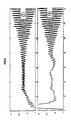
- Figure 6 shows a record F of the speed of rotation of a tool drilling, recording made from bottom sensors, for example using means described in document FR / 92-02273.
- Said means allow measurements of rotational speed and surface torque, synchronized with speed measurements of rotation and torque at the bottom. Area measurements are used as inputs to the estimator according to the invention, and after having carried out all the necessary calculation steps, we obtain the record S corresponding to the speed of the tool at the bottom estimated by the estimator according to the invention.
- the diagrams F and S are plotted with, in abscissa the time and on the ordinate the speed of rotation of the tool. We can thus compare the measurement actually performed F with the values S obtained by the estimator according to the invention.
- the present invention is also applicable to the estimate of the instantaneous speed of rotation of elements included in the gasket drilling, elements which can be located at a certain distance from the drilling tool.
Landscapes
- Life Sciences & Earth Sciences (AREA)
- Engineering & Computer Science (AREA)
- Geology (AREA)
- Mining & Mineral Resources (AREA)
- Physics & Mathematics (AREA)
- Environmental & Geological Engineering (AREA)
- Fluid Mechanics (AREA)
- General Life Sciences & Earth Sciences (AREA)
- Geochemistry & Mineralogy (AREA)
- Earth Drilling (AREA)
Claims (5)
- Verfahren zur Abschätzung der effektiven Verschiebung eines am Ende einer Bohrstangengarnitur (6) angebrachten Bohrwerkzeuges (12), das mittels an der Bodenoberfläche angebrachten Antriebsmittel (8) in einem Bohrloch (7) in drehende Bewegung gesetzt wird, in welchem ein auf allgemeinen Mechanikgleichungen beruhendes, nichtlinear physisches Modell (50) des Bohrungsvorganges verwendet wird, dadurch gekennzeichnet, daß die folgenden Stufen durchgeführt werden :die Parameter des besagten Modells werden durch Berücksichtigung der Parameter des besagten Bohrlochs und der besagten Garnitur (51, 52, 53) identifiziert,das besagte Modell wird um einen Betriebspunkt linearisiert,das besagte linearisierte Modell wird reduziert, wobei nur einige Eigenmoden der Zustandsmatrix des besagten Modells behalten werden,die Verschiebung des Werkzeuges wird mittels des reduzierten Modells (54) und wenigstens eines an der Oberfläche gemeßten Parameters in Echtzeit berechnet, daß das besagte Modell hauptsächlich die Drehverschiebungen berücksichtigt und das besagte reduzierte Modell die Augenblicksdrehgeschwindigkeit des Bohrwerzeuges in Echtzeit berechnet, wobei der an der Oberfläche gemeßte Parameter wenigstens unter den Folgenden gewählt wird: die Drehgeschwindigkeit der Garnitur oder das an der Oberfläche gemeßte Moment.
- Verfahren gemäß Anspruch 1, in welchem das reduzierte Modell durch selbsteinstellendes Filtern verfeinert wird, wobei der Unterschied zwischen einer effektiven Messung eines mit der Verschiebung der Garnitur an der Oberfläche verbundenen Parameters und der mittels des reduzierten Modells erhaltenen entsprechenden Ausgabe minimisiert wird.
- Verfahren gemäß Anspruch 2, in welchem das besagte Filtern das an der Oberfläche gemeßte Moment berücksichtigt.
- Verfahren gemäß Anspruch 3, in welchem das besagte Filtern die an der Oberfläche gemeßte Geschwindigkeit berücksichtigt.
- System zur Abschätzung der effektiven Verschiebung eines am Ende einer Bohrstangengarnitur (6) angebrachten Bohrwerkzeuges (12), das mittels an der Bodenoberfläche angebrachten Antriebsmittel (8) in einem Bohrloch (7) in drehende Bewegung gesetzt wird, in welchem eine Rechenanlage (9) Mittel zur nichtlinearen physische Modellierung des Bohrungvorganges beträgt, dadurch gekennzeichnet, daß die Parameter der besagten Modellierungsmittel durch Berücksichtigung der Parameter des besagten Bohrloches und der besagten Garnitur identifiziert werden, daß die Rechenanlage Mittel zur Linearisierung des besagten Modells um einen Betriebspunkt beträgt, Mittel zur Reduzierung des besagten linearisierten Modells um nur einige Eigenmoden der Zustandsmatrix des besagten Modells zu behalten, Mittel zum Echtzeitrechnen der Bohrwerkzeugverschiebung mittels den linearisierten und reduzierten Modellierungsmittel, und Mittel zur Messung von wenigstens einem mit der Verschiebung der Garnitur an der Oberfläche verbundenen Parameter (13): Drehgeschwindigkeit und/oder Moment, und in welchem die Modellierungsmittel nur die Verdrehung berücksichtigen.
Applications Claiming Priority (2)
| Application Number | Priority Date | Filing Date | Title |
|---|---|---|---|
| FR9607915A FR2750160B1 (fr) | 1996-06-24 | 1996-06-24 | Methode et systeme d'estimation en temps reel d'au moins un parametre lie au deplacement d'un outil de forage |
| FR9607915 | 1996-06-24 |
Publications (2)
| Publication Number | Publication Date |
|---|---|
| EP0816629A1 EP0816629A1 (de) | 1998-01-07 |
| EP0816629B1 true EP0816629B1 (de) | 2003-05-14 |
Family
ID=9493416
Family Applications (1)
| Application Number | Title | Priority Date | Filing Date |
|---|---|---|---|
| EP97401297A Expired - Lifetime EP0816629B1 (de) | 1996-06-24 | 1997-06-09 | Verfahren und Einrichtung zur Echtzeit-Einschätzung von mindestens eines Parameters, der mit dem Bohrfortschritt eines Bohrwerkzeuges zusammenhängt |
Country Status (5)
| Country | Link |
|---|---|
| US (1) | US5852235A (de) |
| EP (1) | EP0816629B1 (de) |
| CA (1) | CA2209056C (de) |
| FR (1) | FR2750160B1 (de) |
| NO (1) | NO972932L (de) |
Families Citing this family (21)
| Publication number | Priority date | Publication date | Assignee | Title |
|---|---|---|---|---|
| EP0870899A1 (de) * | 1997-04-11 | 1998-10-14 | Shell Internationale Researchmaatschappij B.V. | Bohreinrichtung mit reduzierter Stick-Slipneigung |
| US6327539B1 (en) | 1998-09-09 | 2001-12-04 | Shell Oil Company | Method of determining drill string stiffness |
| US6347292B1 (en) * | 1999-02-17 | 2002-02-12 | Den-Con Electronics, Inc. | Oilfield equipment identification method and apparatus |
| RU2183266C1 (ru) * | 2000-09-27 | 2002-06-10 | Общество с ограниченной ответственностью "ЮганскНИПИнефть" | Способ определения работоспособности породоразрушающего инструмента |
| EA018946B1 (ru) * | 2008-06-17 | 2013-11-29 | Эксонмобил Апстрим Рисерч Компани | Способы и системы для ослабления колебаний при бурении |
| WO2010059295A1 (en) | 2008-11-21 | 2010-05-27 | Exxonmobil Upstream Research Company | Methods and systems for modeling, designing, and conducting drilling operations that consider vibrations |
| PL2364397T3 (pl) | 2008-12-02 | 2013-06-28 | Nat Oilwell Varco Lp | Sposób i urządzenie do zmniejszenia zjawiska drgań ciernych |
| US8689906B2 (en) | 2008-12-02 | 2014-04-08 | National Oilwell Varco, L.P. | Methods and apparatus for reducing stick-slip |
| MY158575A (en) | 2009-08-07 | 2016-10-14 | Exxonmobil Upstream Res Co | Methods to estimate downhole drilling vibration indices from surface measurement |
| WO2011017626A1 (en) | 2009-08-07 | 2011-02-10 | Exxonmobil Upstream Research Company | Methods to estimate downhole drilling vibration amplitude from surface measurement |
| AU2013400710B2 (en) * | 2013-09-17 | 2016-12-15 | Halliburton Energy Services, Inc. | Removal of stick-slip vibrations in a drilling assembly |
| CN103941632B (zh) * | 2014-04-29 | 2016-08-24 | 西北工业大学 | 一种基于自适应法抑制钻杆粘滑振动的系统及方法 |
| US11225834B2 (en) * | 2015-04-29 | 2022-01-18 | Halliburton Energy Services, Inc. | Systems and methods for sensorless state estimation, disturbance estimation, and model adaption for rotary steerable drilling systems |
| US10317555B2 (en) | 2016-01-19 | 2019-06-11 | Halliburton Energy Services, Inc. | Method of minimizing tool response for downhole logging operations |
| EP3601727A1 (de) | 2017-03-31 | 2020-02-05 | ExxonMobil Upstream Research Company | Verfahren zum bohren von bohrlöchern unter verwendung einer für haft-gleit-schwingungsbedingungen optimierten bohrstranganordnung |
| US11536128B2 (en) | 2017-03-31 | 2022-12-27 | Exxonmobil Upstream Research Company | Method for drilling wellbores utilizing drilling parameters optimized for stick-slip vibration conditions |
| US10370902B2 (en) | 2017-04-04 | 2019-08-06 | Nabors Drilling Technologies Usa, Inc. | Downhole steering control apparatus and methods |
| US10648321B2 (en) | 2017-04-04 | 2020-05-12 | Nabors Drilling Technologies Usa, Inc. | Surface control system adaptive downhole weight on bit/torque on bit estimation and utilization |
| WO2019119107A1 (en) | 2017-12-23 | 2019-06-27 | Noetic Technologies Inc. | System and method for optimizing tubular running operations using real-time measurements and modelling |
| US11704453B2 (en) * | 2019-06-06 | 2023-07-18 | Halliburton Energy Services, Inc. | Drill bit design selection and use |
| US11748531B2 (en) | 2020-10-19 | 2023-09-05 | Halliburton Energy Services, Inc. | Mitigation of high frequency coupled vibrations in PDC bits using in-cone depth of cut controllers |
Family Cites Families (12)
| Publication number | Priority date | Publication date | Assignee | Title |
|---|---|---|---|---|
| US4794535A (en) * | 1986-08-18 | 1988-12-27 | Automated Decisions, Inc. | Method for determining economic drill bit utilization |
| US4845628A (en) * | 1986-08-18 | 1989-07-04 | Automated Decisions, Inc. | Method for optimization of drilling costs |
| FR2614360B1 (fr) * | 1987-04-27 | 1989-06-16 | Forex Neptune | Procede de mesure de la vitesse d'avancement d'un outil de forage |
| FR2645205B1 (fr) * | 1989-03-31 | 1991-06-07 | Elf Aquitaine | Dispositif de representation auditive et/ou visuelle des phenomenes mecaniques dans un forage et utilisation du dispositif dans un procede de conduite d'un forage |
| FR2666845B1 (fr) * | 1990-09-14 | 1997-01-10 | Elf Aquitaine | Procede de conduite d'un forage. |
| GB2264562B (en) * | 1992-02-22 | 1995-03-22 | Anadrill Int Sa | Determination of drill bit rate of penetration from surface measurements |
| FR2688026B1 (fr) * | 1992-02-27 | 1994-04-15 | Institut Francais Petrole | Systeme et methode d'acquisition de donnees physiques liees a un forage en cours. |
| US5305836A (en) * | 1992-04-08 | 1994-04-26 | Baroid Technology, Inc. | System and method for controlling drill bit usage and well plan |
| GB9216740D0 (en) * | 1992-08-06 | 1992-09-23 | Schlumberger Services Petrol | Determination of drill bit rate of penetration from surface measurements |
| GB9218836D0 (en) * | 1992-09-05 | 1992-10-21 | Schlumberger Services Petrol | Method for determining weight on bit |
| NO315670B1 (no) * | 1994-10-19 | 2003-10-06 | Anadrill Int Sa | Fremgangsmåte og anordning for måling av boretilstander ved kombinasjon avnedihulls- og overflatemålinger |
| US5581024A (en) * | 1994-10-20 | 1996-12-03 | Baker Hughes Incorporated | Downhole depth correlation and computation apparatus and methods for combining multiple borehole measurements |
-
1996
- 1996-06-24 FR FR9607915A patent/FR2750160B1/fr not_active Expired - Fee Related
-
1997
- 1997-06-09 EP EP97401297A patent/EP0816629B1/de not_active Expired - Lifetime
- 1997-06-23 US US08/880,801 patent/US5852235A/en not_active Expired - Lifetime
- 1997-06-23 CA CA002209056A patent/CA2209056C/fr not_active Expired - Fee Related
- 1997-06-23 NO NO972932A patent/NO972932L/no not_active Application Discontinuation
Also Published As
| Publication number | Publication date |
|---|---|
| FR2750160A1 (fr) | 1997-12-26 |
| CA2209056A1 (fr) | 1997-12-24 |
| CA2209056C (fr) | 2006-11-14 |
| FR2750160B1 (fr) | 1998-08-07 |
| EP0816629A1 (de) | 1998-01-07 |
| US5852235A (en) | 1998-12-22 |
| NO972932L (no) | 1997-12-29 |
| NO972932D0 (no) | 1997-06-23 |
Similar Documents
| Publication | Publication Date | Title |
|---|---|---|
| EP0816629A1 (de) | Verfahren und Einrichtung zur Echtzeit-Einschätzung von mindestens eines Parameters, der mit dem Bohrfortschritt eines Bohrwerkzeuges zusammenhängt | |
| EP1046781B1 (de) | Vorrichtung und Verfahren zum detektieren von longitudinalen Bewegungen eines Bohrgestänges | |
| EP0816630B1 (de) | Verfahren und Einrichtung zur Echtzeit-Einschätzung von mindestens eines Parameters, der mit dem Verhalten eines Bohrlochwerkzeuges zusammenhängt | |
| FR3057604B1 (fr) | Diagraphie mci améliorëe pour le traitement de mesures de fond de puits | |
| EP3936669B1 (de) | Verfahren, system und computerprogrammprodukt zur bestimmung von bodeneigenschaften | |
| FR2869067A1 (fr) | Systeme et procede de synthese de champ pour l'optimisation d'un dispositif de forage | |
| FR3043481A1 (de) | ||
| FR3077142A1 (fr) | Optimisation d’une longueur de référence à des fins de préservation de signal et traitement d’une longueur de référence à des fins de détection de vibration répartie | |
| FR2570757A1 (fr) | Procede et dispositif pour estimer les caracteristiques de formation de la formation exposee au fond d'un trou | |
| EP0125164A1 (de) | Verfahren zur Ermittlung der Eigenschaften einer flüssigkeitsführenden, unterirdischen Formation | |
| US20160177706A1 (en) | Formation fracturing potential using surrounding pore pressures | |
| FR3081026A1 (fr) | Optimisation BAYÉSIENNE BASÉE SUR L'APPRENTISSAGE pour optimiser les paramÈtres de forage POUVANT ÊTRE COMMANDÉS | |
| WO2012038647A1 (fr) | Procede d'estimation de parametres elastiques par inversion de mesures sismiques 4d | |
| FR3066224A1 (fr) | Procede et systeme pour forer un puits de forage et identifier une defaillance du trepan de forage par deconvolution des donnees de capteur | |
| FR3084102A1 (fr) | Ajustement du fonctionnement d’un outil de puits pour manipuler le taux de pénétration (rop) d’un trépan de forage sur la base de multiples prévisions de rop | |
| FR3039196A1 (de) | ||
| FR2611804A1 (fr) | Procede de controle des operations de forage d'un puits | |
| CA2805688A1 (fr) | Procede d'estimation de parametres elastiques par inversion de mesures sismiques 4d | |
| FR3152900A1 (fr) | Procédé, appareil, et système d’estimation de coordonnées d’une pointe de dent de godet, excavatrice, et support de stockage | |
| FR3034191B1 (fr) | Determination de pression de formation | |
| FR3035147A1 (de) | ||
| FR3076626A1 (fr) | Prediction de proprietes de roches sismiques en temps avance sur la base d'une analyse sismique 4d | |
| EP1341094B1 (de) | Verfahren zur Ermittlung eines räumlichen Qualitätsindexes für Regionaldaten | |
| EP3502751A1 (de) | Modellierungsverfahren eines sedimentbeckens | |
| WO2023061875A1 (fr) | Procede et dispositif de stabilisation d'un systeme de faille par injection controlee d'un fluide |
Legal Events
| Date | Code | Title | Description |
|---|---|---|---|
| PUAI | Public reference made under article 153(3) epc to a published international application that has entered the european phase |
Free format text: ORIGINAL CODE: 0009012 |
|
| AK | Designated contracting states |
Kind code of ref document: A1 Designated state(s): GB IT NL |
|
| 17P | Request for examination filed |
Effective date: 19980707 |
|
| AKX | Designation fees paid |
Free format text: GB IT NL |
|
| RBV | Designated contracting states (corrected) |
Designated state(s): GB IT NL |
|
| REG | Reference to a national code |
Ref country code: DE Ref legal event code: 8566 |
|
| 17Q | First examination report despatched |
Effective date: 20010313 |
|
| GRAH | Despatch of communication of intention to grant a patent |
Free format text: ORIGINAL CODE: EPIDOS IGRA |
|
| GRAH | Despatch of communication of intention to grant a patent |
Free format text: ORIGINAL CODE: EPIDOS IGRA |
|
| GRAH | Despatch of communication of intention to grant a patent |
Free format text: ORIGINAL CODE: EPIDOS IGRA |
|
| GRAA | (expected) grant |
Free format text: ORIGINAL CODE: 0009210 |
|
| AK | Designated contracting states |
Designated state(s): GB IT NL |
|
| REG | Reference to a national code |
Ref country code: GB Ref legal event code: FG4D Free format text: NOT ENGLISH |
|
| PGFP | Annual fee paid to national office [announced via postgrant information from national office to epo] |
Ref country code: GB Payment date: 20030602 Year of fee payment: 7 |
|
| GBT | Gb: translation of ep patent filed (gb section 77(6)(a)/1977) |
Effective date: 20030515 |
|
| PGFP | Annual fee paid to national office [announced via postgrant information from national office to epo] |
Ref country code: NL Payment date: 20030627 Year of fee payment: 7 |
|
| PLBE | No opposition filed within time limit |
Free format text: ORIGINAL CODE: 0009261 |
|
| STAA | Information on the status of an ep patent application or granted ep patent |
Free format text: STATUS: NO OPPOSITION FILED WITHIN TIME LIMIT |
|
| 26N | No opposition filed |
Effective date: 20040217 |
|
| PG25 | Lapsed in a contracting state [announced via postgrant information from national office to epo] |
Ref country code: GB Free format text: LAPSE BECAUSE OF NON-PAYMENT OF DUE FEES Effective date: 20040609 |
|
| PG25 | Lapsed in a contracting state [announced via postgrant information from national office to epo] |
Ref country code: NL Free format text: LAPSE BECAUSE OF NON-PAYMENT OF DUE FEES Effective date: 20050101 |
|
| GBPC | Gb: european patent ceased through non-payment of renewal fee |
Effective date: 20040609 |
|
| NLV4 | Nl: lapsed or anulled due to non-payment of the annual fee |
Effective date: 20050101 |
|
| PGFP | Annual fee paid to national office [announced via postgrant information from national office to epo] |
Ref country code: IT Payment date: 20070622 Year of fee payment: 11 |
|
| PG25 | Lapsed in a contracting state [announced via postgrant information from national office to epo] |
Ref country code: IT Free format text: LAPSE BECAUSE OF NON-PAYMENT OF DUE FEES Effective date: 20080609 |