EP3936669B1 - Verfahren, system und computerprogrammprodukt zur bestimmung von bodeneigenschaften - Google Patents
Verfahren, system und computerprogrammprodukt zur bestimmung von bodeneigenschaften Download PDFInfo
- Publication number
- EP3936669B1 EP3936669B1 EP21193959.0A EP21193959A EP3936669B1 EP 3936669 B1 EP3936669 B1 EP 3936669B1 EP 21193959 A EP21193959 A EP 21193959A EP 3936669 B1 EP3936669 B1 EP 3936669B1
- Authority
- EP
- European Patent Office
- Prior art keywords
- probe
- pumping
- soil
- pressure
- liquid injection
- Prior art date
- Legal status (The legal status is an assumption and is not a legal conclusion. Google has not performed a legal analysis and makes no representation as to the accuracy of the status listed.)
- Active
Links
Images




Classifications
-
- G—PHYSICS
- G01—MEASURING; TESTING
- G01N—INVESTIGATING OR ANALYSING MATERIALS BY DETERMINING THEIR CHEMICAL OR PHYSICAL PROPERTIES
- G01N15/00—Investigating characteristics of particles; Investigating permeability, pore-volume or surface-area of porous materials
- G01N15/08—Investigating permeability, pore-volume, or surface area of porous materials
- G01N15/082—Investigating permeability by forcing a fluid through a sample
- G01N15/0826—Investigating permeability by forcing a fluid through a sample and measuring fluid flow rate, i.e. permeation rate or pressure change
-
- E—FIXED CONSTRUCTIONS
- E02—HYDRAULIC ENGINEERING; FOUNDATIONS; SOIL SHIFTING
- E02D—FOUNDATIONS; EXCAVATIONS; EMBANKMENTS; UNDERGROUND OR UNDERWATER STRUCTURES
- E02D1/00—Investigation of foundation soil in situ
- E02D1/02—Investigation of foundation soil in situ before construction work
- E02D1/027—Investigation of foundation soil in situ before construction work by investigating properties relating to fluids in the soil, e.g. pore-water pressure, permeability
-
- E—FIXED CONSTRUCTIONS
- E02—HYDRAULIC ENGINEERING; FOUNDATIONS; SOIL SHIFTING
- E02D—FOUNDATIONS; EXCAVATIONS; EMBANKMENTS; UNDERGROUND OR UNDERWATER STRUCTURES
- E02D1/00—Investigation of foundation soil in situ
- E02D1/02—Investigation of foundation soil in situ before construction work
- E02D1/04—Sampling of soil
-
- E—FIXED CONSTRUCTIONS
- E21—EARTH OR ROCK DRILLING; MINING
- E21B—EARTH OR ROCK DRILLING; OBTAINING OIL, GAS, WATER, SOLUBLE OR MELTABLE MATERIALS OR A SLURRY OF MINERALS FROM WELLS
- E21B49/00—Testing the nature of borehole walls; Formation testing; Methods or apparatus for obtaining samples of soil or well fluids, specially adapted to earth drilling or wells
- E21B49/008—Testing the nature of borehole walls; Formation testing; Methods or apparatus for obtaining samples of soil or well fluids, specially adapted to earth drilling or wells by injection test; by analysing pressure variations in an injection or production test, e.g. for estimating the skin factor
-
- E—FIXED CONSTRUCTIONS
- E21—EARTH OR ROCK DRILLING; MINING
- E21B—EARTH OR ROCK DRILLING; OBTAINING OIL, GAS, WATER, SOLUBLE OR MELTABLE MATERIALS OR A SLURRY OF MINERALS FROM WELLS
- E21B7/00—Special methods or apparatus for drilling
- E21B7/20—Driving or forcing casings or pipes into boreholes, e.g. sinking; Simultaneously drilling and casing boreholes
-
- G—PHYSICS
- G01—MEASURING; TESTING
- G01N—INVESTIGATING OR ANALYSING MATERIALS BY DETERMINING THEIR CHEMICAL OR PHYSICAL PROPERTIES
- G01N33/00—Investigating or analysing materials by specific methods not covered by groups G01N1/00 - G01N31/00
- G01N33/24—Earth materials
Definitions
- the invention relates to a method and system for determining soil properties by use of pumping tests.
- the present invention relates to a pumping test that has enhanced results and requires less time and power.
- a pumping test is a test that is carried out either by injecting or extracting water from the soil.
- the present invention is described in terms of liquid injection; however, a skilled person would easily understand that similar principles apply to liquid extraction, which however is not forming part of the invention.
- An aquifer is a geological unit sufficiently permeable to yield quantities of water to wells.
- Aquifers can be classified in categories such as confined aquifers, unconfined aquifers, leaky aquifers.
- the most common aquifers are unconsolidated sand and gravels, but permeable sedimentary rocks such as sandstone and limestone, and heavily fractured or weathered volcanic and crystalline rocks can also be classified as aquifers.
- a classic pumping test is commonly employed to determine hydro-geological parameters and/or characterize a system of aquifers, aquitards and flow system boundaries.
- An aquifer can be evaluated and the characteristics of the aquifer (e.g. hydraulic conductivity, permeability, storativity, etc.) can be quantified by conducting a pumping test.
- the effect of constant pumping of a liquid is analyzed by observation of the response or result on the aquifer in the form of a drawdown in observation wells.
- a classic pumping test is conducted by pumping water from one extraction well at a constant rate and for an extended period of time of at least one day (usually multiple days), while simultaneously measuring the water levels in nearby observation wells prior to, during and after pumping.
- the data can then be used to obtain resulting drawdown and recovery curves.
- the hydraulic pressure surrounding the well in the aquifer that feeds the well declines as a result of water being pumped from the extraction well. This will show up as drawdown in observation wells.
- the drawdown will increase with the duration of pumping and decrease with radial distance from the extractionwell.
- Analytical models and/or numerical models of aquifer flow can be utilized to analyze the results of a pumping test.
- Classic pumping tests can last for days or even weeks in duration, depending on the purpose of the pumping test.
- a quick estimate of the aquifer properties immediately around a well can be obtained by employing a slug test, wherein the effects of an induced instantaneous change (increase or decrease) in the same well are observed.
- a slug test can be performed within the range of minutes instead of days.
- the results from a slug test are less accurate when it comes to characterization of a whole aquifer.
- US 6 098 448 A discloses a method, a probe system and a computer program product which measures a pressure response in the soil, resulting from a liquid injection in one or more pumping tests.
- the method according to claim 5 for determining soil properties comprises pushing a probe system, the probe system including a first probe comprising at least one liquid injection port and at least one first pressure transducer and a second probe comprising at least one second pressure transducer, into a soil; the first and second pressure transducers being used in 3D space around an injection point, carrying out one or more pumping tests, wherein during a pumping test an infiltration liquid is pumped through the liquid injection port into the soil; and measuring by means of first and second pressure transducers, for each of the pumping tests, a pressure response of the soil resulting from the injection of liquid into the soil, e.g., through the liquid injection port. In this way, also the pore water pressure resulting from the liquid injection can be determined.
- the infiltration liquid can include ground water. Alternatively, or additionally, the infiltration liquid can include foreign water or a non-water liquid.
- the permeability and storativity of a soil can be determined by use of the measured values, e.g. by fitting the measured values on a computational model.
- the one or more pumping tests can be seen as a liquid injection test, in which liquid is injected rather than extracted as in classic pumping tests. Instead of injecting liquid and observing a pressure response by a probe, during such a classic pumping test the drop in hydraulic head pressure or pore water pressure in the surrounding area is registered by looking at water levels in surrounding monitoring wells.
- the probe system includes a probe having a substantially elongated tubular shape comprising a tip facing in a longitudinal penetration direction of the probe and arranged for penetrating the soil.
- the probe can include at least one liquid injection port and at least one pressure transducer.
- liquid injection port and the pressure transducer are arranged at a distance from each other.
- the liquid injection port and the pressure transducer are arranged at a distance from each other with respect to a longitudinal direction of the probe.
- the probe includes a plurality of pressure transducers at longitudinal distances along the probe.
- the liquid injection port and at least one pressure transducer are arranged at a distance from each other with respect to a lateral direction of a probe of the probe system.
- the pumping test can be combined with one or more pressure transducers in the 3D space (X, Y, Z) around the injection point.
- the probe system includes a first probe including at least one liquid injection port.
- the probe system further includes a second probe including at least one pressure transducer. Additional pressure transducers could be placed using one or more additional probes.
- the one or more pressure transducers in the 3D space around the injection point could be used to derive horizontal and/or vertical permeability and storativity from the measured pressure response on the injected liquid Q.
- the horizontal and/or vertical permeability and storativity can be derived using numerical or analytical calculations with an inverse modelling technique.
- the one or more pumping tests are carried out at a substantially fixed depth of soil penetration of the probe system.
- the penetration depth of the probe system can be defined as the penetration depth of the probe or the penetration depth of the first probe.
- the probe(s) can be pushed into the soil until a certain depth of penetration of the probe(s) is reached.
- the movement of the probe(s) can be stopped at a depth where one or more pumping tests are to be conducted.
- the depth of penetration of the probe(s) which can correspond to a depth of the probe(s) relative to the soil surface, can be set manually or automatically.
- a controller may comprise preset depth data or settings, which may be adjustable or configurable.
- an operator can configure the depth data via an interface such as e.g. a monitor connected to a digital computer.
- a plurality of measurement penetration depths are possible in a measurement campaign, wherein measurements are conducted at certain depths or depth increments.
- the one or more pumping tests are carried out at a substantially constant liquid injection flow rate Q.
- the liquid injection flow rate Q through the liquid injection port can be controlled and/or adjustable.
- the liquid injection flow rate Q can be controlled in such a way so as to obtain a substantially constant liquid injection flow rate Q.
- the one or more pumping tests comprise a plurality of successive pumping tests carried out at a different liquid injection flow rates Q.
- the liquid injection flow rate Q for the different pumping tests can also be different.
- the liquid injection flow rate Q for each of the pumping tests is kept at a substantially constant value, while the successive pumping tests are carried out at a different liquid injection flow rate Q compared to at least another pumping test of the one or more pumping tests.
- all the pumping tests of the one or more pumping tests have different liquid injection flow rates Q with respect to each other.
- the one or more pumping tests may be performed without delay time between the successive pumping tests.
- the pumping tests may constitute a continuous series of pumping tests in which the liquid injection flow rate is changed, e.g. stepwise.
- the continuous series of pumping tests of stepwise increasing injection flow rate is herein also referred to as steptest.
- some pumping tests of the one or more pumping tests at a certain fixed pumping test depth of penetration have a same liquid injection flow rate Q, while other pumping tests of the one or more pumping tests have different liquid injection flow rates Q.
- the time between successive pumping tests can be set.
- a series of individual pumping tests with periods of rest, i.e. no liquid injection, in between can be provided. Such a timing can influence the accuracy of the measurements using the one or more pumping tests.
- one or more pumping tests are carried out starting from a substantially hydrostatic pressure state.
- the one or more pumping tests can be regarded as injection tests.
- a hydrostatic state is obtained, e.g. by dissipation of the pressure.
- the pressure increase at the pressure transducer of the probe can be measured as a result of a stepwise adjustment of the injection flow rate Q at the point of infiltration, i.e. liquid injection at the injection port of the probe.
- the stepwise adjustment of the injection flow rate Q is a stepwise pressure increase.
- a pressure response can be obtained by measuring the pressure at the pressure transducer of the probe.
- the pressure transducer is located at a position adjacent a tip and/or cone of the probe.
- the method further comprises carrying out at least one dissipation test, wherein pumping of infiltration liquid through the liquid injection port of the probe is stopped in order to obtain a substantially hydrostatic pressure state.
- pumping of infiltration liquid through the liquid injection port of the probe is stopped in order to obtain a substantially hydrostatic pressure state.
- the pumping can be stopped. In this way, excess pressure can decay with time during a dissipation test and eventually reach substantially equilibrium conditions corresponding to hydrostatic values.
- a dissipation test is carried out prior to starting the one or more pumping tests.
- the one or more pumping tests can start from a substantially hydrostatic pressure state.
- a successive pumping test is carried out when the pressure response during a previous pumping test has converged to a substantially constant value.
- the substantially constant value can be reached after a certain amount of time. In some examples the substantially constant value can be assumed to be reached after a period of five minutes.
- an equilibrium condition can be reached in time.
- the liquid injection flow rate Q during a pumping test is kept constant while the probe is kept at a fixed depth, allowing to obtain an equilibrium condition in time, wherein the pressure measured by the pressure transducer has substantially converged to a certain value. Subsequently, a successive pumping test can be carried out.
- the successive pumping test is carried out at the same probe penetration depth, while the liquid injection flow rate Q is increased relative to the previous pumping test to a certain substantially constant value.
- the one or more pumping tests can comprise two pumping tests wherein the first pumping test has a constant liquid injection flow rate Q of 1 liter/minute, and the second (successive) pumping test a constant liquid injection flow rate Q of 2 liter/minute.
- the time for obtaining convergence of the measured response by the pressure transducer of the probe depends on varying parameters such as the liquid injection flow rate Q, depth of the probe, hydrostatic pressure state, soil parameters, etcetera.
- a pumping test is maintained after convergence for a certain amount of time before going to the next successive pumping test.
- the liquid injection flow rate Q for a successive pumping test is stepwise adjusted in a steptest.
- the liquid injection flow rate Q for a successive pumping test of the one or more pumping tests is stepwise increased, wherein a successive pumping test has an increased liquid injection flow rate Q, compared to the flow rate Q of a previous pumping test.
- the one or more pumping tests can comprise three consecutive pumping tests, configured to inject liquid through the liquid injection port of the probe at different liquid injection flow rates Q.
- a first pumping test can e.g. have a flow rate of 1 liter/minute
- the second pumping test a flow rate of 3 liter/minute
- a third pumping test a flow rate of 4 liter/minute.
- the one or more pumping tests include a plurality of one or more pumping tests, each one or more pumping tests of the plurality of one or more pumping tests being carried out at a different depth of penetration of the probe.
- the method consists of a combination of HPT and MPT. Different depth increments are possible.
- various series of one or more pumping tests are conducted for different depths of penetration at a location where the probe is pushed into the soil. However, in a measurement campaign, such measurements can be repeated for different penetration locations of the probe. The data can be used to obtain a detailed overview of soil parameters for a measured area, including different layers for the area.
- the data can be used to obtain a 3D or a quasi-3D graphical representation of the soil and/or aquifer, indicating determined parameters such as permeability, storativity, conductivity, etc.
- the depth increments for the depth of penetration of the probe wherein a series of one or more pumping tests can be carried out, can depend on the soil type or aquifer characteristics.
- the depth or plurality of depths at which the probe is configured to conduct the measurements is carefully selected. This may be done automatically, manually or as a combination of both.
- software may be provided which can select measurement parameters, such as depths of penetration, depending on available data.
- the available data can come from previous measurement campaigns, known conditions, comparison with other data, etcetera.
- measurement parameters, such as depths of penetration can be manually set by an operator, potentially based on available data and/or experience.
- the method is carried out during a cone penetration test in which the probe is pushed into the soil at a controlled penetration rate, wherein one or more pumping tests are carried out with the probe substantially stationary with respect to the soil at a or several chosen depth(s).
- a cone penetration test (CPT) is a geotechnical investigation method to determine soil and groundwater characteristics.
- CPT Hydraulic Profiling Tool Cone Penetration Test
- HPT Hydraulic Profiling Tool
- the probe can be halted to perform the one or more pumping tests.
- the HPT cone can be equipped with one or more porewater pressure sensors at a distance from the HPT injection point. When multiple porewater pressure sensors are present, they can be positioned at different longitudinal distances from the injection point.
- the HPT cone movement is stopped at a chosen depth and the injection flow rate is switched off.
- the HPT system injects infiltration liquid through the injection port in the soil at a chosen constant flow rate Q. This can be done with three different flow rates to be able to do a quality assessment of the measurements afterwards.
- the flowrate can be determined on the basis of the local geohydrological conditions. This results in a porewater overpressure at the pressure sensor(s).
- An inverse modelling can done based on the measured porewater overpressure. The inverse modelling can be done using optional equation 410.03 from Analytical Solutions of Geohydrological Problems (G.A. Bruggeman, 1999) or the like, or using publicly/commercially available geohydrogeological numerical modelling.
- one or more pumping tests during a HPT-CPT are performed at a fixed predetermined/chosen depth of penetration of the probe, preferably once a hydrostatic pressure state is obtained, for instance after a dissipation test.
- a continuous permeability profile of the soil can be obtained by combining HPT-CPTs with pumping tests, which may serve as a basis for a 3D soil model.
- a CPT cone can be basically used as an adapter to the screening sensors which provides subsurface stratigraphy through tip resistance and sleeve friction logs or other geological or environmental screening tools. By interpreting tip resistance and friction ratio, CPT data give detailed information of the subsurface lithology.
- the HPT-CPT is resumed at a controlled penetration rate after carrying out one or more pumping tests.
- one or more pumping tests can be carried out.
- the cone penetration test can be resumed, wherein the probe is pushed at a constant rate further into the soil while injecting water through the probe.
- the transition between the cone penetration test and the one or more pumping tests can be accommodated by dissipation tests. For instance, before starting a first series of one or more pumping tests, at a certain depth of penetration of the probe, a dissipation test may be conducted in order to obtain a substantially hydrostatic pressure state.
- a series of one or more pumping tests are ended by a dissipation state, for obtaining a substantially hydrostatic pressure state before continuation with the cone penetration test or another series of one or more pumping tests.
- Different series of one or more pumping tests can be conducted for different depths of penetration of the probe into the soil.
- a HPT-CPT is resumed at the same CPT probe speed and with the initial liquid injection rate.
- the method further comprises processing measured data from one or more pumping tests and fitting the measured data on a computational model in order to determine the permeability and storativity at the measurement point and depth. In this way, the subsurface can be investigated by acquisition of several parameters with just one push.
- Permeability and storativity are important parameters in geohydrological modelling.
- An absolute permeability is acquired through the in-situ pumping tests.
- a HPT system can give a continuous profile over depth, the system typically provides only a relative value of permeability, not an absolute value.
- the continuous profile of the HPT system typically fails to provide information on storativity of an aquifer.
- the acquisition of the parameters can be performed in real-time.
- other physical parameters of the soil and/or aquifers can also be relevant and be acquired during a measurement campaign, such as e.g.
- hydraulic conductivity is related to permeability taking into account water properties for flow through a medium. When water is used as the injection fluid the hydraulic conductivity is measured with the HTP pumping test.
- permeability and storativity are obtained by an inverse modelling of generated liquid pressures by the one or more pumping tests.
- Inverse models can be employed to estimate hydrogeological parameters. Predictions, coming for instance from a mathematical model or numerical model, are matched to a set of observations, by adjusting parameters that are considered unknown or uncertain. The parameters can for instance be inferred by minimizing the sum of the squared differences between a system state calculated by a mathematical model and an observed system state. Alternative approaches to the standard least squares formulation are possible. The parameters that best reproduce the observed data are believed to be the most likely ones.
- the method further comprises determining a permeability on the basis of a ratio between the injection flow rate Q and liquid injection induced pressure P during probing.
- a relative permeability profile is obtained, from which an absolute permeability is derived.
- a relative permeability Q/P profile can be converted to an absolute permeability profile using linear correlation with test data gathered using a method or a system according to the present invention.
- the invention further relates to a system, as defined in the appended claim 1, for determining soil properties comprising a probe system including at least a liquid injection port and a first and second pressure transducers, the first and second pressure transducer being arranged to be used in 3D space around an injection point.
- the probe system is arranged for penetration of a soil.
- the system further comprises a data acquisition system arranged for sampling measurement signals from the probe system, and a controller arranged to control the system to: push the probe system into a soil; carry out one or more pumping tests, wherein during a pumping test infiltration liquid is pumped through the liquid injection port; and measured by means of one or more pressure transducer(s), for each of the one or more pumping tests, a pressure response in the soil, resulting from the injection of liquid through the liquid injection port.
- the controller is arranged to carry out a pumping test at a chosen substantially fixed depth of soil penetration of the probe system.
- sensors are provided to give an indication of the depth of soil penetration of the probe system.
- the sensors can be connected to the controller via wire and/or wirelessly.
- the controller is arranged to carry out a pumping test at a substantially constant liquid injection flow rate Q.
- the controller is arranged to carry out a plurality of successive pumping tests at different liquid injection flow rates Q.
- the successive pumping tests are each carried out at a different liquid injection flow rate Q.
- each successive pumping test has a higher liquid injection flow rate Q.
- the system is arranged to push the probe system into a soil at a plurality of depths of penetration of the probe system.
- the probe system includes a probe having a substantially elongated tubular shape comprising a tip facing in a longitudinal penetration direction of the probe and arranged for penetrating the soil.
- the tip can be conical so as to improve penetration into the soil.
- the probe can include the at least one liquid injection port and at least one pressure transducer.
- liquid injection port and the pressure transducer are arranged at a distance from each other.
- the liquid injection port and the pressure transducer are arranged at a distance from each other with respect to a longitudinal direction of the probe.
- the probe includes a plurality of pressure transducers at longitudinal distances along the probe.
- the liquid injection port and the at least one pressure transducer are arranged at a distance from each other with respect to a lateral direction of a probe of the probe system.
- the pumping test can be combined with one or more pressure transducers in the 3D space (X, Y, Z) around the injection point.
- the probe system includes a first probe including the at least one liquid injection port.
- the probe system includes a second probe including at least one pressure transducer. Additional pressure transducers could be placed using one or more additional probes.
- the penetration depth of the probe system can be defined as the penetration depth of the probe or the penetration depth of the first probe.
- the liquid injection port and the porewater pressure transducer are arranged at a distance from each other with respect to a longitudinal penetration direction of the probe.
- the pressure transducer can be arranged near or at the tip of the probe.
- the system further comprises a post-processing system for obtaining a continuous permeability profile of a soil by combining measurement data from the series of one or more pumping tests with measurement data from a hydraulic profiling tool cone penetration test.
- the obtained continuous permeability profile of a soil may serve as a basis for a three-dimensional soil model.
- the system is arranged on a movable unit.
- a movable unit can for instance be a vehicle, truck, track-truck, stand-alone device, crawler, CPT-crawler, standard CPT-truck, CPT-minicrawler, floating device, borehole device, etcetera. Depending on the terrain, area and space conditions the right choice for a movable unit can be chosen.
- the system can also be mountable on vehicles, boats, pontoons, etcetera. Different combinations are possible.
- the invention further relates to a computer program product according to claim 14, for determining soil properties using a probe system.
- the computer program product comprises instructions for causing a processor to perform the steps of providing a first signal for carrying out a series of one or more pumping tests wherein infiltration liquid is pumped through the liquid injection port of the probe; providing a third signal for measuring by means of the porewater pressure transducer, for each of the series of one or more pumping tests, a pressure response in the soil resulting from the injection of liquid through the liquid injection port; receiving for each of the one or more pumping tests measured data; and determining from the measured data of the series of one or more pumping tests information representative of soil properties.
- the computer program product may be configured to initiate one or more pumping tests conducted at different substantially constant liquid injection flow rates Q. Also, a plurality of series of one or more pumping tests are possible.
- the computer program product may further be configured to give instructions to obtain a substantially hydrostatic pressure state during a measurement, for example by initiating a dissipation test. In this way, it is possible to start the one or more pumping tests from a substantially hydrostatic pressure state by performing a dissipation test prior to starting a one or more pumping tests.
- a pressure transducer for measuring the generated liquid/water pressures can be utilized to determine a pore water pressure, which values can be obtained by the computer program product.
- the computer program product can be arranged to determine measurement depths of soil penetration of the probe where one or more pumping tests need to be conducted, and provide instructions so as to perform one or more pumping tests at the different depths of penetration.
- the computer program product can be configured to control a measurement campaign comprising a plurality of series of one or more pumping tests according to the present invention, for instance carried out at different depths of soil penetration by the probe and/or at different locations of soil penetration at the surface of the soil. Further, in an exemplary embodiment, the computer program product can be configured to evaluate the obtained information representative of soil properties by performing an analysis of said information, optionally followed by a presentation of an analysis to a user, e.g. either automatically or on command by a user.
- system may comprise a non-transitory computer-readable medium, which has program instructions stored thereon that are executable by at least one processor to provide the functionality described by the method herein.
- a method for determining soil properties comprising:
- the one or more pumping tests may be carried out at a substantially fixed depth of soil penetration of the probe system.
- the one or more pumping tests may be carried out at a substantially constant liquid injection flow rate Q.
- the one or more pumping tests may comprise a plurality of successive pumping tests carried out at a different liquid injection flow rate Q.
- Step b may be carried out starting from a substantially hydrostatic pressure state.
- the method may further comprise carrying out at least one dissipation test, wherein pumping of infiltration liquid through the liquid injection port is stopped in order to obtain a substantially hydrostatic pressure state.
- a dissipation test may be carried out prior to starting the one or more pumping tests.
- a successive pumping test may be carried out when the pressure response during a previous pumping test has converged.
- the liquid injection flow rate Q for a successive pumping test may be stepwise adjusted.
- the liquid injection port and the at least one pressure transducer may be arranged at a distance from each other.
- the liquid injection port and the at least one pressure transducer may be arranged at a distance from each other with respect to a longitudinal direction of a probe of the probe system.
- the liquid injection port and the at least one pressure transducer may be arranged at a distance from each other with respect to a lateral direction of a probe of the probe system.
- the one or more pumping tests may include a plurality of one or more pumping tests, each one or more pumping tests of the plurality of one or more pumping tests being carried out at a different depth of penetration of the probe system.
- the method may be carried out during a cone penetration test in which the probe system is pushed into the soil at a controlled penetration rate, wherein the one or more pumping tests are carried out with the probe system substantially stationary with respect to the soil.
- the cone penetration test may be resumed at a controlled penetration rate after carrying out the one or more pumping tests.
- the method may further comprise processing measured data from the one or more pumping tests by fitting the measured data on a computational model in order to determine at least one of permeability and storativity.
- At least one of permeability and storativity may be obtained by an inverse modelling on generated liquid pressures by the one or more pumping tests.
- the method may further comprise determining a permeability on the basis of a ratio between the flow rate Q and liquid injection induced pressure P.
- the infiltration liquid may be ground water. Also the following is disclosed: System for determining soil properties, comprising
- the controller may be arranged to carry out a pumping test at a substantially fixed depth of soil penetration of the probe system.
- the controller may be arranged to carry out a pumping test at a substantially constant liquid injection flow rate Q.
- the controller may be arranged to carry out a plurality of successive pumping tests at different liquid injection flow rates Q.
- the system may be arranged to push the probe system into a soil at a plurality of depths of penetration of the probe system.
- the probe system may include a probe having a substantially elongated tubular shape comprising a tip facing in a longitudinal penetration direction of the probe and arranged for penetrating the soil.
- the liquid injection port and the at least one pressure transducer may be arranged at a distance from each other.
- the liquid injection port and the at least one pressure transducer may be arranged at a distance from each other with respect to a longitudinal penetration direction of the probe.
- the liquid injection port and the at least one pressure transducer may be arranged at a distance from each other with respect to a lateral direction of the probe.
- the system may further comprise a post-processing system for obtaining a continuous permeability profile of a soil by combining measurement data from the one or more pumping tests with measurement data from a hydraulic profiling tool cone penetration test.
- the system may be arranged on a movable unit. Also the following is disclosed: A computer program product for determining soil properties using a probe system comprising at least one liquid injection port and at least one pressure transducer, which computer program product comprises instructions for causing a processor to perform the steps of:
- Fig. 1A shows a flow chart of a method.
- the method can be used for determining soil properties by use of a probe comprising at least a liquid injection port and a pressure transducer.
- the probe is pushed into a soil for carrying out one or more pumping tests at predetermined depths.
- an infiltration liquid is pumped though the liquid injection port of the probe.
- the infiltration liquid is water.
- the pressure response resulting from the injection of water through the liquid injection port in the soil is measured by means of the pressure transducer arranged on the probe.
- the pressure response can be measured for each of the one or more pumping tests.
- the soil testing system can be used for measuring soil parameters while the probe is penetrated into the soil.
- Fig. 1B shows a flow chart of a method wherein the pumping test is combined with a hydraulic profiling tool, HPT, and/or cone penetrometer, CPT, test.
- the probe is pushed into a soil while an infiltration liquid is pumped though the liquid injection port of the probe.
- the pressure response of the soil/groundwater system against liquid injection can be determined.
- mechanical resistance and/or friction experienced by the probe can be determined.
- the probe is halted at a predetermined depth.
- One or more pumping tests are performed while the probe is halted at the predetermined depth.
- an infiltration liquid is pumped though the liquid injection port of the probe.
- the pressure response resulting from the injection of liquid through the liquid injection port in the soil is measured by means of the pressure transducer arranged on the probe.
- the pressure response can be measured for each of the one or more pumping tests.
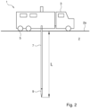
- Fig. 2 shows a schematic side view of an embodiment of a system 1, which can be employed during soil penetration tests for subsurface characterization of a soil 2.
- the system 1 comprises a probe 9 comprising at least a liquid injection port and a pressure transducer.
- the probe 9 is arranged for penetration of the soil 2.
- the system further comprises a data acquisition system arranged for sampling measurement signals from the probe, a controller arranged to control the system to push the probe 9 into the soil 2 and carry out one or more pumping tests, and measure by means of a pressure transducer, for each of the one or more pumping tests, a pressure response in the soil, resulting from the injection of liquid through the liquid injection port.
- the system 1 can comprise a truck 3.
- the truck 3 according to this embodiment has wheels.
- the system 1 may be movable by another transportation unit.
- the truck 3 may further comprise a plurality of stabilizers to provide support and to improve stability during the penetration tests.
- the system 1 can further comprise a rod 7 which is coupled to the probe 9, and means for forcibly penetrating the probe 9 into the soil 2 by pushing the rod 7, wherein a depth of penetration L and a penetration rate of the probe 9 can be controlled by the controller.
- the rod 7 is used to push the probe 9 into the soil, and can include a plurality of sub-elements, such as a plurality of rod sections connected to each other. Other solutions are possible for pushing the probe 9 into the soil.
- the pushing force for penetration of the probe into the soil 2 can be supplied by a hydraulic pushing arrangement, arranged in the truck 3.
- the weight of the truck 3 can provide the reaction force for pushing against the rod 7 which is connected to the probe 9 which is forcibly penetrated into the soil 2.
- Other solutions for providing the reaction force are possible.
- the system comprises a pump arranged to provide liquid, such as water, to the probe, so as to enable the injection of liquid into the soil through the liquid injection port arranged on the probe.
- the system 1 further comprises a digital computer which can be coupled to the probe 9 and its sensors to receive measurement data from the sensors.
- the data acquisition system can be arranged to receive electrical signals from the sensors of the probe 9.
- the digital computer can be coupled to the data acquisition system so as to receive the acquired electrical signals or signals representative for the acquired electrical signals.
- the digital computer can be arranged for processing the electrical signals to provide an analysis of the measurement results so as to determine and/or calculate soil parameters and characteristics.
- the system can comprise an interface, such as a monitor, coupled to the digital computer for displaying a soil analysis which can include the determined soil parameters, such as e.g. permeability and storativity.
- the analysis may be performed for different depths of penetration L.
- the results from a measurement campaign may be combined to provide a general overview of the soil parameters over an area or volume.
- the digital computer can be arranged in a measurement unit in the truck 3 or at a remote unit.
- the measured data may be received by a digital computer through a wired connection or wireless connection.
- a wireless connection device may be arranged to transfer signals through mobile data transfer protocols such as 3G, 4G, 5G, etc.
- mobile data transfer protocols such as 3G, 4G, 5G, etc.
- WiFi e.g., a wireless communication conforming to the IEEE 802.11 standard or other transmission protocol
- LoRa may also be employed to obtain a wireless communication.
- a combination of wireless protocols is possible.
- the system 1 may be implemented in or may take the form of a vehicle.
- the system may be implemented in or take the form of other vehicles, such as cars, recreational vehicles, trucks, agricultural vehicles, construction vehicles and robotic vehicles. It also perceivable that a plurality of systems 1 are included in a vehicle.
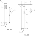
- Fig. 3a and 3b show embodiments of the probe 9 comprising a liquid injection port 11 and a pressure transducer 13.
- Fig. 3a shows a schematic side view of the probe 9 having a substantially elongated tubular shape comprising a tip 17 facing in a longitudinal penetration direction 19 of the probe 9 and arranged for penetrating the soil 2.
- the tip 17 of the tubular probe 9 has a conical shape, however, other shapes are possible.
- the liquid injection port 11 and the pressure transducer 13 of the probe 9 are arranged at a distance D from each other with respect to a longitudinal penetration direction of the probe 9.
- Fig. 3b shows a schematic side view of the probe 9 coupled with rod 7 for being pushed into the soil 2.
- the one or more pumping tests can be conducted, during which the infiltration liquid is pumped through the liquid injection port 11 of the probe 9 in the liquid infiltration flow direction 15 out of the probe 9.
- a pressure response in the soil 2 resulting from the injection of a liquid through the liquid injection port 11 can be measured.
- the one or more pumping tests can be carried out at a predefined/chosen substantially fixed depth of soil penetration L of the probe 9.
- Liquid, such as water can be injected into the soil 2 through the water injection port 11 at a certain water injection flow rate Q which can be adjusted and controlled.
- the one or more pumping tests can be carried out at a substantially constant water injection flow rate Q, while in case of a plurality of pumping tests, successive pumping tests at a certain depth of penetration L can be carried out at different water injection flow rates Q.
- a hydraulic profiling tool, HPT, probe 9 can be used to carry out a cone penetration test, CPT in a hydraulic profiling tool cone penetration test, HPT-CPT.
- the HPT probe 9 is pushed into the ground or soil 2 at a constant rate while water is injected at a constant flow rate into the soil through a water injection port 11 arranged on the HPT probe 9 .
- a HPT-CPT measurement can be used to evaluate hydraulic properties of a site sub-surface.
- the system 1 can comprise a HPT probe 9 comprising a tip or cone equipped with one or more water pressure sensors at a distance D from a HPT probe 9 water injection port 11, i.e. injection point.
- HPT-CPT measurement combines the HPT and the CPT measurement.
- HPT probe movement can be stopped at a certain depth of penetration L. After dissipation of water pressures generated as a result of the HPT measurement, the system 1 can carry out one or more pumping tests wherein water is injected in the soil 2 through the injection port 11.
- the different water injection flow rates can be used to perform a quality assessment of the measurements afterwards by analyzing the pressure response measured by the pressure transducer 13 of the HPT probe 9.
- the water injection flow rate through the water injection port 11 of the HPT probe 9 can induce water overpressures, which may depend on the local geohydrological conditions, and which can be sensed/measured by the pressure transducer 13.
- inverse modelling can be performed on the measured water overpressure.
- the inverse modelling can be performed using analytical solutions or using geohydrogeological numerical modelling.
- the HPT-CPT measurement may be continued after performing one or more pumping tests at a certain depth.
- the probe 9 may e.g.
- the HPT probe 9 may pushed into the soil 2 at the same constant rate while water is injected at the constant flow rate as before the pumping tests. It will be appreciated that the HPT-CPT measurement may be resumed after pore water pressure of the preceding pumping tests has dissipated. It is possible that after the HPT-CPT measurement is resumed after water injection has been restored to the level of the initial HPT-CPT measurement, and water pressure has come to an equilibrium.
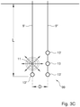
- Fig. 3c shows an embodiment of a probe system 99 comprising a first probe 9' and a second probe 9".'The first and second probes 9', 9" are laterally spaced from each other.
- the first probe 9' comprises the liquid injection port 11.
- the second probe 9" comprises the pressure transducer 13.
- the probe system 99 comprises further pressure transducers 13', 13".
- the liquid injection port 11 and the pressure transducer 13 of the probe system 99 are arranged at a distance D from each other with respect to a lateral direction of the probe 9'.
- the one or more pressure transducers in the 3D space around the injection point can be used to derive horizontal and/or vertical permeability and storativity from the measured pressure response on the injected liquid Q.
- the pressure transducer 13 can be used to determine the horizontal permeability and storativity.
- the pressure transducer 13" can be used to determine the vertical permeability and storativity.
- the horizontal and/or vertical permeability and storativity can be derived using numerical or analytical calculations with an inverse modelling technique.
- Fig. 4 shows a graph, illustrating pore water pressure characteristics during pumping tests.
- the probe 9 including a liquid injection port 11 and a pressure transducer 13 is pushed into a soil 2 at a certain depth of penetration L, where, in this example, three consecutive pumping tests are carried out without waiting time between the three pumping tests. This is also referred to as steptest. Similar pumping tests can be carried out at different penetration locations and/or depths of penetration L.
- a pumping test infiltration liquid such as water
- the pressure transducer 13 a pressure response in the soil 2 resulting from the injection of water through the liquid injection port 11 is measured for three different injection flow rate pumping test.
- the pore water pressure is plotted in function of time for the successive pumping tests.
- water injection through the liquid injection port 11 is stopped.
- time t1 indicated by line 21
- the first pumping test with injection rate Q1 of the three pumping tests is initiated.
- water is injected and pumped through the injection port 11 of the probe 9 at a first liquid injection flow rate Q1.
- the liquid injection flow rate Q is kept constant and the pore water pressure has substantially converged to a steady state value at time t2.
- the first pumping test is finalized and the second pumping test is started, indicated by line 23.
- the second pumping test water is injected and pumped through the injection port 11 of the probe 9 at a second liquid injection flow rate Q2, different from the first injection flow rate of the first pumping test Q1.
- the second liquid injection flow rate Q2 is higher than the first liquid injection flow rate Q1, which causes the pore water pressure to substantially converge to a second value higher than the first converged value of the pore water pressure in the first pumping test.
- a third pumping test is initiated at time t3, indicated by line 25, wherein again the liquid injection flow rate is increased with respect to the previous pumping test, i.e. the second pumping test.
- the pore water pressure during the third pumping test converges again to a certain value.
- the third pumping test is finalized at time t4, indicated by line 27.
- a steptest including three pumping tests are illustrated in this example, it is also possible to carry out a steptest including another number of pumping tests, for example one pumping test. Other quantities such as two, four, five, ten, twelve, twenty, etc. pumping tests can be carried out. It is also possible that a single pumping test is performed at the penetration location. It is also possible that a plurality of pumping tests is carried out with waiting times in between the pumping tests at the penetration location. During the waiting time liquid injection may be halted or the liquid injection rate set at a reference level.
- the three pumping tests in this example can also be considered as a series of one or more pumping tests, wherein such series of pumping tests can be carried out at different penetration locations and/or depths of penetration L.
- the series of pumping tests can be different with respect to each other, e.g. may comprise a different number of pumping tests, different liquid injection flow rates Q, etcetera.
- Fig. 5 shows a graph, illustrating pore water pressure characteristics during pumping tests.
- the probe 9 including a liquid injection port 11 and a pressure transducer 13 is pushed into a soil 2 at a certain depth of penetration L, where, in this example, three pumping tests are carried out.
- a pumping test infiltration liquid such as water
- the pressure transducer 13 a pressure response in the soil 2 resulting from the injection of water through the liquid injection port 11 is measured for each of the three pumping tests.
- the pore water pressure is plotted in function of time for successive pumping tests and dissipation tests.
- a dissipation test is carried out, wherein pumping of infiltration liquid (water) through the liquid injection port 11 of the probe 9 with Q0 is stopped after the stopping the HPT at a certain depth in order to obtain a substantially hydrostatic pressure state.
- a dissipation test is initiated.
- a substantially hydrostatic pressure state is obtained, after which, at time t11, indicated by line 31, the first pumping test of the three pumping tests can be initiated.
- water is injected and pumped through the liquid injection port 11 of the probe 9 at a first liquid injection flow rate Q1, for example at 1 liter/minute.
- the liquid injection flow rate Q1 is kept constant and as a result the pore water pressure has substantially converged to a certain steady state value at time t12.
- t12 indicated by line 33
- the first pumping test is finished and the second pumping test is started.
- water is injected and pumped through the injection port 11 of the probe 9 at a second liquid injection flow rate Q2, different from the first injection flow rate Q1 during the first pumping test, for example 2 liter/minute.
- the second injection liquid injection flow rate Q2 is higher than the first liquid injection flow rate Q1, which causes the pore water pressure to substantially converge to a second steady state value wherein the converged value is higher than the converged value of the pore water pressure as a result of the first pumping test.
- a third pumping test is initiated at time t13, indicated by line 35, wherein again the liquid injection flow rate is increased with respect to the previous pumping test, i.e. the second pumping test, for example from 2 liter/minute to 3 liter/minute.
- the pore water pressure during the third pumping test converges again to a certain value.
- the third pumping test is finalized at time t14, indicated by line 37.
- the third pumping test is followed by another dissipation test, at time 14, wherein pumping of infiltration liquid through the liquid injection port 11 of the probe 9 is stopped in order to obtain a substantially hydrostatic pressure state.
- This dissipation test is finalized at time t15.
- the individual pumping tests take approximately 5 minutes. However, other durations are possible and can be dependent on the hydrogeological properties of the soil.
- three pumping tests are illustrated in this example, another number of pumping tests can be carried out.
- multiple series of one or more pumping tests can be carried out by the system 1.
- the series of one or more pumping tests can be different with respect to each other, e.g. may comprise a different number of pumping tests, different liquid injection flow rates Q, etcetera.
- the probe may be advanced to a next penetration depth. During advancement a HPT or HPT-CPT measurement may be carried out.
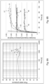
- Fig. 6a illustrates a graph, illustrating pore water pressure characteristics.
- the measured pore water pressure (no correction) is plotted in function of a logarithmic time scale.
- the pore water pressure during three pumping tests 41 , 43, 45 is shown in function of time.
- a dissipation test is carried out prior to the first pumping test 41 to obtain a substantially hydrostatic state.
- the water injection flow rate Q is increased step wise, resulting in a step wise increase at the pore water pressure.
- a dissipation test is carried out, resulting in a drop in the measured pore water pressure.
- Fig. 6b shows a graph, illustrating the increase in measured pressure head as a result of the pumping tests according to the example shown in Fig. 6a .
- the increase in measured pressure head 47 can be fitted on a model calculated curve 53.
- the increase in measured pressure head 49 and 51 can be fitted on model calculated curves 55 and 57, respectively.
- the model curves 53, 55, 57 can for instance be used to determine steady state convergence values and for deriving soil properties, such as permeability and storativity.
- the increase in pore water pressure caused by injecting liquid into the soil can be a measure for the permeability of the encountered soil layers.
- the ratio between the injection flow rate and pressure Q/P can give the hydraulic index or relative permeability.
- the measured pore water pressure is the sum of the hydrostatic pore water pressure, the pore water pressure buildup due to injection and air pressure.
- the hydrostatic pressure can be determined by dissipation tests.
- the parameters hydraulic conductivity K and storage coefficient Ss can be determined for each pumping test by fitting a model on the measured pore water pressure increase, e.g. by the use of a model with a transient groundwater flow equation.
- This equation describes a positive linear relationship between Q/P and K and approaches the origin if K approaches 0.
- the constant 1/C can be determined by using the determined permeability values and corresponding Q/P values from the one or more pumping tests.
- the relationship between conductivity K and Q/P can be plotted in a graph. A trend line going through the origin is then plotted for the data, wherein the slope of the trend line can indicate the constant 1/C.
- the determined K value gives a measure of the permeability and storativity of the layer between the infiltration point, i.e. liquid injection port, and conus tip.
- the increase in pressure at a given injection flow rate depends on the permeability of the soil and the distance of the point of measurement to the injection point/port.
- the rate at which the pressure increase becomes constant after a change in flow rate i.e. the duration of the transient phase/lag time
- Permeability is important for groundwater flow calculations, wherein groundwater flow rate plays a role.
- Storativity is important to carry out time-dependent groundwater flow calculations.
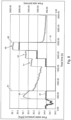
- Fig. 7 shows a graph, illustrating measured pressure head (first x-axis) and liquid injection flow rate Q (second x-axis) as a function of time.
- Curve 59 indicates the pressure head and curve 61 indicates the liquid injection flow rate Q through the liquid injection port 11 in the probe 9.
- the liquid injection flow rate Q is initially zero prior to starting three pumping tests 41, 43 and 45. This can for instance be a result of a dissipation test, wherein pumping of infiltration liquid through the liquid injection port 11 of the probe 9 is stopped in order to obtain a substantially hydrostatic pressure state.
- a substantially hydrostatic pressure state prior to starting pumping tests can be advantageous.
- Line 63 indicates the start at time t20 of the first pumping test 41, wherein infiltration liquid is pumped through the liquid injection port 11 of the probe 9 and injected into the soil 2 at a constant liquid injection flow rate Q, of approximately 1 liter/minute in this example.
- the pressure head substantially converges to a steady state value.
- the measurement of the first pumping test 41 is ended at time t21, indicated by line 65.
- the liquid injection flow rate Q during the first pumping test 41 is maintained until the second pumping test 43 is started at time t22, indicated by line 67.
- the liquid injection flow rate Q through the liquid injection port 11 of the probe 9 is increased to approximately 2 liter/minute in this example.
- the measured pressure head converges to a new steady state value.
- the measurement of the second pumping test 43 is ended at time t23, indicated by line 69.
- the liquid injection flow rate Q during the second pumping test 43 is maintained until the third pumping test 45 is started at time t24 indicated by line 71.
- the liquid injection flow rate Q is again increased, to approximately 3 liter/minute in this example.
- the measured pressure head converges to a new higher steady state value.
- the measurement of the third pumping test 45 is ended at time t25, indicated by line 73.
- liquid injection flow rate Q during the third pumping test 45 is maintained in this example until time t26, indicated by line 75, at which liquid injection through the liquid injection port 11 of the probe 9 is stopped, causing a drop of the measured pressure head.
- a dissipation test can be carried out, wherein pumping of infiltration liquid through the liquid injection port 11 of the probe 9 is stopped in order to obtain a substantially hydrostatic pressure state.
- Fig. 8 shows an exemplary graph illustrating measured pore water pressure and flow rate during different pumping tests.
- the example show three successive pumping tests 41, 43 and 45 carried out at different water injection flow rates Q, namely 0.5 liter/minute, 1 liter/minute and 2 liter/minute, respectively.
- a steptest including three pumping tests 41, 43 and 45 is illustrated, another number of pumping tests is possible. Any combination of pumping tests, e.g. in series, with or without intermediate periods of rest, at stepped flow rates or otherwise, can be performed. For instance, in another exemplary embodiment, only one pumping test can be carried out. It is also possible that one or more pumping tests are carried out at different depths of penetration L of the probe 9 into the soil 2.
- Curve 60 indicates the measured pore water pressure at measurement point 13 and curve 61 indicates the liquid injection flow rate Q at the injection port 11.
- the liquid injection flow rate Q0 used during the HPT measurement is stopped prior at line 81 to starting the series of pumping tests 41, 43, 45.
- the resulting pore pressure decrease corresponds to a dissipation test, which will eventually reach a substantially hydrostatic pressure state.
- Another dissipation test is carried out after the last pumping test of three pumping tests has ended at line 83 .
- a HPT probe 9 is arranged to evaluate hydraulic properties of the site subsurface. While the HPT probe 9 is advanced through the soil 2, liquid or water can be injected at a constant liquid injection flow rate Q through a water/liquid injection port 11 on a side of the HPT probe 9.
- An in-line pressure sensor can measure the response pressure of the soil/groundwater system against water injection by the HPT probe 9 through the water injection port 11. The water flows into the soil layers at a certain rate and with a certain pressure build up depending on the hydraulic properties of the soil 2. For instance, a low response pressure can indicate a large grain size, and the ability to easily transmit water. A high response pressure, however, can indicate a small grain size and the inability to transmit water.
- Pressure and water injection flow rate can both be logged versus depth.
- the HPT probe 9 movement can be stopped, followed by one or more pumping tests, wherein water is injected into the soil 2 at the depth of penetration L by the HPT probe 9 through the water injection port 11 of the HPT probe 9.
- the resulting water pressure is measured by the pressure transducer 13 of the HPT probe 9.
- the HPT probing can then, if necessary, be continued and pushed further to a next depth of penetration L where one or more pumping tests are going to be conducted.
- the HPT probe 9 movement can be stopped as well as the HPT injection, followed by a dissipation test so as to allow dissipation of HPT generated pressures in the soil 2.
- a dissipation test so as to allow dissipation of HPT generated pressures in the soil 2.
- one or more pumping tests can be conducted at a substantially fixed depth of penetration, where water is injected into the soil 2 by the HPT probe 9 through the water injection port 11 at a substantially constant water injection flow rate Q.
- the water injection flow rate Q for the different pumping tests can be different.
- the resulting water pressure is measured by the pressure transducer 13 of the HPT probe 9.
- the one or more pumping tests can be followed by a dissipation test for dissipation of the generated overpressures by the one or more pumping tests.
- the HPT probing can then be continued to a next depth of penetration L where one or more pumping tests are going to be conducted.
- Inverse modelling can be employed on generated waterpressures resulting in permeability (K) and storativity (Ss).
- the HPT relative permeability (Q/P) profile can be converted to an absolute profile using linear correlation with HPT data.
- the probe 9 can comprise a plurality of additional sensors for measuring the soil parameters.
- a plurality of sensors can be arranged to generate electrical signals representative of the measured values.
- a multi-parameter probe can be employed for providing a tool which allows acquisition of several parameters with just one push.
- the acquisition of one or more of the parameters can be on-the-fly or real-time. Since the measurements can be conducted simultaneously in one push, it is not necessary to carry out multiple measurements. In this way, a cost-effective method for subsurface investigation can be obtained.
- typically a plurality of separate pushes were necessary to acquire the same amount and volume of data, usually by use of multiple separate probes.
- Other sensors can be included in the probe 9 to allow e.g. an improved understanding of the spatial distribution of contaminants when investigating the soil 2 using the probe 9, which can deliver the basis for a reliable risk assessment and remediation planning of subsurface contamination.
- a MIP-HPT-CPT Membrane Interface Probe - Hydraulic Profiling Tool - Cone Penetration Test
- the probe 9 can therefore be also used to identify potential contaminant migration pathways. Similarly, it can help to identify zones for remedial material injection or provide qualitative guidance on how difficult injection may be in different zones of the formation. Further, hydraulic conductivities as well as mass flow rates can be obtained by a combined processing of the acquired datasets.
- strain gauge load cells can be arranged on the probe for measuring forces resisting tip penetration, lateral forces resisting penetration.
- the method for determining soil parameters comprising penetrating a hydraulic profiling tool (HPT) probe into a soil; carrying out a plurality of pumping tests wherein infiltration liquid is pumped into the soil from an injection port of the HPT probe at different, substantially constant, liquid injection flow rates Q; measuring, for each of the plurality of MPTs, starting from a substantially hydrostatic state, a pressure response in the soil by a pressure transducer arranged at a portion of the HPT probe, the pressure response resulting from the injection of liquid through the injection port of the HPT probe.
- HPT hydraulic profiling tool
- the present invention can be carried out by modifying existing probes, such as HTP, CPT, and/or MIP probes, which are pushed into the subsurface soil to obtain data. Additionally or alternatively, the probe 9 can be detachably arranged and/or interchangeable.
- data acquired in the field is transferred online (e.g. wireless) and is processed by a user using one or more software packages.
- the probe comprises a plurality of sensors
- data coming from the different sensors can be processed by different software packages or a same software package.
- Software packages can further be arranged to communicate and work together.
- processed data can be displayed (e.g. 2D, 3D, quasi-3D, etc. visualization) using a visualization software package.
- Datasets can be visualized as 3D-blockdiagrams, 3D-stacked isomaps, cross-sections, maps of maximum signals, etc. Other visualizations are possible.
- the depth of penetration L can be seen as the penetrated distance of the probe 9 through the soil surface 2a into the soil 2.
- the probe 9 has penetrated the soil 2 substantially perpendicular with respect to the ground or soil surface.
- other types of penetrations are possible.
- Embodiments may comprise computer apparatus, wherein processes are performed in a computer apparatus.
- the invention also extends to computer programs, particularly computer programs on or in a carrier, adapted for putting the invention into practice.
- the program may be in the form of source or object code or in any other form suitable for use in the implementation of the processes according to the invention.
- the carrier may be any entity or device capable of carrying the program.
- the carrier may comprise a storage medium, such as a ROM, for example a CD ROM or a semiconductor ROM, or a magnetic recording medium, for example a floppy disc, USB memory or hard disk.
- the carrier may be a transmissible carrier such as an electrical or optical signal which may be conveyed via electrical or optical cable or by radio or other means, e.g. via the internet or cloud.
- Some embodiments may be implemented, for example, using a machine or tangible computer-readable medium or article which may store an instruction or a set of instructions that, if executed by a machine, may cause the machine to perform a method and/or operations in accordance with the embodiments.
- a machine may include, for example, any suitable processing platform, computing platform, computing device, processing device, computing system, processing system, computer, processor, or the like, and may be implemented using any suitable combination of hardware and/or software.
- the machine-readable medium or article may include, for example, any suitable type of memory unit, memory device, memory article, memory medium, storage device, storage article, storage medium and/or storage unit, for example, memory, removable or non-removable media, erasable or non-erasable media, writeable or re-writeable media, digital or analog media, hard disk drive, floppy disk, Compact Disk Read Only Memory (CD-ROM), Compact Disk Recordable (CD-R), Compact Disk Rewriteable (CD-RW), optical disk, magnetic media, magneto-optical media, removable memory cards or disks, various types of Digital Versatile Disk (DVD), a tape, a cassette, or the like.
- any suitable type of memory unit for example, any suitable type of memory unit, memory device, memory article, memory medium, storage device, storage article, storage medium and/or storage unit, for example, memory, removable or non-removable media, erasable or non-erasable media, writeable or re-writeable media, digital or analog media, hard
- the instructions may include any suitable type of code, such as source code, compiled code, interpreted code, executable code, static code, dynamic code, encrypted code, and the like, implemented using any suitable high-level, low-level, object-oriented, visual, compiled and/or interpreted programming language.
- the digital computer and/or the controller of the system 1 can communicate using wireless systems, wired systems, or a combination of both.
- the system may include components and interfaces suitable for communicating or wired communications media, such as input/output (I/O) adapters, physical connectors to connect the I/O adapter with a corresponding wired communications medium.
- I/O input/output
- the system may include components and interfaces suitable for communicating over a wireless shared media, such as one or more antennas, transmitters, receivers, transceivers, amplifiers, filters, control logic, and so forth.
- An example of wireless shared media may include portions of a wireless spectrum, such as the RF spectrum and so forth.
- a wireless communication device may be included in order to transmit and receive signals using various suitable wireless communications techniques. Such techniques may involve communications across one or more wireless networks. Exemplary wireless networks include, but are not limited to, cellular networks, wireless local area networks (WLANs, cfr. WiFi), wireless personal area networks (WPANs), wireless metropolitan area network (WMANs), satellite networks, et cetera. In communicating across such networks, the transmitter may operate in accordance with one or more applicable standards in any version.
- WLANs wireless local area networks
- WPANs wireless personal area networks
- WMANs wireless metropolitan area network
- satellite networks et cetera
- any reference signs placed between parentheses shall not be construed as limiting the claim.
- the word 'comprising' does not exclude the presence of other features or steps than those listed in a claim.
- the words 'a' and 'an' shall not be construed as limited to 'only one', but instead are used to mean 'at least one', and do not exclude a plurality.
- the mere fact that certain measures are recited in mutually different claims does not indicate that a combination of these measures cannot be used to an advantage.
Landscapes
- Life Sciences & Earth Sciences (AREA)
- Engineering & Computer Science (AREA)
- Mining & Mineral Resources (AREA)
- Chemical & Material Sciences (AREA)
- Analytical Chemistry (AREA)
- General Life Sciences & Earth Sciences (AREA)
- Physics & Mathematics (AREA)
- Geology (AREA)
- Fluid Mechanics (AREA)
- Soil Sciences (AREA)
- Structural Engineering (AREA)
- General Engineering & Computer Science (AREA)
- Civil Engineering (AREA)
- Paleontology (AREA)
- Environmental & Geological Engineering (AREA)
- Geochemistry & Mineralogy (AREA)
- Biochemistry (AREA)
- Pathology (AREA)
- Immunology (AREA)
- General Physics & Mathematics (AREA)
- General Health & Medical Sciences (AREA)
- Health & Medical Sciences (AREA)
- Dispersion Chemistry (AREA)
- Hydrology & Water Resources (AREA)
- Investigation Of Foundation Soil And Reinforcement Of Foundation Soil By Compacting Or Drainage (AREA)
Claims (14)
- System zur Bestimmung von Bodeneigenschaften, umfassend:
ein Sondensystem (99), das zum Durchdringen eines Bodens eingerichtet ist, wobei das Sondensystem Folgendes umfasst:eine erste Sonde (9') mit wenigstens einer Flüssigkeitsinjektionsöffnung (11) und wenigstens einem ersten Druckmessumformer (13"); undeine zweite Sonde (9") mit wenigstens einem zweiten Druckmessumformer (13, 13'), wobei der erste und zweite Druckmessumformer dazu eingerichtet sind, in einem 3D-Raum (X, Y, Z) rund um einen Injektionspunkt verwendet zu werden;eine Steuerung, die dazu eingerichtet ist, das System zu Folgendem zu steuern:Hineindrücken des Sondensystems in den Boden;Ausführen eines oder mehrerer Pumpversuche, wobei während eines Pumpversuchs Infiltrationsflüssigkeit durch die Injektionsöffnung gepumpt wird; undMessen - mittels des ersten und zweiten Druckmessumformers, für jeden des einen oder der mehreren Pumpversuche - von Druckreaktionen in dem Boden infolge der Injektion von Flüssigkeit durch die Flüssigkeitsinjektionsöffnung; undwobei das System ferner ein Datenerfassungssystem umfasst, das zum Abgreifen von Messsignalen in Form von elektrischen Signalen von dem ersten und zweiten Druckmessumformer eingerichtet ist. - System nach Anspruch 1, wobei die erste und zweite Sonde dazu ausgestaltet sind, derart in den Boden hineingedrückt zu werden, dass die Flüssigkeitsinjektionsöffnung und der zweite Druckmessumformer in Bezug auf eine seitliche Richtung der ersten Sonde in einem Abstand D voneinander angeordnet sind.
- System nach Anspruch 2, das ferner einen Digitalrechner umfasst, der dazu eingerichtet ist, die elektrischen Signale von dem Datenerfassungssystem zu empfangen und zu verarbeiten, um eine Analyse der Messsignale bereitzustellen, wobei der Digitalrechner ferner dazu eingerichtet ist, von der unter Verwendung des ersten und zweiten Druckmessumformers gemessenen Reaktion auf die Flüssigkeitsinjektion die horizontale und/oder vertikale absolute Permeabilität und den Speicherkoeffizienten abzuleiten,
wobei die absolute Permeabilität von einem Profil der relativen Permeabilität abgeleitet wird, und zwar mittels linearer Korrelation mit den Messsignalen, wobei die relative Permeabilität auf einem Verhältnis zwischen der Injektionsdurchflussrate und dem durch die Flüssigkeitsinjektion bedingten Druck basiert. - System nach Anspruch 3, wobei der eine oder die mehreren Pumpversuche in unterschiedlichen Tiefen durchgeführt werden, wobei die Pumpversuche aus einer Kombination von HPT (Hydraulic Profiling Tool) und MPT (Mini-Pumping Test) bestehen;
und wobei der Digitalrechner ferner dazu eingerichtet ist, eine dreidimensionale oder quasi-dreidimensionale Darstellung der absoluten Permeabilität und/oder des Speicherkoeffizienten des Bodens zu erhalten. - Verfahren zur Bestimmung von Bodeneigenschaften, umfassend:a. Hineindrücken eines Sondensystems in einen Boden, wobei das Sondensystem Folgendes umfasst:eine erste Sonde mit wenigstens einer Flüssigkeitsinjektionsöffnung und wenigstens einem ersten Druckmessumformer undeine zweite Sonde mit wenigstens einem zweiten Druckmessumformer, wobei der erste und zweite Druckmessumformer in einem 3D-Raum (X, Y, Z) rund um einen Injektionspunkt verwendet werden;b. Ausführen eines oder mehrerer Pumpversuche, wobei während eines Pumpversuchs Infiltrationsflüssigkeit durch die Flüssigkeitsinjektionsöffnung in den Boden gepumpt wird; undc. Messen - mittels des ersten und zweiten Druckmessumformers, für jeden des einen oder der mehreren Pumpversuche - einer Druckreaktion in dem Boden infolge der Injektion von Flüssigkeit durch die Flüssigkeitsinjektionsöffnung.
- Verfahren nach Anspruch 5, wobei das Verfahren im Zuge einer Drucksondierung ausgeführt wird, bei der die erste und zweite Sonde mit einer kontrollierten Eindringgeschwindigkeit in den Boden hineingedrückt werden, während Infiltrationsflüssigkeit durch die Injektionsöffnung in den Boden injiziert wird, und wobei ein oder mehrere Pumpversuche ausgeführt werden, bei denen die erste und zweite Sonde im Wesentlichen stationär in Bezug auf den Boden in einer oder mehreren festgelegten Eindringtiefen befindlich sind,
wobei durch Vornehmen der Drucksondierung eine Hydraulic-Profiling-Drucksondierung (hydraulic profiling cone penetration test, HPT-CPT) durchgeführt wird, wobei das Sondensystem als Hydraulic Profiling Tool verwendet wird. - Verfahren nach Anspruch 6, wobei die erste und zweite Sonde in festgelegten Eindringtiefen angehalten werden, um den einen oder die mehreren Pumpversuche durchzuführen;
wobei vorzugsweise die Injektion von Infiltrationsflüssigkeit gestoppt wird, wenn die Sonden in den festgelegten Tiefen angehalten werden, und der eine oder die mehreren Pumpversuche nach der Dissipation des durch das HPT erzeugten Porenwasserdrucks durchgeführt werden. - Verfahren nach Anspruch 6, wobei die HPT-CPT nach dem Ausführen des einen oder der mehreren Pumpversuche in den festgelegten Eindringtiefen mit der kontrollierten Eindringgeschwindigkeit wiederaufgenommen wird.
- Verfahren nach einem der Ansprüche 5 bis 8, das ein Ableiten der horizontalen und/oder vertikalen absoluten Permeabilität und des Speicherkoeffizienten von der unter Verwendung des ersten und zweiten Druckmessumformers in dem 3D-Raum (X, Y, Z) rund um die Injektionsöffnung gemessenen Reaktion auf die Flüssigkeitsinjektion umfasst,wobei die erste und zweite Sonde derart in den Boden hineingedrückt werden, dass die Flüssigkeitsinjektionsöffnung und der zweite Druckmessumformer in Bezug auf eine seitliche Richtung der ersten Sonde in einem Abstand D voneinander angeordnet sind;und vorzugsweise ferner einen oder mehrere der folgenden Schritte umfasst:Bestimmen der horizontalen und/oder vertikalen absoluten Permeabilität und des Speicherkoeffizienten,wobei die Permeabilität basierend auf einem Profil der relativen Permeabilität bestimmt wird, und zwar mittels linearer Korrelation mit den Messsignalen, wobei die relative Permeabilität auf einem Verhältnis zwischen der Injektionsdurchflussrate und dem durch die Flüssigkeitsinjektion bedingten Druck basiert.
- Verfahren nach einem der Ansprüche 5 bis 9, wobei der eine oder die mehreren Pumpversuche in einer im Wesentlichen feststehenden Bodeneindringtiefe der ersten Sonde ausgeführt werden.
- Verfahren nach einem der Ansprüche 5 bis 10, wobei die erste und zweite Sonde in den Boden hineingedrückt werden, bis eine festgelegte Eindringtiefe der ersten und zweiten Sonde erreicht ist.
- Verfahren nach einem der Ansprüche 5 bis 11, wobei der eine oder die mehreren Pumpversuche in einer Mehrzahl von Eindringtiefen vorgenommen werden.
- Verfahren nach einem der Ansprüche 5 bis 12, wobei der eine oder die mehreren Pumpversuche eine Mehrzahl von Pumpversuchen umfassen und wobei ein nachfolgender Pumpversuch mit einer anderen Flüssigkeitsinjektionsdurchflussrate Q ausgeführt wird, wenn die Druckreaktion während eines vorherigen Pumpversuchs sich auf einen im Wesentlichen konstanten Wert eingepegelt hat.
- Computerprogrammprodukt zur Bestimmung von Bodeneigenschaften unter Verwendung eines Sondensystems (99), das eine erste Sonde (9') mit wenigstens einer Flüssigkeitsinjektionsöffnung (11) und wenigstens einem ersten Druckmessumformer (13") und eine zweite Sonde (9") mit wenigstens einem zweiten Druckmessumformer (13, 13') umfasst, wobei der erste und zweite Druckmessumformer dazu eingerichtet sind, in einem 3D-Raum (X, Y, Z) rund um einen Injektionspunkt verwendet zu werden, wobei das Computerprogrammprodukt Anweisungen umfasst, um zu bewirken, dass ein Prozessor folgende Schritte durchführt:Bereitstellen eines ersten Signals zum Ausführen eines oder mehrerer Pumpversuche, wobei während eines Pumpversuchs Infiltrationsflüssigkeit durch die Flüssigkeitsinjektionsöffnung (11) des Sondensystems (99) gepumpt wird;Bereitstellen eines zweiten Signals zum Messen - mittels des ersten und zweiten Druckmessumformers (13", 13, 13'), für jeden des einen oder der mehreren Pumpversuche - einer Druckreaktion in dem Boden infolge der Injektion von Flüssigkeit durch die Flüssigkeitsinjektionsöffnung;Empfangen von Messdaten für jeden des einen oder der mehreren Pumpversuche; undBestimmen - anhand der Messdaten des einen oder der mehreren Pumpversuche - von für Bodeneigenschaften repräsentativen Informationen;wobei vorzugsweise die für Bodeneigenschaften repräsentativen Informationen die horizontale und/oder vertikale absolute Permeabilität und den Speicherkoeffizienten umfassen.
Applications Claiming Priority (3)
| Application Number | Priority Date | Filing Date | Title |
|---|---|---|---|
| NL2017006A NL2017006B1 (en) | 2016-06-20 | 2016-06-20 | a method, a system, and a computer program product for determining soil properties |
| PCT/NL2017/050410 WO2017222372A1 (en) | 2016-06-20 | 2017-06-20 | A method, a system, and a computer program product for determining soil properties |
| EP17737896.5A EP3472392B1 (de) | 2016-06-20 | 2017-06-20 | Verfahren, system und computerprogrammprodukt zur bestimmung von bodeneigenschaften |
Related Parent Applications (1)
| Application Number | Title | Priority Date | Filing Date |
|---|---|---|---|
| EP17737896.5A Division EP3472392B1 (de) | 2016-06-20 | 2017-06-20 | Verfahren, system und computerprogrammprodukt zur bestimmung von bodeneigenschaften |
Publications (2)
| Publication Number | Publication Date |
|---|---|
| EP3936669A1 EP3936669A1 (de) | 2022-01-12 |
| EP3936669B1 true EP3936669B1 (de) | 2023-08-02 |
Family
ID=57104120
Family Applications (2)
| Application Number | Title | Priority Date | Filing Date |
|---|---|---|---|
| EP17737896.5A Active EP3472392B1 (de) | 2016-06-20 | 2017-06-20 | Verfahren, system und computerprogrammprodukt zur bestimmung von bodeneigenschaften |
| EP21193959.0A Active EP3936669B1 (de) | 2016-06-20 | 2017-06-20 | Verfahren, system und computerprogrammprodukt zur bestimmung von bodeneigenschaften |
Family Applications Before (1)
| Application Number | Title | Priority Date | Filing Date |
|---|---|---|---|
| EP17737896.5A Active EP3472392B1 (de) | 2016-06-20 | 2017-06-20 | Verfahren, system und computerprogrammprodukt zur bestimmung von bodeneigenschaften |
Country Status (6)
| Country | Link |
|---|---|
| US (2) | US11320358B2 (de) |
| EP (2) | EP3472392B1 (de) |
| CA (1) | CA3027841A1 (de) |
| DK (2) | DK3472392T3 (de) |
| NL (1) | NL2017006B1 (de) |
| WO (1) | WO2017222372A1 (de) |
Families Citing this family (14)
| Publication number | Priority date | Publication date | Assignee | Title |
|---|---|---|---|---|
| NL2017006B1 (en) | 2016-06-20 | 2018-01-04 | Fugro N V | a method, a system, and a computer program product for determining soil properties |
| RU186588U1 (ru) * | 2018-09-20 | 2019-01-24 | Федеральное государственное казенное военное образовательное учреждение высшего образования "ВОЕННАЯ АКАДЕМИЯ МАТЕРИАЛЬНО-ТЕХНИЧЕСКОГО ОБЕСПЕЧЕНИЯ имени генерала армии А.В. Хрулева" | Плашкоут установки статического зондирования грунтов |
| CN109975336A (zh) * | 2019-04-23 | 2019-07-05 | 西南石油大学 | 一种基于ct扫描的裂缝性岩心窜流系数测量方法 |
| CN110365356A (zh) * | 2019-06-20 | 2019-10-22 | 东南大学 | 可实现孔压静力触探测试数据无线传输的装置 |
| US11624850B2 (en) | 2019-10-29 | 2023-04-11 | Pgs Geophysical As | Marine survey node and soil sample module |
| CN111323560A (zh) * | 2020-03-30 | 2020-06-23 | 山东省环境保护科学研究设计院有限公司 | 一种车载式多功能钻机与静力触探一体化平台 |
| JP7415858B2 (ja) * | 2020-09-10 | 2024-01-17 | 栗田工業株式会社 | 土壌又は地下水中の揮発性有機化合物の測定方法 |
| JP7788304B2 (ja) * | 2022-02-25 | 2025-12-18 | 大成建設株式会社 | 針貫入試験装置 |
| NL2032573B1 (en) | 2022-07-22 | 2024-01-29 | Fnv Ip Bv | Infiltration point detection |
| US20260043314A1 (en) * | 2023-01-17 | 2026-02-12 | Schlumberger Technology Corporation | Volumetric geometry quantification of near-surface carbon containers |
| CN116911070B (zh) * | 2023-09-07 | 2024-01-26 | 长江三峡集团实业发展(北京)有限公司 | 一种土基材料蓄水能力评估方法、装置、设备及存储介质 |
| CN117074180B (zh) * | 2023-10-17 | 2023-12-12 | 天津风霖物联网科技有限公司 | 一种建筑物地下土体压力变化测量方法 |
| NL2037121B1 (en) * | 2024-02-26 | 2025-09-04 | Fnv Ip Bv | A hydraulic profiling tool probe |
| CN119843629B (zh) * | 2025-03-07 | 2025-10-31 | 天津大学 | 同时取样及测定软黏土灵敏度的静力触探试验装置及方法 |
Family Cites Families (84)
| Publication number | Priority date | Publication date | Assignee | Title |
|---|---|---|---|---|
| US4192182A (en) * | 1978-11-16 | 1980-03-11 | Sylvester G Clay | Method for performing step rate tests on injection wells |
| US4228855A (en) * | 1979-06-22 | 1980-10-21 | Texaco Inc. | Method of injectivity profile logging for two phase flow |
| US4352780A (en) * | 1979-07-13 | 1982-10-05 | Fiatron Systems, Inc. | Device for controlled injection of fluids |
| US4353249A (en) * | 1980-10-30 | 1982-10-12 | Systems, Science And Software | Method and apparatus for in situ determination of permeability and porosity |
| US4420975A (en) * | 1981-06-30 | 1983-12-20 | Marathon Oil Company | System and method for determining the relative permeability of an earth formation surrounding a wellbore |
| US4400970A (en) * | 1981-09-24 | 1983-08-30 | Ali Muhammad A | Method of and apparatus for measuring in situ, the sub-surface bearing strength, the skin friction, and other sub-surface characteristics of the soil |
| US4492111A (en) * | 1981-10-07 | 1985-01-08 | Kirkland James L | Rheological penetrometer |
| US4453401A (en) * | 1982-03-12 | 1984-06-12 | The United States Of America As Represented By The Secretary Of The Air Force | Pressure sensor and soil stress isolation filter arrangement in a pore pressure probe |
| US4554819A (en) * | 1983-09-28 | 1985-11-26 | Ali Muhammad A | Method of and apparatus for measuring in situ, the subsurface bearing strength, the skin friction, and other subsurface characteristics of the soil |
| US4523459A (en) * | 1984-03-09 | 1985-06-18 | Atlantic Richfield Company | Method for performing step rate tests on injection wells |
| US4799157A (en) * | 1984-09-07 | 1989-01-17 | Schlumberger Technology Corporation | Method for uniquely estimating permeability and skin factor for at least two layers of a reservoir |
| US4742459A (en) * | 1986-09-29 | 1988-05-03 | Schlumber Technology Corp. | Method and apparatus for determining hydraulic properties of formations surrounding a borehole |
| US4856318A (en) * | 1987-07-20 | 1989-08-15 | Playground Clearing House, Inc. | Surface resiliency tester |
| US4807707A (en) * | 1987-10-26 | 1989-02-28 | Handley James P | Sampling apparatus and method |
| US4936139A (en) * | 1988-09-23 | 1990-06-26 | Schlumberger Technology Corporation | Down hole method for determination of formation properties |
| US4860581A (en) * | 1988-09-23 | 1989-08-29 | Schlumberger Technology Corporation | Down hole tool for determination of formation properties |
| US5042595A (en) * | 1990-02-05 | 1991-08-27 | La Corporation De L'ecole Polytechnique | Method and device for in-situ determination of rheological properties of earth materials |
| US5168765A (en) * | 1991-01-23 | 1992-12-08 | Broussard Patrick M | Water sampler |
| US5335542A (en) * | 1991-09-17 | 1994-08-09 | Schlumberger Technology Corporation | Integrated permeability measurement and resistivity imaging tool |
| US5219388A (en) * | 1992-01-17 | 1993-06-15 | University Of Florida | Method and apparatus for testing water permeability of concrete |
| US5246862A (en) * | 1993-03-24 | 1993-09-21 | The United States Of America As Represented By The Secretary Of The Army | Method and apparatus for in-situ detection and determination of soil contaminants |
| US5520248A (en) * | 1995-01-04 | 1996-05-28 | Lockhead Idaho Technologies Company | Method and apparatus for determining the hydraulic conductivity of earthen material |
| US5726349A (en) * | 1995-05-18 | 1998-03-10 | United States Army Corps Of Engineers As Represented By The Secretary Of The Army | Automated cone penetrometer |
| US5888021A (en) * | 1995-12-19 | 1999-03-30 | Canon Kabushiki Kaisha | Method and apparatus for remediation of contaminated soil |
| US6002063A (en) * | 1996-09-13 | 1999-12-14 | Terralog Technologies Inc. | Apparatus and method for subterranean injection of slurried wastes |
| US6061634A (en) * | 1997-04-14 | 2000-05-09 | Schlumberger Technology Corporation | Method and apparatus for characterizing earth formation properties through joint pressure-resistivity inversion |
| US6843119B2 (en) * | 1997-09-18 | 2005-01-18 | Solinst Canada Limited | Apparatus for measuring and recording data from boreholes |
| US6035701A (en) * | 1998-04-15 | 2000-03-14 | Lowry; William E. | Method and system to locate leaks in subsurface containment structures using tracer gases |
| US6098448A (en) * | 1998-04-15 | 2000-08-08 | Lowry; William E. | In situ measurement apparatus and method of measuring soil permeability and fluid flow |
| USH2052H1 (en) * | 2001-04-07 | 2002-12-03 | Clemson University | Small drill-hole, gas mini-permeameter probe |
| US6575244B2 (en) * | 2001-07-31 | 2003-06-10 | M-I L.L.C. | System for controlling the operating pressures within a subterranean borehole |
| WO2003095985A1 (en) * | 2002-05-13 | 2003-11-20 | The University Of Manitoba | Method and probe for measuring hydraulic conductivity of soil |
| US6672386B2 (en) * | 2002-06-06 | 2004-01-06 | Baker Hughes Incorporated | Method for in-situ analysis of formation parameters |
| US6832515B2 (en) * | 2002-09-09 | 2004-12-21 | Schlumberger Technology Corporation | Method for measuring formation properties with a time-limited formation test |
| EP1546981A4 (de) * | 2002-09-23 | 2008-01-23 | Columbia Technologies Llc | System, verfahren und computerprogrammprodukt zur unteroberflächenverunreinigungsdetektion und -analyse |
| US6920780B2 (en) * | 2003-02-28 | 2005-07-26 | Bechtel Bwxt Idaho, Llc | Tensiometer, drive probe for use with environmental testing equipment, and methods of inserting environmental testing equipment into a sample |
| US6772621B2 (en) * | 2002-10-31 | 2004-08-10 | Bechtel Bwxt Idaho, Llc | Tensiometer methods and apparatus |
| BRPI0408193B1 (pt) * | 2003-03-10 | 2015-12-15 | Baker Hughes Inc | método para determinar a qualidade de uma amostra de fluido da formação e aparelho para determinar pelo menos um parâmetro de interesse de uma formação subterrânea |
| US7281422B2 (en) * | 2003-09-04 | 2007-10-16 | Keller Carl E | Method for borehole conductivity profiling |
| US7281588B2 (en) * | 2003-12-19 | 2007-10-16 | Schlumberger Technology Corporation | Tubular injector apparatus and method of use |
| US9441476B2 (en) * | 2004-03-04 | 2016-09-13 | Halliburton Energy Services, Inc. | Multiple distributed pressure measurements |
| US7659123B2 (en) * | 2004-08-31 | 2010-02-09 | Enchem Engineering, Inc. | In situ remedial alternative and aquifer properties evaluation probe system |
| US7234362B2 (en) * | 2004-11-22 | 2007-06-26 | Applied Research Associates, Inc. | Subsurface material property measurement |
| EP1883801A4 (de) * | 2005-05-25 | 2011-02-23 | Geomechanics International Inc | Verfahren und vorrichtungen zur analyse und kontrolle der fortpflanzung von wellen in einem mit einem wasserhammer erzeugten bohrloch |
| US7272973B2 (en) * | 2005-10-07 | 2007-09-25 | Halliburton Energy Services, Inc. | Methods and systems for determining reservoir properties of subterranean formations |
| WO2007088534A1 (en) * | 2006-01-31 | 2007-08-09 | Ben-Gurion University Of The Negev Research And Development Authority | Method and system for monitoring soil properties |
| US7886591B2 (en) * | 2007-03-01 | 2011-02-15 | Schlumberger Technology Corporation | Method for improving the determination of earth formation properties |
| US20080230221A1 (en) * | 2007-03-21 | 2008-09-25 | Schlumberger Technology Corporation | Methods and systems for monitoring near-wellbore and far-field reservoir properties using formation-embedded pressure sensors |
| NO333727B1 (no) * | 2007-07-06 | 2013-09-02 | Statoil Asa | Anordninger og fremgangsmater for formasjonstesting ved trykkmaling i et isolert, variabelt volum |
| CN103899282B (zh) * | 2007-08-03 | 2020-10-02 | 松树气体有限责任公司 | 带井下排液操作中防气体干扰的隔离装置的流动控制系统 |
| US8069715B2 (en) * | 2007-10-15 | 2011-12-06 | Carl Keller | Vadose zone pore liquid sampling system |
| US20090107725A1 (en) * | 2007-10-30 | 2009-04-30 | Christy Thomas M | System and method for logging soil properties in a borehole |
| US8087292B2 (en) * | 2008-04-30 | 2012-01-03 | Chevron U.S.A. Inc. | Method of miscible injection testing of oil wells and system thereof |
| US8739867B2 (en) * | 2008-05-09 | 2014-06-03 | Remmetrik, Llc | Mass/volume estimation of contamination, removal and/or in situ treatment using subsurface pressure waves |
| CA2730532C (en) * | 2008-07-14 | 2016-12-20 | Schlumberger Canada Limited | Formation evaluation instrument and method |
| WO2010008684A2 (en) * | 2008-07-15 | 2010-01-21 | Schlumberger Canada Limited | Apparatus and methods for characterizing a reservoir |
| CA2760841A1 (en) * | 2008-11-21 | 2010-05-27 | Brent Barron | Method and device for measuring underground pressure |
| US8191416B2 (en) * | 2008-11-24 | 2012-06-05 | Schlumberger Technology Corporation | Instrumented formation tester for injecting and monitoring of fluids |
| US8145429B2 (en) * | 2009-01-09 | 2012-03-27 | Baker Hughes Incorporated | System and method for sampling and analyzing downhole formation fluids |
| US20100257920A1 (en) * | 2009-04-10 | 2010-10-14 | Jong-Sub Lee | Cone penetrometers for measuring impedance of ground |
| US9790788B2 (en) * | 2009-05-05 | 2017-10-17 | Baker Hughes Incorporated | Apparatus and method for predicting properties of earth formations |
| US8251140B2 (en) * | 2009-09-15 | 2012-08-28 | Schlumberger Technology Corporation | Fluid monitoring and flow characterization |
| US8839668B2 (en) * | 2011-07-22 | 2014-09-23 | Precision Energy Services, Inc. | Autonomous formation pressure test process for formation evaluation tool |
| US9435188B2 (en) * | 2011-10-11 | 2016-09-06 | Ian Gray | Formation pressure sensing system |
| WO2013085479A1 (en) * | 2011-12-06 | 2013-06-13 | Schlumberger Canada Limited | Method for interpretation of downhole flow measurement during wellbore treatments |
| CA2850866A1 (en) * | 2013-04-29 | 2014-10-29 | Mohammadali Kia | Method and system for measuring pore-fluid pressure |
| WO2014190252A1 (en) * | 2013-05-24 | 2014-11-27 | Schlumberger Canada Limited | Production logging in multi-lateral wells |
| CN103277093B (zh) * | 2013-06-18 | 2016-01-27 | 中国海洋石油总公司 | 一种地层测试方法及地层测试仪 |
| NL2012885B1 (en) * | 2014-05-26 | 2016-06-08 | Fugro Eng B V | Method, handling unit and stand for acquiring a sample from a seabed top layer. |
| CN104164860B (zh) * | 2014-08-12 | 2015-12-02 | 东南大学 | 用于海底浅层土体的自落式孔压动力触探装置 |
| US10385670B2 (en) * | 2014-10-28 | 2019-08-20 | Eog Resources, Inc. | Completions index analysis |
| US10385686B2 (en) * | 2014-10-28 | 2019-08-20 | Eog Resources, Inc. | Completions index analysis |
| US10480302B2 (en) * | 2014-11-24 | 2019-11-19 | Halliburton Energy Services, Inc. | Fracturing and in-situ proppant injection using a formation testing tool |
| FR3034191B1 (fr) * | 2015-03-23 | 2019-08-23 | Services Petroliers Schlumberger | Determination de pression de formation |
| EP3365656A1 (de) * | 2015-10-19 | 2018-08-29 | HZ-Dr. Hans Jürgen Hahn und Dr. Thomas Zumbroich GbR | Untergrunddurchlässigkeitsmessgerät |
| WO2017173299A1 (en) * | 2016-03-31 | 2017-10-05 | Scientific Drilling International, Inc. | Method for improving survey measurement density along a borehole |
| US10215002B2 (en) * | 2016-05-05 | 2019-02-26 | Saudi Arabian Oil Company | Determining wellbore leak crossflow rate between formations in an injection well |
| US10458207B1 (en) * | 2016-06-09 | 2019-10-29 | QRI Group, LLC | Reduced-physics, data-driven secondary recovery optimization |
| NL2017006B1 (en) | 2016-06-20 | 2018-01-04 | Fugro N V | a method, a system, and a computer program product for determining soil properties |
| US10337159B2 (en) * | 2016-06-23 | 2019-07-02 | The Texas A&M University System | Vis-NIR equipped soil penetrometer |
| NL2017647B1 (en) * | 2016-10-20 | 2018-04-26 | Fugro Tech Bv | Probe for determining soil properties |
| NL2022215B1 (en) * | 2018-12-14 | 2020-07-03 | Fugro N V | A pressure sensing device for measuring water pressure in a soil medium |
| US10697876B1 (en) * | 2019-07-12 | 2020-06-30 | Halliburton Energy Services, Inc. | Fluid analysis devices with shear stress sensors |
| US10920570B2 (en) * | 2019-07-12 | 2021-02-16 | Halliburton Energy Services, Inc. | Measurement of torque with shear stress sensors |
-
2016
- 2016-06-20 NL NL2017006A patent/NL2017006B1/en active
-
2017
- 2017-06-20 CA CA3027841A patent/CA3027841A1/en active Pending
- 2017-06-20 DK DK17737896.5T patent/DK3472392T3/da active
- 2017-06-20 EP EP17737896.5A patent/EP3472392B1/de active Active
- 2017-06-20 EP EP21193959.0A patent/EP3936669B1/de active Active
- 2017-06-20 US US16/310,362 patent/US11320358B2/en active Active
- 2017-06-20 DK DK21193959.0T patent/DK3936669T3/da active
- 2017-06-20 WO PCT/NL2017/050410 patent/WO2017222372A1/en not_active Ceased
-
2020
- 2020-09-22 US US17/028,045 patent/US11480512B2/en active Active
Also Published As
| Publication number | Publication date |
|---|---|
| EP3472392B1 (de) | 2021-09-01 |
| DK3472392T3 (da) | 2021-10-04 |
| WO2017222372A1 (en) | 2017-12-28 |
| NL2017006B1 (en) | 2018-01-04 |
| EP3472392A1 (de) | 2019-04-24 |
| DK3936669T3 (da) | 2023-11-06 |
| US11480512B2 (en) | 2022-10-25 |
| CA3027841A1 (en) | 2017-12-28 |
| EP3936669A1 (de) | 2022-01-12 |
| US20190250090A1 (en) | 2019-08-15 |
| US20210003492A1 (en) | 2021-01-07 |
| US11320358B2 (en) | 2022-05-03 |
Similar Documents
| Publication | Publication Date | Title |
|---|---|---|
| US11480512B2 (en) | Method, a system, and a computer program product for determining soil properties using pumping tests | |
| CA2720916C (en) | Apparatus for continuous measurement of heterogeneity of geomaterials | |
| EP0975855B1 (de) | Verfahren und vorrichtung welche gebrauch macht von einer kombination von injektion und widerstandsmessungen | |
| US5247830A (en) | Method for determining hydraulic properties of formations surrounding a borehole | |
| US20040204857A1 (en) | Generating and displaying a virtual core and a virtual plug associated with a selected piece of the virtual core | |
| US10324230B2 (en) | Integrated interpretation of pressure and rate transients for production forecasting | |
| US12332157B2 (en) | Methods and systems for determining reservoir and fracture properties | |
| US10190406B2 (en) | Formation fracturing potential using surrounding pore pressures | |
| CA2679799A1 (en) | Petrophysical interpretation of multipass array resistivity data obtained while drilling | |
| EP3947909B1 (de) | System und verfahren zur bewertung des statischen elastizitätsmoduls einer unterirdischen formation | |
| WO2015009338A1 (en) | System and method for estimating porosity distribution in subterranean reservoirs | |
| AU2009200051B2 (en) | Refined analytical model for formation parameter calculation | |
| FR3034191B1 (fr) | Determination de pression de formation | |
| Li et al. | In situ estimation of relative permeability from resistivity measurements | |
| CN116716864A (zh) | 一种用于浅地层多参数勘测的海床静力触探系统和方法 | |
| Khaksar et al. | Enhanced Rock Strength Modelling, Combining Triaxial Compressive Tests, Non-Destructive Index Testing and Well Logs | |
| CN110107274B (zh) | 基于液压系统的tbm锚杆钻机实时在线监测系统及监测方法 | |
| AU2009200037B2 (en) | Simultaneous analysis of two data sets from a formation test | |
| CN116774299A (zh) | 一种rcptu-ert联合的二维高精度电法测试评价方法 | |
| Weinzierl et al. | Pre-operational considerations in a poro-elastic site assessment for the Svelvik field lab | |
| NL2037121B1 (en) | A hydraulic profiling tool probe | |
| Denchik et al. | Time-lapse Electrical Resistivity Monitoring of Subsurface CO2 Storage at the Maguelone Experimental Site (France) | |
| KAUFMANN et al. | Electrical Resistivity Tomography Monitoring to Assess Water Distribution in the Vadose Zone |
Legal Events
| Date | Code | Title | Description |
|---|---|---|---|
| PUAI | Public reference made under article 153(3) epc to a published international application that has entered the european phase |
Free format text: ORIGINAL CODE: 0009012 |
|
| STAA | Information on the status of an ep patent application or granted ep patent |
Free format text: STATUS: THE APPLICATION HAS BEEN PUBLISHED |
|
| AC | Divisional application: reference to earlier application |
Ref document number: 3472392 Country of ref document: EP Kind code of ref document: P |
|
| AK | Designated contracting states |
Kind code of ref document: A1 Designated state(s): AL AT BE BG CH CY CZ DE DK EE ES FI FR GB GR HR HU IE IS IT LI LT LU LV MC MK MT NL NO PL PT RO RS SE SI SK SM TR |
|
| B565 | Issuance of search results under rule 164(2) epc |
Effective date: 20211124 |
|
| STAA | Information on the status of an ep patent application or granted ep patent |
Free format text: STATUS: REQUEST FOR EXAMINATION WAS MADE |
|
| 17P | Request for examination filed |
Effective date: 20220616 |
|
| RBV | Designated contracting states (corrected) |
Designated state(s): AL AT BE BG CH CY CZ DE DK EE ES FI FR GB GR HR HU IE IS IT LI LT LU LV MC MK MT NL NO PL PT RO RS SE SI SK SM TR |
|
| STAA | Information on the status of an ep patent application or granted ep patent |
Free format text: STATUS: EXAMINATION IS IN PROGRESS |
|
| 17Q | First examination report despatched |
Effective date: 20220810 |
|
| RAP1 | Party data changed (applicant data changed or rights of an application transferred) |
Owner name: FNV IP B.V. |
|
| GRAP | Despatch of communication of intention to grant a patent |
Free format text: ORIGINAL CODE: EPIDOSNIGR1 |
|
| STAA | Information on the status of an ep patent application or granted ep patent |
Free format text: STATUS: GRANT OF PATENT IS INTENDED |
|
| INTG | Intention to grant announced |
Effective date: 20230220 |
|
| GRAS | Grant fee paid |
Free format text: ORIGINAL CODE: EPIDOSNIGR3 |
|
| P01 | Opt-out of the competence of the unified patent court (upc) registered |
Effective date: 20230519 |
|
| GRAA | (expected) grant |
Free format text: ORIGINAL CODE: 0009210 |
|
| STAA | Information on the status of an ep patent application or granted ep patent |
Free format text: STATUS: THE PATENT HAS BEEN GRANTED |
|
| AC | Divisional application: reference to earlier application |
Ref document number: 3472392 Country of ref document: EP Kind code of ref document: P |
|
| AK | Designated contracting states |
Kind code of ref document: B1 Designated state(s): AL AT BE BG CH CY CZ DE DK EE ES FI FR GB GR HR HU IE IS IT LI LT LU LV MC MK MT NL NO PL PT RO RS SE SI SK SM TR |
|
| REG | Reference to a national code |
Ref country code: GB Ref legal event code: FG4D |
|
| REG | Reference to a national code |
Ref country code: CH Ref legal event code: EP |
|
| REG | Reference to a national code |
Ref country code: DE Ref legal event code: R096 Ref document number: 602017072378 Country of ref document: DE |
|
| REG | Reference to a national code |
Ref country code: IE Ref legal event code: FG4D |
|
| REG | Reference to a national code |
Ref country code: DK Ref legal event code: T3 Effective date: 20231103 |
|
| REG | Reference to a national code |
Ref country code: NL Ref legal event code: FP |
|
| REG | Reference to a national code |
Ref country code: LT Ref legal event code: MG9D |
|
| REG | Reference to a national code |
Ref country code: SE Ref legal event code: TRGR |
|
| REG | Reference to a national code |
Ref country code: AT Ref legal event code: MK05 Ref document number: 1594886 Country of ref document: AT Kind code of ref document: T Effective date: 20230802 |
|
| PG25 | Lapsed in a contracting state [announced via postgrant information from national office to epo] |
Ref country code: GR Free format text: LAPSE BECAUSE OF FAILURE TO SUBMIT A TRANSLATION OF THE DESCRIPTION OR TO PAY THE FEE WITHIN THE PRESCRIBED TIME-LIMIT Effective date: 20231103 |
|
| PG25 | Lapsed in a contracting state [announced via postgrant information from national office to epo] |
Ref country code: IS Free format text: LAPSE BECAUSE OF FAILURE TO SUBMIT A TRANSLATION OF THE DESCRIPTION OR TO PAY THE FEE WITHIN THE PRESCRIBED TIME-LIMIT Effective date: 20231202 |
|
| PG25 | Lapsed in a contracting state [announced via postgrant information from national office to epo] |
Ref country code: RS Free format text: LAPSE BECAUSE OF FAILURE TO SUBMIT A TRANSLATION OF THE DESCRIPTION OR TO PAY THE FEE WITHIN THE PRESCRIBED TIME-LIMIT Effective date: 20230802 Ref country code: PT Free format text: LAPSE BECAUSE OF FAILURE TO SUBMIT A TRANSLATION OF THE DESCRIPTION OR TO PAY THE FEE WITHIN THE PRESCRIBED TIME-LIMIT Effective date: 20231204 Ref country code: NO Free format text: LAPSE BECAUSE OF FAILURE TO SUBMIT A TRANSLATION OF THE DESCRIPTION OR TO PAY THE FEE WITHIN THE PRESCRIBED TIME-LIMIT Effective date: 20231102 Ref country code: LV Free format text: LAPSE BECAUSE OF FAILURE TO SUBMIT A TRANSLATION OF THE DESCRIPTION OR TO PAY THE FEE WITHIN THE PRESCRIBED TIME-LIMIT Effective date: 20230802 Ref country code: LT Free format text: LAPSE BECAUSE OF FAILURE TO SUBMIT A TRANSLATION OF THE DESCRIPTION OR TO PAY THE FEE WITHIN THE PRESCRIBED TIME-LIMIT Effective date: 20230802 Ref country code: IS Free format text: LAPSE BECAUSE OF FAILURE TO SUBMIT A TRANSLATION OF THE DESCRIPTION OR TO PAY THE FEE WITHIN THE PRESCRIBED TIME-LIMIT Effective date: 20231202 Ref country code: HR Free format text: LAPSE BECAUSE OF FAILURE TO SUBMIT A TRANSLATION OF THE DESCRIPTION OR TO PAY THE FEE WITHIN THE PRESCRIBED TIME-LIMIT Effective date: 20230802 Ref country code: GR Free format text: LAPSE BECAUSE OF FAILURE TO SUBMIT A TRANSLATION OF THE DESCRIPTION OR TO PAY THE FEE WITHIN THE PRESCRIBED TIME-LIMIT Effective date: 20231103 Ref country code: FI Free format text: LAPSE BECAUSE OF FAILURE TO SUBMIT A TRANSLATION OF THE DESCRIPTION OR TO PAY THE FEE WITHIN THE PRESCRIBED TIME-LIMIT Effective date: 20230802 Ref country code: AT Free format text: LAPSE BECAUSE OF FAILURE TO SUBMIT A TRANSLATION OF THE DESCRIPTION OR TO PAY THE FEE WITHIN THE PRESCRIBED TIME-LIMIT Effective date: 20230802 |
|
| PG25 | Lapsed in a contracting state [announced via postgrant information from national office to epo] |
Ref country code: PL Free format text: LAPSE BECAUSE OF FAILURE TO SUBMIT A TRANSLATION OF THE DESCRIPTION OR TO PAY THE FEE WITHIN THE PRESCRIBED TIME-LIMIT Effective date: 20230802 |
|
| PG25 | Lapsed in a contracting state [announced via postgrant information from national office to epo] |
Ref country code: ES Free format text: LAPSE BECAUSE OF FAILURE TO SUBMIT A TRANSLATION OF THE DESCRIPTION OR TO PAY THE FEE WITHIN THE PRESCRIBED TIME-LIMIT Effective date: 20230802 |
|
| PG25 | Lapsed in a contracting state [announced via postgrant information from national office to epo] |
Ref country code: SM Free format text: LAPSE BECAUSE OF FAILURE TO SUBMIT A TRANSLATION OF THE DESCRIPTION OR TO PAY THE FEE WITHIN THE PRESCRIBED TIME-LIMIT Effective date: 20230802 Ref country code: RO Free format text: LAPSE BECAUSE OF FAILURE TO SUBMIT A TRANSLATION OF THE DESCRIPTION OR TO PAY THE FEE WITHIN THE PRESCRIBED TIME-LIMIT Effective date: 20230802 Ref country code: ES Free format text: LAPSE BECAUSE OF FAILURE TO SUBMIT A TRANSLATION OF THE DESCRIPTION OR TO PAY THE FEE WITHIN THE PRESCRIBED TIME-LIMIT Effective date: 20230802 Ref country code: EE Free format text: LAPSE BECAUSE OF FAILURE TO SUBMIT A TRANSLATION OF THE DESCRIPTION OR TO PAY THE FEE WITHIN THE PRESCRIBED TIME-LIMIT Effective date: 20230802 Ref country code: CZ Free format text: LAPSE BECAUSE OF FAILURE TO SUBMIT A TRANSLATION OF THE DESCRIPTION OR TO PAY THE FEE WITHIN THE PRESCRIBED TIME-LIMIT Effective date: 20230802 Ref country code: SK Free format text: LAPSE BECAUSE OF FAILURE TO SUBMIT A TRANSLATION OF THE DESCRIPTION OR TO PAY THE FEE WITHIN THE PRESCRIBED TIME-LIMIT Effective date: 20230802 |
|
| REG | Reference to a national code |
Ref country code: DE Ref legal event code: R097 Ref document number: 602017072378 Country of ref document: DE |
|
| PG25 | Lapsed in a contracting state [announced via postgrant information from national office to epo] |
Ref country code: IT Free format text: LAPSE BECAUSE OF FAILURE TO SUBMIT A TRANSLATION OF THE DESCRIPTION OR TO PAY THE FEE WITHIN THE PRESCRIBED TIME-LIMIT Effective date: 20230802 |
|
| PLBE | No opposition filed within time limit |
Free format text: ORIGINAL CODE: 0009261 |
|
| STAA | Information on the status of an ep patent application or granted ep patent |
Free format text: STATUS: NO OPPOSITION FILED WITHIN TIME LIMIT |
|
| 26N | No opposition filed |
Effective date: 20240503 |
|
| PG25 | Lapsed in a contracting state [announced via postgrant information from national office to epo] |
Ref country code: SI Free format text: LAPSE BECAUSE OF FAILURE TO SUBMIT A TRANSLATION OF THE DESCRIPTION OR TO PAY THE FEE WITHIN THE PRESCRIBED TIME-LIMIT Effective date: 20230802 |
|
| PG25 | Lapsed in a contracting state [announced via postgrant information from national office to epo] |
Ref country code: BG Free format text: LAPSE BECAUSE OF FAILURE TO SUBMIT A TRANSLATION OF THE DESCRIPTION OR TO PAY THE FEE WITHIN THE PRESCRIBED TIME-LIMIT Effective date: 20230802 |
|
| PG25 | Lapsed in a contracting state [announced via postgrant information from national office to epo] |
Ref country code: BG Free format text: LAPSE BECAUSE OF FAILURE TO SUBMIT A TRANSLATION OF THE DESCRIPTION OR TO PAY THE FEE WITHIN THE PRESCRIBED TIME-LIMIT Effective date: 20230802 |
|
| PG25 | Lapsed in a contracting state [announced via postgrant information from national office to epo] |
Ref country code: MC Free format text: LAPSE BECAUSE OF FAILURE TO SUBMIT A TRANSLATION OF THE DESCRIPTION OR TO PAY THE FEE WITHIN THE PRESCRIBED TIME-LIMIT Effective date: 20230802 |
|
| PG25 | Lapsed in a contracting state [announced via postgrant information from national office to epo] |
Ref country code: LU Free format text: LAPSE BECAUSE OF NON-PAYMENT OF DUE FEES Effective date: 20240620 |
|
| PG25 | Lapsed in a contracting state [announced via postgrant information from national office to epo] |
Ref country code: IE Free format text: LAPSE BECAUSE OF NON-PAYMENT OF DUE FEES Effective date: 20240620 |
|
| PGFP | Annual fee paid to national office [announced via postgrant information from national office to epo] |
Ref country code: DE Payment date: 20250618 Year of fee payment: 9 |
|
| PGFP | Annual fee paid to national office [announced via postgrant information from national office to epo] |
Ref country code: GB Payment date: 20250620 Year of fee payment: 9 Ref country code: DK Payment date: 20250618 Year of fee payment: 9 |
|
| PGFP | Annual fee paid to national office [announced via postgrant information from national office to epo] |
Ref country code: NL Payment date: 20250618 Year of fee payment: 9 Ref country code: BE Payment date: 20250617 Year of fee payment: 9 |
|
| PGFP | Annual fee paid to national office [announced via postgrant information from national office to epo] |
Ref country code: FR Payment date: 20250618 Year of fee payment: 9 |
|
| PGFP | Annual fee paid to national office [announced via postgrant information from national office to epo] |
Ref country code: SE Payment date: 20250618 Year of fee payment: 9 |
|
| PGFP | Annual fee paid to national office [announced via postgrant information from national office to epo] |
Ref country code: CH Payment date: 20250701 Year of fee payment: 9 |
|
| PG25 | Lapsed in a contracting state [announced via postgrant information from national office to epo] |
Ref country code: CY Free format text: LAPSE BECAUSE OF FAILURE TO SUBMIT A TRANSLATION OF THE DESCRIPTION OR TO PAY THE FEE WITHIN THE PRESCRIBED TIME-LIMIT; INVALID AB INITIO Effective date: 20170620 |
|
| PG25 | Lapsed in a contracting state [announced via postgrant information from national office to epo] |
Ref country code: HU Free format text: LAPSE BECAUSE OF FAILURE TO SUBMIT A TRANSLATION OF THE DESCRIPTION OR TO PAY THE FEE WITHIN THE PRESCRIBED TIME-LIMIT; INVALID AB INITIO Effective date: 20170620 |