EP0814556A2 - Verfahren und Vorrichtung zum Batterieladungsausgleich - Google Patents
Verfahren und Vorrichtung zum Batterieladungsausgleich Download PDFInfo
- Publication number
- EP0814556A2 EP0814556A2 EP97303936A EP97303936A EP0814556A2 EP 0814556 A2 EP0814556 A2 EP 0814556A2 EP 97303936 A EP97303936 A EP 97303936A EP 97303936 A EP97303936 A EP 97303936A EP 0814556 A2 EP0814556 A2 EP 0814556A2
- Authority
- EP
- European Patent Office
- Prior art keywords
- batteries
- charge
- shunt currents
- discharge
- self
- Prior art date
- Legal status (The legal status is an assumption and is not a legal conclusion. Google has not performed a legal analysis and makes no representation as to the accuracy of the status listed.)
- Granted
Links
Images

Classifications
-
- H—ELECTRICITY
- H02—GENERATION; CONVERSION OR DISTRIBUTION OF ELECTRIC POWER
- H02J—CIRCUIT ARRANGEMENTS OR SYSTEMS FOR SUPPLYING OR DISTRIBUTING ELECTRIC POWER; SYSTEMS FOR STORING ELECTRIC ENERGY
- H02J7/00—Circuit arrangements for charging or depolarising batteries or for supplying loads from batteries
- H02J7/0013—Circuit arrangements for charging or depolarising batteries or for supplying loads from batteries acting upon several batteries simultaneously or sequentially
- H02J7/0014—Circuits for equalisation of charge between batteries
- H02J7/0016—Circuits for equalisation of charge between batteries using shunting, discharge or bypass circuits
-
- B—PERFORMING OPERATIONS; TRANSPORTING
- B60—VEHICLES IN GENERAL
- B60L—PROPULSION OF ELECTRICALLY-PROPELLED VEHICLES; SUPPLYING ELECTRIC POWER FOR AUXILIARY EQUIPMENT OF ELECTRICALLY-PROPELLED VEHICLES; ELECTRODYNAMIC BRAKE SYSTEMS FOR VEHICLES IN GENERAL; MAGNETIC SUSPENSION OR LEVITATION FOR VEHICLES; MONITORING OPERATING VARIABLES OF ELECTRICALLY-PROPELLED VEHICLES; ELECTRIC SAFETY DEVICES FOR ELECTRICALLY-PROPELLED VEHICLES
- B60L58/00—Methods or circuit arrangements for monitoring or controlling batteries or fuel cells, specially adapted for electric vehicles
- B60L58/10—Methods or circuit arrangements for monitoring or controlling batteries or fuel cells, specially adapted for electric vehicles for monitoring or controlling batteries
-
- H—ELECTRICITY
- H01—ELECTRIC ELEMENTS
- H01M—PROCESSES OR MEANS, e.g. BATTERIES, FOR THE DIRECT CONVERSION OF CHEMICAL ENERGY INTO ELECTRICAL ENERGY
- H01M10/00—Secondary cells; Manufacture thereof
- H01M10/42—Methods or arrangements for servicing or maintenance of secondary cells or secondary half-cells
- H01M10/44—Methods for charging or discharging
- H01M10/441—Methods for charging or discharging for several batteries or cells simultaneously or sequentially
-
- Y—GENERAL TAGGING OF NEW TECHNOLOGICAL DEVELOPMENTS; GENERAL TAGGING OF CROSS-SECTIONAL TECHNOLOGIES SPANNING OVER SEVERAL SECTIONS OF THE IPC; TECHNICAL SUBJECTS COVERED BY FORMER USPC CROSS-REFERENCE ART COLLECTIONS [XRACs] AND DIGESTS
- Y02—TECHNOLOGIES OR APPLICATIONS FOR MITIGATION OR ADAPTATION AGAINST CLIMATE CHANGE
- Y02E—REDUCTION OF GREENHOUSE GAS [GHG] EMISSIONS, RELATED TO ENERGY GENERATION, TRANSMISSION OR DISTRIBUTION
- Y02E60/00—Enabling technologies; Technologies with a potential or indirect contribution to GHG emissions mitigation
- Y02E60/10—Energy storage using batteries
-
- Y—GENERAL TAGGING OF NEW TECHNOLOGICAL DEVELOPMENTS; GENERAL TAGGING OF CROSS-SECTIONAL TECHNOLOGIES SPANNING OVER SEVERAL SECTIONS OF THE IPC; TECHNICAL SUBJECTS COVERED BY FORMER USPC CROSS-REFERENCE ART COLLECTIONS [XRACs] AND DIGESTS
- Y02—TECHNOLOGIES OR APPLICATIONS FOR MITIGATION OR ADAPTATION AGAINST CLIMATE CHANGE
- Y02T—CLIMATE CHANGE MITIGATION TECHNOLOGIES RELATED TO TRANSPORTATION
- Y02T10/00—Road transport of goods or passengers
- Y02T10/60—Other road transportation technologies with climate change mitigation effect
- Y02T10/70—Energy storage systems for electromobility, e.g. batteries
Definitions
- the present invention relates to battery energy management.
- batteries can have a "self-discharge" which is a function of the battery temperature, with warmer batteries typically exhibiting greater self-discharge rates than cooler batteries. As a result, warmer batteries will over time exhibit a lower state of charge than cooler batteries. Additional factors, such as manufacturing variation, age of the batteries and others can also have an effect on the self-discharge rate of batteries.
- Imbalances in the states of charge of batteries are disadvantageous. Where a battery pack comprising a plurality of series connected batteries is used, as is typical for example in an electric vehicle, the energy delivery capability of the battery pack is limited by the battery with the lowest state of charge. When that battery is exhausted, the practical capability of the battery pack to continue delivering energy is exhausted. This is true although all of the other batteries in the battery pack may not yet be exhausted. Thus, imbalances in states of charge of batteries impairs the ability of the batteries to deliver energy to their fullest capability.
- a second charge-balancing method which has been proposed for use while batteries are being charged involves charging the batteries with a relatively high series current until one of the batteries is fully charged. The charging current is then reduced to a trickle current until the remaining batteries are charged. Although this method may help reduce the battery life and temperature gradient problems just discussed, those problems will still be present. Further, reducing the charge current to a trickle can result in a very large charge time for all of the batteries to be fully charged. Particularly in an electric vehicle, short charge times are a very important feature.
- a third charge-balancing method which has been proposed for use while batteries are being charged again involves charging the batteries with a relatively high series current until one of the batteries is fully charged. Means are provided to then shunt the charge current around this fully charged battery such that only the other batteries continue to receive charge current. As batteries successively reach full charge, the charge current is shunted around them as well. The charge process is complete when the final battery has reached full charge.
- United States Patent 3,980,940 issued to Mabuchi et al., discloses such a charge-balancing method. Although this method helps address the disadvantages of the first two methods, it has disadvantages of its own. In order for a relatively high charge current to be shunted, the electrical components responsible for shunting the current must have relatively high power ratings.
- a battery charge-balancing method which substantially reduces or avoids the need to provide charge currents to fully-charged batteries; which can be performed using electrical components of relatively small power rating; which does not have an adverse impact on battery charging times; which does not depend solely upon the vehicle being "on charge” until all batteries are fully charged for charge balancing to be performed; and which does not discharge the batteries immediately before charging will provide advantages over the prior art.
- the present invention provides a method for balancing charges of a plurality of batteries coupled in series.
- the method comprises determining actual or estimated rates of self-discharge of the batteries and individually shunting across one or more of the batteries to cause shunt currents which at least partially compensate for differences in the rates of self-discharge between batteries.
- the present invention further provides a second method for balancing charges of a plurality of batteries coupled in series.
- the method comprises measuring temperatures of the batteries and individually shunting across one or more of the batteries to cause shunt currents from those batteries which are functions of the temperatures of those batteries.
- the present invention provides a method for balancing charges of a plurality of batteries coupled in series, the batteries furnished to store and provide energy for use in propelling an electrically-propelled vehicle.
- the method comprises determining actual or relative states of charge of the batteries when the batteries are providing energy for propelling the electrically-propelled vehicle.
- the method also comprises individually shunting across one or more of the batteries when the batteries are providing energy for propelling the electrically-propelled vehicle, to generate shunt currents from those batteries.
- Charge-balancing methods according to the present invention can work continually to prevent large charge imbalances from developing in battery packs containing a plurality of batteries. Such methods can thus substantially reduce any need to provide charge currents to fully-charged batteries during recharge. Further, the methods can be performed using electrical components of relatively small power rating. The methods also do not have an adverse impact on battery charging times, and further do not depend upon the vehicle being "on charge” until all batteries are fully charged for charge balancing to be performed. The methods also do not discharge the batteries immediately prior to recharging. By working continually to prevent large charge imbalances from occurring, charge-balancing methods according to the present invention can thus provide substantial advantages over the prior art.
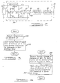
- Figure 1 illustrates a system containing a battery pack comprising series-connected batteries 20.
- the battery pack has a positive terminal (+) and a negative terminal (-), these terminals coupled to an electrical load (not shown) which uses the energy stored in batteries 20. It is also through positive terminal (+) and negative terminal (-) that the battery pack is recharged through connection to a recharger (not shown).
- Module control units 26 are each coupled to a data bus 28, such as the medium-speed serial communications protocol (SCP) bus employed by Ford Motor Company. Other data buses with appropriate bandwidth can be used as well.
- SCP medium-speed serial communications protocol
- Central controller 30 is preferably a microprocessor-based component with sufficient microcomputer resources (throughput, memory, inputs, outputs, data bus interface and the like) to perform the functions ascribed to it in this disclosure.
- Module control unit 26 is preferably very small and is preferably located within the case of its respective battery 20.
- Module control unit 26 includes a microprocessor 40, such as the PIC16C71 microprocessor from Microchip Corporation, although any equivalent microprocessor can be used as well.
- a microprocessor 40 such as the PIC16C71 microprocessor from Microchip Corporation, although any equivalent microprocessor can be used as well.
- an analogue-to-digital (A/D) converter 42 Also included in module control unit 26 is an analogue-to-digital (A/D) converter 42.
- a voltage regulator 44 Further included within module control unit 26 is a voltage regulator 44.
- Voltage regulator 44 provides a regulated voltage V ref , preferably 5 volts DC, for use within module control unit 26.
- V ref for example, is used as a voltage source for microprocessor 40 and A/D converter 42.
- Coupled across the respective battery 20 is a voltage divider comprising resistors 46 and 48. The centre node 50 of this voltage divider is coupled to A/D converter 42, thus allowing module control unit 26 to measure the terminal voltage of battery 20.
- thermistor 52 Also included in module control unit 26 is a thermistor 52.
- Thermistor 52 is provided to measure the temperature of the respective battery 20 to which module control unit 26 is coupled.
- An appropriate pull-up resistor 54 pulls thermistor 52 up to V ref .
- the centre node 56 between thermistor 52 and pull-up resistor 54 is coupled to A/D converter 42.
- Module control unit 26 further includes a resistor 60 which is coupled to an output 62 of microprocessor 40.
- Output 62 of microprocessor 40 is an output which can be pulled LOW in a pulse-width modulated (PWM) manner.
- PWM pulse-width modulated
- the duty cycle at which output 62 is pulled LOW is software-controllable.
- output 62 is HIGH (i.e., about five volts).
- output 62 is LOW (i.e., about zero volts), causing resistor 60 to be shunted across the terminals of battery 20.
- resistor 60 has been selected to be 200 ohms. Therefore, at a 100% LOW duty cycle, output 62 of microprocessor 40 draws 25 milliamperes of current (5 volts / 200 ohms) from battery 20. For lesser duty cycles, output 62 draws less average current from battery 20.
- Module control unit 26 also includes data bus interface circuitry 64 to allow microprocessor 40 to communicate in the appropriate protocol for data bus 28.
- An optical isolator 66 is also employed to assure common-mode voltage isolation between central controller 30 and batteries 20.
- the battery pack comprising the series connection of batteries 20 will in the case of a typical electric vehicle have a voltage of several hundred volts between the (+) and (-) terminals.
- the system of Figures 1 and 2 balances the charge of batteries 20 as will now be described.
- the method which will be described can be performed continuously, when the batteries are "on charge”, being discharged through their intended load (e.g., the electric motor in an electric vehicle) or sitting idle.
- the method can be called “continuous” in that it can continually work prevent large charge imbalances between batteries 20, rather than relying solely on balancing at the end of charge of batteries 20.
- step 100 the temperature of each of batteries 20 is measured. These measurements are done by each module control unit 26, preferably at the command of central controller 30, using the thermistor 52 in each module control unit 26. The temperatures are then reported back to central controller 30.
- Central controller 30 contains in memory a look-up table which contains the typical self-discharge rate of batteries 20 (in units of current) as a function of temperature. This look-up table is populated using empirical data gathered by measuring battery discharge rates in the laboratory or during vehicle development. Generally, the coolest battery 20 will have the lowest self-discharge rate, with successively warmer batteries having successively higher self-discharge rates.
- central controller 30 commands each module control unit 26 to shunt an appropriate amount of current through its resistor 60 and microprocessor output 62 in order to equalise the self-discharge rates of batteries 20.
- the battery 20 with the highest self-discharge rate will not need to shunt any current, while batteries 20 with lower self-discharge rates will need to shunt successively larger amounts of current in order to equalise the self-discharge rates.
- Steps 100 and 102 are repeatedly performed at a predetermined rate.
- the algorithm of Figure 3 substantially reduces the tendency of the states of charge of batteries 20 to become imbalanced due to differing self-discharge rates between batteries 20.
- any imbalance which must be corrected at the end of charging is greatly reduced.
- any known method of balancing at the end of charging such as those mentioned in the Background section of this disclosure, can be applied.
- the reduced charge imbalance which must be corrected at the end of charging greatly reduces a number of the disadvantages, discussed in the Background section of this disclosure, involved in prior art methods of balancing at the end of charging. For example, if a large charging current is used until one battery 20 is charged and then a trickle current is used until the remainder of the batteries 20 are charged, this trickle current will only need to be applied for a relatively short time.
- shunt resistor 62 is 200 ohms in one embodiment of the present invention. With a maximum of five volts across resistor 62, resistor 62 has a V 2 /R power dissipation of only one-eighth watt.
- the continuous charge balancing method of the present invention does not require high-wattage electronic components. This advantage accrues because the continuous charge balancing prevents large charge imbalances from occurring and requiring balancing in a short period of time.
- a second algorithm according to a second embodiment of the present invention is illustrated with reference to Figure 4.
- the terminal voltage of each battery 20 is measured by its respective module control unit 26, preferably at the simultaneous command of central controller 30.
- a simultaneous command can come via a single "broadcast" message on data bus 28, directed to all module control units 26; each module control unit 26 will immediately measure the terminal voltage of its respective battery 20.
- the terminal voltages are then reported back to central controller 30 by module control units 26 as arbitration on data bus 28 will allow. Because batteries 20 are connected in series, the same current is drawn from batteries 20 by their intended electrical load (e.g., the electric motor of an electric vehicle) or provided to batteries 20 by their charger.
- the relative terminal voltages of the batteries are an indication of the relative states of charge of the batteries.
- the batteries with higher terminal voltages will have higher states of charge.
- central controller 30 commands those module control units 26 connected to batteries 20 with higher voltages to shunt current via their shunt resistors 60 and microprocessor outputs 62.
- Those batteries 20 with the highest voltages will be directed to shunt more current.
- the battery 20 with the lowest voltage will not need to shunt any current.
- This algorithm of Figure 4 will help continually prevent or reduce charge imbalances which must be eliminated at the end of charging of batteries 20. The algorithm is performed repeatedly at a predetermined rate.
- the algorithms of Figures 3 and 4 can also "learn" over a number of charge/discharge cycles of batteries 20.
- one or more of batteries 20 may have self-discharge rates which vary from expected nominal values, due to factors such as manufacturing variations. Such differences in self-discharge rates can be learned by observing batteries 20 over a number of charge/discharge cycles, and the charge-balancing algorithms can adaptively recalibrate themselves accordingly.
- module control units 26 can be directed to shunt current based on a three-dimensional function having both temperature and voltage of batteries 20 as independent variables and shunt current as the dependent variable.
Landscapes
- Engineering & Computer Science (AREA)
- Power Engineering (AREA)
- Chemical Kinetics & Catalysis (AREA)
- Chemical & Material Sciences (AREA)
- Electrochemistry (AREA)
- General Chemical & Material Sciences (AREA)
- Manufacturing & Machinery (AREA)
- Life Sciences & Earth Sciences (AREA)
- Sustainable Development (AREA)
- Sustainable Energy (AREA)
- Transportation (AREA)
- Mechanical Engineering (AREA)
- Charge And Discharge Circuits For Batteries Or The Like (AREA)
- Secondary Cells (AREA)
Applications Claiming Priority (2)
| Application Number | Priority Date | Filing Date | Title |
|---|---|---|---|
| US669260 | 1996-06-21 | ||
| US08/669,260 US5764027A (en) | 1996-06-21 | 1996-06-21 | Method and apparatus for battery charge balancing |
Publications (3)
| Publication Number | Publication Date |
|---|---|
| EP0814556A2 true EP0814556A2 (de) | 1997-12-29 |
| EP0814556A3 EP0814556A3 (de) | 1998-11-11 |
| EP0814556B1 EP0814556B1 (de) | 2006-01-11 |
Family
ID=24685715
Family Applications (1)
| Application Number | Title | Priority Date | Filing Date |
|---|---|---|---|
| EP97303936A Expired - Lifetime EP0814556B1 (de) | 1996-06-21 | 1997-06-06 | Verfahren zum Batterieladungsausgleich |
Country Status (4)
| Country | Link |
|---|---|
| US (1) | US5764027A (de) |
| EP (1) | EP0814556B1 (de) |
| JP (1) | JPH1066270A (de) |
| DE (1) | DE69735080T2 (de) |
Cited By (21)
| Publication number | Priority date | Publication date | Assignee | Title |
|---|---|---|---|---|
| EP0932240A2 (de) * | 1997-12-26 | 1999-07-28 | Hitachi, Ltd. | Batteriesystem und Elektrofahrzeug welches dieses Batteriesystem verwendet |
| WO2000016462A1 (en) * | 1998-09-17 | 2000-03-23 | Qualcomm Incorporated | Battery pack controller |
| EP1220414A2 (de) * | 2000-12-28 | 2002-07-03 | C.E. NIEHOFF & COMPANY | Ladungsausgleichsschaltung einer Vielzahl von Batterien |
| EP1408574A2 (de) * | 2002-10-08 | 2004-04-14 | Alps Electric Co., Ltd. | Batterievorrichtung |
| WO2005091461A1 (de) * | 2004-03-17 | 2005-09-29 | Effekta Regeltechnik Gmbh | Vorrichtung zur ladeverteilung und überwachung von mehreren akkumulatoren |
| EP1771930A2 (de) * | 2004-07-28 | 2007-04-11 | EnerDel, Inc. | Verfahren und vorrichtung zum ausgleich von mehrzellenlithiumbatteriesystemen |
| EP1978577A1 (de) * | 2007-04-05 | 2008-10-08 | Ferm B.V. | Batterie mit mehreren Zellen, Batterieanordnung, Leistungswerkzeug und Verfahren zum Ausgleich der Spannungsniveaus der Batteriezellen |
| EP2075894A2 (de) * | 2007-12-27 | 2009-07-01 | Sanyo Electric Co., Ltd. | Vorrichtung zum Ausgleichen des Ladezustands und zusammengesetztes Batteriesystem, das diese Vorrichtung enthält |
| WO2009146976A1 (de) * | 2008-06-03 | 2009-12-10 | Robert Bosch Gmbh | Vorrichtung und verfahren zum ladezustandsausgleich von fahrzeug-batterien |
| WO2010011458A2 (en) * | 2008-07-24 | 2010-01-28 | General Electric Company | Method and system for extending life of a vehicle energy storage device |
| GB2465469A (en) * | 2008-11-19 | 2010-05-26 | Hitachi Ltd | Power storage control system |
| EP2385604A1 (de) | 2010-05-07 | 2011-11-09 | Brusa Elektronik AG | Verfahren und Zellüberwachungseinheit zur Überwachung eines Akkumulators, zentrale Überwachungseinheit und Akkumulator |
| CN102303541A (zh) * | 2011-06-20 | 2012-01-04 | 安徽安凯汽车股份有限公司 | 一种增程式电动汽车的蓄电池电量管理方法 |
| WO2012032428A1 (en) | 2010-09-07 | 2012-03-15 | Brusa Elektronik Ag | Method and cell monitoring unit for monitoring a rechargeable battery |
| CN103107565A (zh) * | 2011-11-15 | 2013-05-15 | 赵俊义 | 电动汽车电池管理系统静态均衡方法 |
| DE102012204966A1 (de) * | 2012-03-28 | 2013-10-02 | Robert Bosch Gmbh | Batteriesystem mit Balancing-Schaltung |
| CN105480106A (zh) * | 2015-11-20 | 2016-04-13 | 浙江超威创元实业有限公司 | 电动汽车锂电池管理装置及控制方法 |
| CN108284762A (zh) * | 2018-01-23 | 2018-07-17 | 苏州妙益科技股份有限公司 | 一种动力电池组管理系统 |
| CN109428356A (zh) * | 2017-08-31 | 2019-03-05 | 比亚迪股份有限公司 | 电池均衡方法、系统、车辆、存储介质及电子设备 |
| CN110015186A (zh) * | 2017-08-31 | 2019-07-16 | 比亚迪股份有限公司 | 电池均衡方法、系统、车辆、存储介质及电子设备 |
| CN111751737A (zh) * | 2020-07-07 | 2020-10-09 | 安徽江淮汽车集团股份有限公司 | 动力电池的自放电电流计算方法、装置、设备及存储介质 |
Families Citing this family (38)
| Publication number | Priority date | Publication date | Assignee | Title |
|---|---|---|---|---|
| US6271645B1 (en) | 2000-02-11 | 2001-08-07 | Delphi Technologies, Inc. | Method for balancing battery pack energy levels |
| US6781817B2 (en) * | 2000-10-02 | 2004-08-24 | Biosource, Inc. | Fringe-field capacitor electrode for electrochemical device |
| US6583602B2 (en) * | 2001-05-11 | 2003-06-24 | Denso Corporation | Vehicular power supply apparatus and method of controlling the same |
| US7615966B2 (en) * | 2001-05-25 | 2009-11-10 | Texas Instruments Northern Virginia Incorporated | Method and apparatus for managing energy in plural energy storage units |
| US20040121204A1 (en) * | 2001-06-07 | 2004-06-24 | Adelman Marc D. | Fluid electrical connected flow-through electrochemical cells, system and method |
| US6661203B2 (en) * | 2001-11-12 | 2003-12-09 | Hewlett-Packard Development Company, L.P. | Battery charging and discharging system optimized for high temperature environments |
| CN1317802C (zh) * | 2002-08-05 | 2007-05-23 | 财团法人工业技术研究院 | 一种用于电池管理系统的可扩充式电池状态监测电路 |
| WO2004049540A2 (en) * | 2002-11-25 | 2004-06-10 | Tiax Llc | Cell balancing system for equalizing state of charge among series-connected electrical energy storage units |
| US20070080664A1 (en) * | 2005-07-29 | 2007-04-12 | Ford Global Technologies, Llc | System and method for rebalancing a battery during vehicle operation |
| JP2007157403A (ja) * | 2005-12-01 | 2007-06-21 | Sanyo Electric Co Ltd | 電源装置 |
| EP2092627B1 (de) | 2006-11-10 | 2018-05-23 | Lithium Balance A/S | Batterie-verwaltungssystem |
| EP2075893B1 (de) * | 2007-10-15 | 2016-03-09 | Black & Decker, Inc. | Unterseitenbasierter Ausgleich in einem Lithiumionenbatteriesystem |
| US8264207B2 (en) * | 2007-10-16 | 2012-09-11 | Ford Global Technologies, Llc | Method and system for pulse charging an automotive battery |
| US8426063B2 (en) * | 2008-02-15 | 2013-04-23 | Atieva, Inc. | Method of electrically connecting cell terminals in a battery pack |
| US20090243540A1 (en) * | 2008-04-01 | 2009-10-01 | Analog Express Inc. | Methods and apparatus for battery charging management |
| US10283974B2 (en) * | 2009-03-02 | 2019-05-07 | Volterra Semiconductor LLC | Systems and methods for intelligent, adaptive management of energy storage packs |
| US9397502B2 (en) | 2009-03-02 | 2016-07-19 | Volterra Semiconductor LLC | System and method for proportioned power distribution in power converter arrays |
| US8143863B2 (en) * | 2009-10-12 | 2012-03-27 | O2Micro, Inc | Circuits and methods for controlling a current flowing through a battery |
| JP5467597B2 (ja) * | 2010-03-01 | 2014-04-09 | 株式会社ピューズ | 組電池 |
| US8872518B2 (en) | 2010-06-25 | 2014-10-28 | Atieva, Inc. | Determining the state of-charge of batteries via selective sampling of extrapolated open circuit voltage |
| CN101882699B (zh) * | 2010-06-28 | 2012-12-05 | 惠州市亿能电子有限公司 | 动力电池组充放电均衡控制方法 |
| US8030894B2 (en) | 2010-08-03 | 2011-10-04 | Ford Global Technologies, Llc | System and method for rebalancing a vehicle battery |
| US8922167B2 (en) * | 2011-01-20 | 2014-12-30 | Valence Technology, Inc. | Rechargeable battery systems and rechargeable battery system operational methods |
| US8957624B2 (en) | 2011-01-20 | 2015-02-17 | Valence Technology, Inc. | Rechargeable battery systems and rechargeable battery system operational methods |
| US8773068B2 (en) | 2011-01-20 | 2014-07-08 | Valence Technology, Inc. | Rechargeable battery systems and rechargeable battery system operational methods |
| JP5505375B2 (ja) * | 2011-06-29 | 2014-05-28 | 株式会社豊田自動織機 | セルバランス制御装置及びセルバランス制御方法 |
| US9559529B1 (en) | 2011-07-28 | 2017-01-31 | The United States Of America As Represented By The Administrator Of National Aeronautics And Space Administration | Modular battery controller |
| US9404956B2 (en) * | 2011-12-19 | 2016-08-02 | Ford Global Technologies, Llc | Vehicle with selectable battery pack isolation detection circuitry using precision resistors |
| DE102012202690A1 (de) * | 2012-02-22 | 2013-08-22 | Bayerische Motoren Werke Aktiengesellschaft | Fahrzeug |
| US20130257381A1 (en) * | 2012-03-29 | 2013-10-03 | Steven Diamond | Peak-equalized battery charge balancing |
| DE102013008359A1 (de) * | 2013-05-16 | 2014-11-20 | Sew-Eurodrive Gmbh & Co Kg | Energiespeicher, der aus in Reihe geschalten Energiespeicherzellen aufgebaut ist, und Schaltungsanordnung zur passiven Symmetrierung einer Reihenschaltung von Kondensatoren |
| US20150207344A1 (en) * | 2014-01-17 | 2015-07-23 | General Electric Company | Configurable hybrid energy storage system and method |
| US9827865B2 (en) | 2014-12-30 | 2017-11-28 | General Electric Company | Systems and methods for recharging vehicle-mounted energy storage devices |
| US10300804B2 (en) | 2015-04-29 | 2019-05-28 | General Electric Company | Apparatus and method for automated positioning of a vehicle |
| US9987938B2 (en) | 2015-12-04 | 2018-06-05 | General Electric Company | Energy storage device, exchange apparatus, and method for exchanging an energy storage device |
| CN109017381B (zh) * | 2018-07-31 | 2021-09-24 | 电子科技大学 | 一种动力电池组复合均衡控制方法 |
| CN111873852B (zh) * | 2020-07-01 | 2022-02-11 | 广州小鹏汽车科技有限公司 | 一种动力电池自放电监测方法及装置、车辆、存储介质 |
| TR2022012880A2 (tr) * | 2022-08-15 | 2022-09-21 | Gaziantep Ueniversitesi Rektoerluegue | Batarya enerji̇ depolama si̇stemleri̇ i̇çi̇n hata toleransli ve adapti̇f şarj durumu dengeleme yöntemi̇ |
Citations (3)
| Publication number | Priority date | Publication date | Assignee | Title |
|---|---|---|---|---|
| EP0652620A1 (de) * | 1993-10-14 | 1995-05-10 | FIAT AUTO S.p.A. | Verfahren zum Spannungsaufgleich von in Reihen geschalteten Traktionbatterien für Elektrische Fahrzeuge während der wiederaufladung und Vorrichtung zur Durchführung dieses Verfahrens |
| EP0731545A2 (de) * | 1995-03-03 | 1996-09-11 | Motorola, Inc. | Schaltung und Verfahren zur Batterieladesteuerung |
| US5565759A (en) * | 1994-12-15 | 1996-10-15 | Intel Corporation | Smart battery providing battery life and recharge time prediction |
Family Cites Families (13)
| Publication number | Priority date | Publication date | Assignee | Title |
|---|---|---|---|---|
| GB1461616A (en) * | 1973-04-10 | 1977-01-13 | Mabuchi Motor Co | Battery equalizing discharger |
| US3997830A (en) * | 1974-11-27 | 1976-12-14 | Rca Corporation | Satellite battery reconditioning system and method |
| US4238721A (en) * | 1979-02-06 | 1980-12-09 | The United States Of America As Represented By The United States Department Of Energy | System and method for charging electrochemical cells in series |
| SE451924B (sv) * | 1982-10-12 | 1987-11-02 | Ericsson Telefon Ab L M | Regulator for reglering av en laddningsstrom till en enskild cell i ett batteri av celler |
| DE3326729A1 (de) * | 1983-07-25 | 1985-02-07 | Siemens AG, 1000 Berlin und 8000 München | Verfahren zum betrieb eines elektrochemischen speichers |
| US5153496A (en) * | 1990-09-27 | 1992-10-06 | Baxtrer International Inc. | Cell monitor and control unit for multicell battery |
| US5063340A (en) * | 1990-10-25 | 1991-11-05 | Motorola, Inc. | Capacitive power supply having charge equalization circuit |
| JP3231801B2 (ja) * | 1991-02-08 | 2001-11-26 | 本田技研工業株式会社 | バッテリの充電装置 |
| US5283512A (en) * | 1992-04-13 | 1994-02-01 | Hughes Aircraft Company | Charge balancing of batteries during charging |
| US5488282A (en) * | 1993-06-23 | 1996-01-30 | Hughes Aircraft Company | System and method for reconditioning spacecraft battery |
| US5504415A (en) * | 1993-12-03 | 1996-04-02 | Electronic Power Technology, Inc. | Method and apparatus for automatic equalization of series-connected batteries |
| US5498950A (en) * | 1994-04-29 | 1996-03-12 | Delco Electronics Corp. | Battery monitoring, charging and balancing apparatus |
| JPH07336905A (ja) * | 1994-06-08 | 1995-12-22 | Nissan Motor Co Ltd | 組電池の充電装置 |
-
1996
- 1996-06-21 US US08/669,260 patent/US5764027A/en not_active Expired - Lifetime
-
1997
- 1997-04-14 JP JP9096098A patent/JPH1066270A/ja active Pending
- 1997-06-06 DE DE69735080T patent/DE69735080T2/de not_active Expired - Lifetime
- 1997-06-06 EP EP97303936A patent/EP0814556B1/de not_active Expired - Lifetime
Patent Citations (3)
| Publication number | Priority date | Publication date | Assignee | Title |
|---|---|---|---|---|
| EP0652620A1 (de) * | 1993-10-14 | 1995-05-10 | FIAT AUTO S.p.A. | Verfahren zum Spannungsaufgleich von in Reihen geschalteten Traktionbatterien für Elektrische Fahrzeuge während der wiederaufladung und Vorrichtung zur Durchführung dieses Verfahrens |
| US5565759A (en) * | 1994-12-15 | 1996-10-15 | Intel Corporation | Smart battery providing battery life and recharge time prediction |
| EP0731545A2 (de) * | 1995-03-03 | 1996-09-11 | Motorola, Inc. | Schaltung und Verfahren zur Batterieladesteuerung |
Cited By (37)
| Publication number | Priority date | Publication date | Assignee | Title |
|---|---|---|---|---|
| EP0932240A3 (de) * | 1997-12-26 | 1999-08-25 | Hitachi, Ltd. | Batteriesystem und Elektrofahrzeug welches dieses Batteriesystem verwendet |
| US6262561B1 (en) | 1997-12-26 | 2001-07-17 | Hitachi, Ltd. | Battery system and electric vehicle using the battery system |
| EP0932240A2 (de) * | 1997-12-26 | 1999-07-28 | Hitachi, Ltd. | Batteriesystem und Elektrofahrzeug welches dieses Batteriesystem verwendet |
| WO2000016462A1 (en) * | 1998-09-17 | 2000-03-23 | Qualcomm Incorporated | Battery pack controller |
| AU783472B2 (en) * | 2000-12-28 | 2005-10-27 | C.E. Niehoff & Company | Multiple battery charge equalizer |
| EP1220414A2 (de) * | 2000-12-28 | 2002-07-03 | C.E. NIEHOFF & COMPANY | Ladungsausgleichsschaltung einer Vielzahl von Batterien |
| EP1220414A3 (de) * | 2000-12-28 | 2004-06-30 | C.E. NIEHOFF & COMPANY | Ladungsausgleichsschaltung einer Vielzahl von Batterien |
| EP1408574A2 (de) * | 2002-10-08 | 2004-04-14 | Alps Electric Co., Ltd. | Batterievorrichtung |
| EP1408574A3 (de) * | 2002-10-08 | 2005-09-21 | Alps Electric Co., Ltd. | Batterievorrichtung |
| WO2005091461A1 (de) * | 2004-03-17 | 2005-09-29 | Effekta Regeltechnik Gmbh | Vorrichtung zur ladeverteilung und überwachung von mehreren akkumulatoren |
| DE102004013351A1 (de) * | 2004-03-17 | 2005-10-06 | Effekta Regeltechnik Gmbh | Vorrichtung zur Ladeverteilung und Überwachung von mehreren Akkumulatoren |
| EP1771930A2 (de) * | 2004-07-28 | 2007-04-11 | EnerDel, Inc. | Verfahren und vorrichtung zum ausgleich von mehrzellenlithiumbatteriesystemen |
| EP1771930A4 (de) * | 2004-07-28 | 2010-09-01 | Enerdel Inc | Verfahren und vorrichtung zum ausgleich von mehrzellenlithiumbatteriesystemen |
| EP1978577A1 (de) * | 2007-04-05 | 2008-10-08 | Ferm B.V. | Batterie mit mehreren Zellen, Batterieanordnung, Leistungswerkzeug und Verfahren zum Ausgleich der Spannungsniveaus der Batteriezellen |
| EP2075894A2 (de) * | 2007-12-27 | 2009-07-01 | Sanyo Electric Co., Ltd. | Vorrichtung zum Ausgleichen des Ladezustands und zusammengesetztes Batteriesystem, das diese Vorrichtung enthält |
| US7923969B2 (en) | 2007-12-27 | 2011-04-12 | Sanyo Electric Co., Ltd. | State of charge equalizing device and assembled battery system including same |
| EP2075894A3 (de) * | 2007-12-27 | 2011-02-02 | Sanyo Electric Co., Ltd. | Vorrichtung zum Ausgleichen des Ladezustands und zusammengesetztes Batteriesystem, das diese Vorrichtung enthält |
| WO2009146976A1 (de) * | 2008-06-03 | 2009-12-10 | Robert Bosch Gmbh | Vorrichtung und verfahren zum ladezustandsausgleich von fahrzeug-batterien |
| WO2010011458A2 (en) * | 2008-07-24 | 2010-01-28 | General Electric Company | Method and system for extending life of a vehicle energy storage device |
| WO2010011458A3 (en) * | 2008-07-24 | 2011-10-06 | General Electric Company | Method and system for extending life of a vehicle energy storage device |
| GB2465469B (en) * | 2008-11-19 | 2010-12-29 | Hitachi Ltd | Power circuit control system |
| GB2465469A (en) * | 2008-11-19 | 2010-05-26 | Hitachi Ltd | Power storage control system |
| CN101740826B (zh) * | 2008-11-19 | 2013-07-17 | 株式会社日立制作所 | 电池电路控制系统 |
| EP2385604A1 (de) | 2010-05-07 | 2011-11-09 | Brusa Elektronik AG | Verfahren und Zellüberwachungseinheit zur Überwachung eines Akkumulators, zentrale Überwachungseinheit und Akkumulator |
| WO2011138726A2 (en) | 2010-05-07 | 2011-11-10 | Brusa Elektronik Ag | Method and cell monitoring unit for monitoring an accumulator; central monitoring unit and accumulator |
| WO2012032428A1 (en) | 2010-09-07 | 2012-03-15 | Brusa Elektronik Ag | Method and cell monitoring unit for monitoring a rechargeable battery |
| CN102303541A (zh) * | 2011-06-20 | 2012-01-04 | 安徽安凯汽车股份有限公司 | 一种增程式电动汽车的蓄电池电量管理方法 |
| CN103107565A (zh) * | 2011-11-15 | 2013-05-15 | 赵俊义 | 电动汽车电池管理系统静态均衡方法 |
| DE102012204966A1 (de) * | 2012-03-28 | 2013-10-02 | Robert Bosch Gmbh | Batteriesystem mit Balancing-Schaltung |
| CN105480106A (zh) * | 2015-11-20 | 2016-04-13 | 浙江超威创元实业有限公司 | 电动汽车锂电池管理装置及控制方法 |
| CN109428356A (zh) * | 2017-08-31 | 2019-03-05 | 比亚迪股份有限公司 | 电池均衡方法、系统、车辆、存储介质及电子设备 |
| CN110015186A (zh) * | 2017-08-31 | 2019-07-16 | 比亚迪股份有限公司 | 电池均衡方法、系统、车辆、存储介质及电子设备 |
| CN109428356B (zh) * | 2017-08-31 | 2022-02-08 | 比亚迪股份有限公司 | 电池均衡方法、系统、车辆、存储介质及电子设备 |
| CN110015186B (zh) * | 2017-08-31 | 2023-02-10 | 比亚迪股份有限公司 | 电池均衡方法、系统、车辆、存储介质及电子设备 |
| CN108284762A (zh) * | 2018-01-23 | 2018-07-17 | 苏州妙益科技股份有限公司 | 一种动力电池组管理系统 |
| CN111751737A (zh) * | 2020-07-07 | 2020-10-09 | 安徽江淮汽车集团股份有限公司 | 动力电池的自放电电流计算方法、装置、设备及存储介质 |
| CN111751737B (zh) * | 2020-07-07 | 2021-10-01 | 安徽江淮汽车集团股份有限公司 | 动力电池的自放电电流计算方法、装置、设备及存储介质 |
Also Published As
| Publication number | Publication date |
|---|---|
| EP0814556B1 (de) | 2006-01-11 |
| JPH1066270A (ja) | 1998-03-06 |
| US5764027A (en) | 1998-06-09 |
| DE69735080D1 (de) | 2006-04-06 |
| EP0814556A3 (de) | 1998-11-11 |
| DE69735080T2 (de) | 2006-11-09 |
Similar Documents
| Publication | Publication Date | Title |
|---|---|---|
| US5764027A (en) | Method and apparatus for battery charge balancing | |
| US6064178A (en) | Battery charge balancing system having parallel switched energy storage elements | |
| EP1568114B1 (de) | Zellausgleichssystem zum ausgleich des ladezustandes unter reihengeschalteten elektrischen energiespeichereinheiten | |
| US9537330B2 (en) | System and method for electrical vehicle battery management | |
| CN103947066B (zh) | 用于平衡电力电池组元件的充电的装置 | |
| US8598847B2 (en) | Balancing voltage for a multi-cell battery system | |
| EP1396063B1 (de) | Schaltung zur zellen-stromüberwachung einer mehrzelligen batterie während der batterieladung | |
| KR101227747B1 (ko) | 리치움밧데리 시스템에 대한 셀 바란싱 방법 | |
| JP3922655B2 (ja) | 電源装置の制御システムおよび電源装置の制御方法 | |
| US6271645B1 (en) | Method for balancing battery pack energy levels | |
| CN108886264B (zh) | 单元平衡方法和系统 | |
| JP5394563B2 (ja) | バッテリ制御装置、バッテリシステム、電動車両、充電制御装置、充電器、移動体、電源システム、電力貯蔵装置および電源装置 | |
| WO2017130614A1 (ja) | 電池制御装置 | |
| EP2367261A2 (de) | Gleichstromquellenvorrichtung | |
| JP2003303627A (ja) | 状態検知装置及びこれを用いた各種装置 | |
| AU2020377184A1 (en) | Method for charging and/or discharging a rechargeable energy store | |
| CN114194041A (zh) | 估计电池的充满电时间的方法、动力系控制器和电动车辆 | |
| JP2001145273A (ja) | 組電池の充電制御装置 | |
| JP3629791B2 (ja) | 組電池の充電制御装置 | |
| JP3409458B2 (ja) | 組電池の充電装置 | |
| WO2003003028A1 (en) | Accurate battery current measurement system for a battery care unit | |
| JPH10262342A (ja) | 充電装置 | |
| CN115173496A (zh) | 动态电池充电平衡装置与方法以及可充电电池装置 | |
| EP3987626A1 (de) | Batterieverwaltungssystem zum parallelen laden von batteriemodulen | |
| SE2250710A1 (en) | Programmable charging system for a plurality of rechargable batteries |
Legal Events
| Date | Code | Title | Description |
|---|---|---|---|
| PUAI | Public reference made under article 153(3) epc to a published international application that has entered the european phase |
Free format text: ORIGINAL CODE: 0009012 |
|
| AK | Designated contracting states |
Kind code of ref document: A2 Designated state(s): DE FR GB |
|
| PUAL | Search report despatched |
Free format text: ORIGINAL CODE: 0009013 |
|
| AK | Designated contracting states |
Kind code of ref document: A3 Designated state(s): AT BE CH DE DK ES FI FR GB GR IE IT LI LU MC NL PT SE |
|
| 17P | Request for examination filed |
Effective date: 19981127 |
|
| AKX | Designation fees paid |
Free format text: DE FR GB |
|
| 17Q | First examination report despatched |
Effective date: 20050202 |
|
| GRAP | Despatch of communication of intention to grant a patent |
Free format text: ORIGINAL CODE: EPIDOSNIGR1 |
|
| RTI1 | Title (correction) |
Free format text: METHOD FOR BATTERY CHARGE BALANCING |
|
| GRAS | Grant fee paid |
Free format text: ORIGINAL CODE: EPIDOSNIGR3 |
|
| GRAA | (expected) grant |
Free format text: ORIGINAL CODE: 0009210 |
|
| AK | Designated contracting states |
Kind code of ref document: B1 Designated state(s): DE FR GB |
|
| REF | Corresponds to: |
Ref document number: 69735080 Country of ref document: DE Date of ref document: 20060406 Kind code of ref document: P |
|
| PGFP | Annual fee paid to national office [announced via postgrant information from national office to epo] |
Ref country code: FR Payment date: 20060605 Year of fee payment: 10 |
|
| PLBE | No opposition filed within time limit |
Free format text: ORIGINAL CODE: 0009261 |
|
| STAA | Information on the status of an ep patent application or granted ep patent |
Free format text: STATUS: NO OPPOSITION FILED WITHIN TIME LIMIT |
|
| 26N | No opposition filed |
Effective date: 20061012 |
|
| EN | Fr: translation not filed | ||
| PG25 | Lapsed in a contracting state [announced via postgrant information from national office to epo] |
Ref country code: FR Free format text: LAPSE BECAUSE OF FAILURE TO SUBMIT A TRANSLATION OF THE DESCRIPTION OR TO PAY THE FEE WITHIN THE PRESCRIBED TIME-LIMIT Effective date: 20070302 |
|
| REG | Reference to a national code |
Ref country code: DE Ref legal event code: R082 Ref document number: 69735080 Country of ref document: DE Representative=s name: DOERFLER, THOMAS, DR.-ING., DE |
|
| PGFP | Annual fee paid to national office [announced via postgrant information from national office to epo] |
Ref country code: GB Payment date: 20160525 Year of fee payment: 20 |
|
| PGFP | Annual fee paid to national office [announced via postgrant information from national office to epo] |
Ref country code: DE Payment date: 20160629 Year of fee payment: 20 |
|
| REG | Reference to a national code |
Ref country code: DE Ref legal event code: R071 Ref document number: 69735080 Country of ref document: DE |
|
| REG | Reference to a national code |
Ref country code: GB Ref legal event code: PE20 Expiry date: 20170605 |
|
| PG25 | Lapsed in a contracting state [announced via postgrant information from national office to epo] |
Ref country code: GB Free format text: LAPSE BECAUSE OF EXPIRATION OF PROTECTION Effective date: 20170605 |