EP0813941A2 - Machine tool for working elongated material - Google Patents
Machine tool for working elongated material Download PDFInfo
- Publication number
- EP0813941A2 EP0813941A2 EP97109751A EP97109751A EP0813941A2 EP 0813941 A2 EP0813941 A2 EP 0813941A2 EP 97109751 A EP97109751 A EP 97109751A EP 97109751 A EP97109751 A EP 97109751A EP 0813941 A2 EP0813941 A2 EP 0813941A2
- Authority
- EP
- European Patent Office
- Prior art keywords
- tool spindle
- machine according
- spindle
- workpiece
- joinery
- Prior art date
- Legal status (The legal status is an assumption and is not a legal conclusion. Google has not performed a legal analysis and makes no representation as to the accuracy of the status listed.)
- Granted
Links
Images
Classifications
-
- B—PERFORMING OPERATIONS; TRANSPORTING
- B27—WORKING OR PRESERVING WOOD OR SIMILAR MATERIAL; NAILING OR STAPLING MACHINES IN GENERAL
- B27M—WORKING OF WOOD NOT PROVIDED FOR IN SUBCLASSES B27B - B27L; MANUFACTURE OF SPECIFIC WOODEN ARTICLES
- B27M1/00—Working of wood not provided for in subclasses B27B - B27L, e.g. by stretching
- B27M1/08—Working of wood not provided for in subclasses B27B - B27L, e.g. by stretching by multi-step processes
-
- B—PERFORMING OPERATIONS; TRANSPORTING
- B23—MACHINE TOOLS; METAL-WORKING NOT OTHERWISE PROVIDED FOR
- B23Q—DETAILS, COMPONENTS, OR ACCESSORIES FOR MACHINE TOOLS, e.g. ARRANGEMENTS FOR COPYING OR CONTROLLING; MACHINE TOOLS IN GENERAL CHARACTERISED BY THE CONSTRUCTION OF PARTICULAR DETAILS OR COMPONENTS; COMBINATIONS OR ASSOCIATIONS OF METAL-WORKING MACHINES, NOT DIRECTED TO A PARTICULAR RESULT
- B23Q7/00—Arrangements for handling work specially combined with or arranged in, or specially adapted for use in connection with, machine tools, e.g. for conveying, loading, positioning, discharging, sorting
- B23Q7/06—Arrangements for handling work specially combined with or arranged in, or specially adapted for use in connection with, machine tools, e.g. for conveying, loading, positioning, discharging, sorting by means of pushers
-
- B—PERFORMING OPERATIONS; TRANSPORTING
- B23—MACHINE TOOLS; METAL-WORKING NOT OTHERWISE PROVIDED FOR
- B23Q—DETAILS, COMPONENTS, OR ACCESSORIES FOR MACHINE TOOLS, e.g. ARRANGEMENTS FOR COPYING OR CONTROLLING; MACHINE TOOLS IN GENERAL CHARACTERISED BY THE CONSTRUCTION OF PARTICULAR DETAILS OR COMPONENTS; COMBINATIONS OR ASSOCIATIONS OF METAL-WORKING MACHINES, NOT DIRECTED TO A PARTICULAR RESULT
- B23Q7/00—Arrangements for handling work specially combined with or arranged in, or specially adapted for use in connection with, machine tools, e.g. for conveying, loading, positioning, discharging, sorting
- B23Q7/14—Arrangements for handling work specially combined with or arranged in, or specially adapted for use in connection with, machine tools, e.g. for conveying, loading, positioning, discharging, sorting co-ordinated in production lines
- B23Q7/141—Arrangements for handling work specially combined with or arranged in, or specially adapted for use in connection with, machine tools, e.g. for conveying, loading, positioning, discharging, sorting co-ordinated in production lines with a series disposition of different working devices and with the axial transport for long workpieces of which a plurality of final products are made
-
- B—PERFORMING OPERATIONS; TRANSPORTING
- B27—WORKING OR PRESERVING WOOD OR SIMILAR MATERIAL; NAILING OR STAPLING MACHINES IN GENERAL
- B27C—PLANING, DRILLING, MILLING, TURNING OR UNIVERSAL MACHINES FOR WOOD OR SIMILAR MATERIAL
- B27C9/00—Multi-purpose machines; Universal machines; Equipment therefor
- B27C9/02—Multi-purpose machines; Universal machines; Equipment therefor with a single working spindle
Definitions
- the invention relates to a joinery machine for processing strand material, in particular for processing rod-shaped wooden workpieces, wooden beams, boards and the like, which rest on a support and are transported by a transport device, at least one processing unit arranged along the transport device with a tool spindle driven by a spindle drive , which is displaceable in one plane and on which a tool for machining the workpiece is arranged.
- a joinery machine of this type is known from DE-OS 42 08 233.
- the joinery machine described there has an elongated support for the workpiece and a transport device with which the workpiece can be transported along the support.
- the transport device has a driver which can be connected to the workpiece and, driven by a motor along a guide rail running parallel to the support, pulls the workpiece through the joinery machine.
- joinery systems described above are used to mechanically support the elaborate manual work of a carpenter.
- the joinery system is connected to a computer control, which takes over the data from a construction program and uses this data to determine the corresponding processing steps for the creation of a corresponding wooden workpiece for a roof structure or other wooden structure.
- the joinery machine has a variety of different processing units that are used according to the specifications of the control system according to the construction plan. Exact processing is achieved by the exact guidance of the piece of wood through the transport device.
- joinery machine is that the previously complex manual work is now fully automated by the carpenter. This effect is further intensified by the increasing use of computers in the construction of the roof trusses, since automated joinery systems take over the data for the processing of the workpieces directly from the computer of the designer of the roof truss via a CNC control.
- a CNC-controlled joinery machine is known from DE-PS 34 20 080.
- joinery work is also possible, for example the manufacture of prefabricated houses, etc. using the joinery systems described above.
- the workpiece passes through at least one, but usually several different processing units, which process the workpiece by the usual methods such as milling, drilling or sawing.
- Longitudinal machining such as the introduction of longitudinal grooves, chamfering edges or the like, as well as transverse machining, such as cutting to a certain angle or the introduction of transverse grooves or bores for pins, etc., are carried out on the workpiece.
- a wide variety of tools are required to carry out these various machining steps, such as face and radial milling cutters, round and angular radial milling cutters, various drills or saws.
- a disadvantage of the generic joinery systems is that separate processing units arranged one behind the other must either be provided for the various processing steps to be carried out on the respective workpiece or, if a suitable processing unit is already present in the system, the tool is changed after the first processing and the workpiece must be sent through the system again for further processing.
- This disadvantage arises not only when different machining steps on a workpiece are required, but also when several workpieces are to be machined one after the other, with different machining operations being to be carried out on the different workpieces.
- the tool spindle of a joinery machine of the type mentioned at the outset is rotatable about an axis of rotation perpendicular to the spindle axis and the spindle drive drives a plurality of tools.
- the inventive configuration of the joinery machine makes it possible to arrange several tools that can be used independently of one another on the tool spindle of a processing unit. As a result, the number of processing units required can be significantly reduced, which also reduces the size of the system. Because the position of the tool spindle relative to the workpiece can be changed as required, a large spectrum of different tools can be arranged on a spindle.
- the tool spindle can be mounted in its central region, so that it has two free ends protruding from the mounting, which can be equipped with tools.
- an end mill can be arranged, with which the end face of the workpiece can be machined on the one hand, and, with the tool spindle rotated through 90 ° and correspondingly in the plane transverse to the workpiece, the sides of the workpiece can be machined.
- another tool is arranged, with which other processing steps are carried out.
- a radial milling cutter with a relatively large outside diameter can be used, on the side of which, facing away from the spindle bearing, a small end mill is arranged as a face milling cutter.
- a tool combination of this type grooves can be produced by the radial milling cutter as well as recesses by the face milling cutter.
- the processing unit only moves to the required position by positioning the axis of rotation of the tool spindle accordingly by transversely moving the processing unit and bringing the required tool into the processing position by rotating the tool spindle about the axis perpendicular to the spindle.
- the tools are arranged one behind the other on one side of the tool spindle, for example.
- the tool spindle it is also possible for the tool spindle to have a drive arranged centrally in the middle, and for the two ends of the tool spindle to carry one or more tools.
- several radial milling cutters can be arranged side by side.
- either two mutually parallel grooves can be milled in one operation or, if the distance between the two radial milling cutters is greater than the width of the workpiece to be machined, different groove shapes can be produced.
- An angular milling cutter can thus be provided for producing a rectangular groove, while a rounded radial milling cutter arranged at a distance next to this can produce an internal circular groove.
- the tool spindle which is arranged at right angles to the workpiece, is simply moved a corresponding distance across the workpiece.
- almost any number of milling cutters and saw blades can be arranged side by side.
- an end mill or end mill is arranged at the outer end of the tool spindle.
- This end mill or end mill is combined, for example, with a radial mill with a correspondingly large diameter.
- This radial milling cutter has, for example, a length of approximately 10 cm and a diameter of up to 40 cm.
- the combination of a large and a relatively small milling cutter increases the flexibility of the joinery system considerably.
- the arrangement of the outer end mill is used, for example, for fine machining of surfaces, for example as a router. Instead of the end mill or end mill, it is also possible to use a drill.
- the tool spindle is mounted in the end region of a pedestal and the opposite end of the pedestal is fastened to a rotatably mounted turntable which is driven by an actuator, the turntable being displaceable in the essentially vertically oriented plane.
- the versatility of the joinery system according to the invention is based on the displaceability of the tool spindle in a plane which is angled to the feed direction and the rotatability of the tool spindle about an axis of rotation perpendicular to the spindle axis.
- the plane in which the tool spindle can be moved is arranged at right angles to the feed direction. With horizontal feed, the tool spindle can then be moved to any desired position by a transverse movement perpendicular to the feed direction and a vertical movement.
- the spindle, together with the spindle drive is arranged on a rotatable pedestal which is mounted on a support frame which can be displaced in the essentially vertically oriented plane.
- the base with the spindle drive and the tool spindle can also be arranged on a carrier element which can be moved around the workpiece in a circular or elliptical path.
- the transport device and the support for the workpiece can be enclosed by a circular or elliptical guide rail, for example a rounded toothed rack, on which the motor-driven carrier element can be moved.
- a circular or elliptical guide rail for example a rounded toothed rack
- the base can be designed as a telescopic rod, with the spindle drive is either arranged beyond the adjustment range in the vicinity of the tool spindle or has a length-adjustable power transmission.
- This can consist, for example, of a belt drive with a suitable tensioning device.
- the tool spindle is first brought into the desired position by moving to a specific angular position of the carrier element and then positioning it in the radial direction.
- the guide rail can also be designed in the form of a circular or elliptical cutout without completely enclosing the transport device and the support. All that is required is sufficient mobility of the carrier element on the corresponding circular path.
- the tool spindle can be displaced relative to the carrier element in the direction of the workpiece. Such flexibility enables the drive spindle to be optimally adapted to the workpiece.
- the joinery machine according to the invention can be advanced by a movement of the processing unit as well as by the movement of the workpiece or a combination of both movements.
- a further advantageous embodiment of the invention has a coupling of the workpiece to the transport device, which ensures that the workpiece is moved both forward in the main feed direction, as well as moving backwards in the opposite direction.
- the workpiece can pass through a processing unit several times and, in combination with the large number of tools that can now be used in a variety of ways on this processing unit, can be processed in a wide variety of ways. The processing can take place in both directions of movement.
- the feed can also be realized by a combination of movement of the workpiece and movement of the processing unit.
- the spindle drive acts on a plurality of tool spindles.
- two tool spindles are arranged at right angles to each other and each tool spindle carries one or more tools.
- the distance between the base and the end of the chuck facing it is greater than half the maximum width of the workpiece to be machined.
- Such a configuration ensures that a workpiece with a known maximum width is optimally machined, that is to say in particular machining is carried out over the entire width of the workpiece. For example, there is a double It is necessary to approach the tool spindle to the workpiece, the approach then taking place from two opposite positions. As a result, the invention achieves optimal usability with a correspondingly adapted construction.
- the machining unit can execute a stroke which is dimensioned such that a maximum height of the workpiece can be machined with the milling cutter, the machining unit, in particular the tool spindle, being able to be lowered to such an extent that the workpiece is not machined by tools.
- the tool spindle is driven by a drive motor attached to the turntable via a belt or chain drive. Such a configuration creates a low-vibration drive.
- the drive motor it is also possible to provide the drive motor on the drive spindle.
- the drive motor is attached to the turntable.
- an interchangeable magazine is provided and the tool spindle can be moved up to the interchangeable magazine for automatic loading with processing tools. For example, replacement tools or tools for various purposes are kept in a change magazine. Set-up times can be reduced by such a configuration.
- processing unit is arranged substantially below the transport device and the support in the area of the processing unit has a recess for the tool spindle. Such a configuration enables a space-saving arrangement of the processing unit. It is also possible that Processing unit is arranged laterally next to the transport device, and with a corresponding design of the transport device also above the support.
- the tool spindle can be rotated about a second axis of rotation that is perpendicular to the axis of rotation and to the tool spindle.
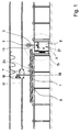
- FIG. 1 shows a joinery machine which has a support 8 for a workpiece 1, which can be moved in the longitudinal direction of the support 8 by means of a transport device 7.
- the transport device consists of a motor-driven towing device 18, which is connected to the workpiece 1 via a stamp 19.
- a processing unit 6 arranged which has a support frame 15 with a tool spindle 5 which can be displaced in the vertical and in the horizontal direction.
- the support 8 consists of a plurality of guide rollers 20 which are arranged one behind the other in the longitudinal direction of the support 8 and on which the workpiece 1 rolls during the movement through the joinery machine.
- a recess 21 is provided which receives the processing unit 6.
- This recess 21 is formed, for example, by a corresponding distance between the guide rollers 20.
- the support 8 can consist of a conveyor belt interrupted in the area of the processing units 6 or a sliding plane with a corresponding recess for the passage of the tool spindle 5.
- the support frame 15 is displaced by means of the adjusting means customary in machine and plant construction, such as hydraulic cylinders or motors, which can be controlled by a machine control.
- This machine control can be a conventional control as well as a computer-aided control (CNC control).
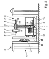
- a turntable 4 is mounted with a base 3, on which the tool spindle 5 is arranged with a tool 2. Further details of the processing unit 6 result from FIG. 2, in which the detail X in FIG. 1 is shown enlarged.
- the processing unit 6 is in a rest position shown.
- the support frame 15 is moved to the lowest position, so that the tool spindle 5 with the tools 2 ', 2''and2''' is arranged below the plane of the support 8.
- the turntable 4 is rotatably mounted on which the base 3 is fastened.
- the drive motor 12 for the spindle drive of the tool spindle 5 is arranged on the turntable 4.
- the drive force is transmitted via a belt drive, for example a toothed or V-belt 22, to the tool spindle 5 arranged in the upper region of the base 3.
- the turntable 4 itself can be driven by an actuator 9, which is also arranged in the support frame 15.
- the turntable 4 can consist, for example, of a pulley which is rotated by the servomotor 9 via a V-belt depending on the system control.
- the turntable 4 can also consist of a gear wheel which is driven by a pinion driven by the servomotor 9.
- the tool spindle 5 Due to the arrangement of the tool spindle 5 in the upper region of the base 3, which can be rotated with the rotary plate 4, it can be rotated about the axis of rotation D.
- the tool spindle 5 is supported with its central region via two roller bearings in the upper end region of the base 3 and has a radial milling cutter 2 'and a face milling cutter 2' 'on its ends projecting on both sides of the pedestal 3.
- the radial milling cutter 2 'additionally has on its side used for mounting the tool spindle an end mill 2' '' with which smaller grooves or cylindrical recesses can be produced.
- Fig. 2 it is indicated that several tools 2 are used on the tool spindle.
- the left one of the tool spindle initially carries a radial milling cutter 3 with a correspondingly large diameter and a finger milling cutter 2 '''is arranged on its left extension of the tool spindle, whereby the flexibility of the joinery system according to the invention is increased.
- the ends of the tool spindle 5 have chucks 10, 11.
- the drive motor 12 can also be arranged in the end region of the base 3.
- the power transmission to the tool spindle 5 can be simplified, but the relatively heavy motor 12 causes undesirable vibrations of the base, so that it must be reinforced accordingly.
- tool spindles 5 can also be arranged on the base 3, which are either driven by a motor via a corresponding gear, or can be driven by several motors.
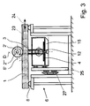
- FIG. 3 shows the processing unit 6 from FIG. 2 during the processing of a beam-shaped wooden workpiece 1.
- a radial milling cutter 2 'driven by the tool spindle 5 is working a longitudinal groove into the top of the workpiece 1.
- the support frame 15 has been moved vertically upwards and transversely to the support 8, so that the radial milling cutter 2 'has assumed the required position.
- the tool spindle 5 was rotated through 90 ° about the axis of rotation D in order to align the tool 2 ′ for milling the longitudinal groove 23.
- the radial milling cutter 2 ′ works the groove 23 into the workpiece 1.
- the transport device 7 is able to guide the workpiece 1 so precisely that the desired manufacturing accuracy is achieved.
- the feed movement of the transport device 7 is identified by the double arrow 24.
- the transport device 7 embosses a movement in both directions, forwards, on the wooden workpiece and backwards, one.
- the workpiece 1 is moved in the forward direction of the joinery machine. After this processing has been completed, further processing can then be carried out by changing the direction of the workpiece movement and by possibly rotating or transversely displacing the tool spindle 5.
- the support frame 15 is guided vertically on a guide tree 25.
- the drive means necessary for this are not shown for the sake of clarity.
- the guide tree 25 is slidably arranged for horizontal movement.
- the guide tree 25 is mounted on slide bearings 26.
- the guide tree 25 is provided, for example, on both sides of the support frame 15.
- a guide 27 is provided for movement in the horizontal direction. Such a configuration achieves a movement of the support frame in a plane which is here perpendicular to the plane of the drawing. A different configuration can be selected by a corresponding configuration of the guide 27.
- the definition of the spindle axis 5 ' also includes the axis about which the tool 2 rotates.
Landscapes
- Engineering & Computer Science (AREA)
- Mechanical Engineering (AREA)
- Life Sciences & Earth Sciences (AREA)
- Wood Science & Technology (AREA)
- Forests & Forestry (AREA)
- Milling, Drilling, And Turning Of Wood (AREA)
- Treatment Of Steel In Its Molten State (AREA)
- Compositions Of Macromolecular Compounds (AREA)
- Saccharide Compounds (AREA)
- Turning (AREA)
- Pressure Welding/Diffusion-Bonding (AREA)
- Drilling And Boring (AREA)
Abstract
Description
Die Erfindung betrifft eine Abbundanlage zur Bearbeitung von Strangmaterial, insbesondere zur Bearbeitung von stangenförmigen Holzwerkstücken, Holzbalken, Brettern und dergleichen, welche auf einer Auflage aufliegen und von einer Transporteinrichtung transportiert werden, wenigstens einem, entlang der Transporteinrichtung angeordneten Bearbeitungsaggregat mit einer von einem Spindelantrieb angetriebenen Werkzeugspindel, welche in einer Ebene verschiebbar ist und an der ein Werkzeug für die Bearbeitung des Werkstückes angeordnet ist.The invention relates to a joinery machine for processing strand material, in particular for processing rod-shaped wooden workpieces, wooden beams, boards and the like, which rest on a support and are transported by a transport device, at least one processing unit arranged along the transport device with a tool spindle driven by a spindle drive , which is displaceable in one plane and on which a tool for machining the workpiece is arranged.
Eine Abbundanlage dieser Art ist aus der DE-OS 42 08 233 bekannt. Die dort beschriebene Abbundanlage weist eine langgezogene Auflage für das Werkstück und eine Transporteinrichtung auf, mit der das Werkstück entlang der Auflage transportiert werden kann. Die Transporteinrichtung weist einen Mitnehmer auf, der mit dem Werkstück verbindbar ist und, motorisch entlang einer parallel zur Auflage verlaufenden Führungsschiene getrieben, das Werkstück durch die Abbundanlage hindurch zieht.A joinery machine of this type is known from DE-OS 42 08 233. The joinery machine described there has an elongated support for the workpiece and a transport device with which the workpiece can be transported along the support. The transport device has a driver which can be connected to the workpiece and, driven by a motor along a guide rail running parallel to the support, pulls the workpiece through the joinery machine.
Die vorbeschriebenen Abbundanlagen werden dazu verwendet die aufwendige Handarbeit eines Zimmermannes maschinell zu unterstützen. Hierbei ist die Abbundanlage mit einer Computersteuerung verbunden, die die Daten eines Konstruktionsprogrammes übernimmt und aus diesen Daten die entsprechenden Bearbeitungsschritte für die Erstellung eines entsprechenden Holzwerkstückes für ein Dachstuhl oder ein sonstiges Holzbauwerk ermittelt. Hierzu weißt die Abbundanlage eine Vielzahl von verschiedenen Bearbeitungsaggregaten auf, die entsprechend der Vorgaben der Steuerung nach dem Konstruktionsplan eingesetzt werden. Durch die exakte Führung des Holzstückes durch die Transporteinrichtung wird eine exakte Bearbeitung erreicht.The joinery systems described above are used to mechanically support the elaborate manual work of a carpenter. Here, the joinery system is connected to a computer control, which takes over the data from a construction program and uses this data to determine the corresponding processing steps for the creation of a corresponding wooden workpiece for a roof structure or other wooden structure. For this purpose, the joinery machine has a variety of different processing units that are used according to the specifications of the control system according to the construction plan. Exact processing is achieved by the exact guidance of the piece of wood through the transport device.
Der Vorteil der bekannten Abbundanlage liegt darin, daß die vormals aufwendige Handarbeit durch den Zimmermann nun vollständig automatisiert erfolgt. Dieser Effekt wird durch den zunehmenden Einsatz von Computern in der Konstruktion der Dachstühle weiter verstärkt, da automatisierte Abbundanlagen über eine CNC-Steuerung die Daten für die Bearbeitung der Werkstücke direkt aus dem Computer des Konstrukteurs des Dachstuhls übernehmen. Eine derartige CNC-gesteuerte Abbundanlage ist aus der DE-PS 34 20 080 bekannt.The advantage of the known joinery machine is that the previously complex manual work is now fully automated by the carpenter. This effect is further intensified by the increasing use of computers in the construction of the roof trusses, since automated joinery systems take over the data for the processing of the workpieces directly from the computer of the designer of the roof truss via a CNC control. Such a CNC-controlled joinery machine is known from DE-PS 34 20 080.
Neben der Erstellung von Dachstühlen sind aber auch andere Abbundarbeiten zum Beispiel die Herstellung von Fertighäusern usw. mit den vorbeschriebenen Abbundanlagen möglich.In addition to the construction of roof trusses, other joinery work is also possible, for example the manufacture of prefabricated houses, etc. using the joinery systems described above.
Im Verlaufe das Transportes durch die Anlage passiert das Werkstück zumindest ein, in der Regel jedoch mehrere verschiedene Bearbeitungsaggregate, die das Werkstück durch die üblichen Verfahren wie zum Beispiel Fräsen, Bohren oder Sägen bearbeiten. Dabei werden an dem Werkstück sowohl Längsbearbeitungen, wie das Einbringen von Längsnuten, das Abfasen von Kanten oder dergleichen, als auch Querbearbeitungen wie zum Beispiel das Ablängen unter einem bestimmten Winkel oder das Einbringen von Quernuten oder Bohrungen für Zapfen usw. vorgenommen. Zur Durchführung dieser verschiedenen Bearbeitungsschritte sind unterschiedlichste Werkzeuge, wie zum Beispiel Stirn- und Radialfräser, runde und kantige Radialfräser, verschiedene Bohrer oder Sägen erforderlich.In the course of the transport through the system, the workpiece passes through at least one, but usually several different processing units, which process the workpiece by the usual methods such as milling, drilling or sawing. Longitudinal machining, such as the introduction of longitudinal grooves, chamfering edges or the like, as well as transverse machining, such as cutting to a certain angle or the introduction of transverse grooves or bores for pins, etc., are carried out on the workpiece. A wide variety of tools are required to carry out these various machining steps, such as face and radial milling cutters, round and angular radial milling cutters, various drills or saws.
Nachteilig ist bei den gattungsgemäßen Abbundanlagen jedoch, daß für die verschiedenen, an dem jeweiligen Werkstück vorzunehmenden Bearbeitungsschritte entweder jeweils gesonderte, hintereinander angeordnete Bearbeitungsaggregate vorgesehen werden müssen oder, wenn bereits ein geeignetes Bearbeitungsaggregat in der Anlage vorhanden ist, nach der ersten Bearbeitung das Werkzeug gewechselt und das Werkstück nochmals für eine weitere Bearbeitung durch die Anlage geschickt werden muß. Dieser Nachteil tritt nicht nur dann auf, wenn verschiedene Bearbeitungsschritte an einem Werkstück erforderlich sind, sondern auch dann, wenn mehrere Werkstücke hintereinander zu bearbeiten sind, wobei an den verschiedenen Werkstücken jeweils verschiedene Bearbeitungen vorgenommen werden sollen.A disadvantage of the generic joinery systems, however, is that separate processing units arranged one behind the other must either be provided for the various processing steps to be carried out on the respective workpiece or, if a suitable processing unit is already present in the system, the tool is changed after the first processing and the workpiece must be sent through the system again for further processing. This disadvantage arises not only when different machining steps on a workpiece are required, but also when several workpieces are to be machined one after the other, with different machining operations being to be carried out on the different workpieces.
Durch den Wechsel der Werkzeuge wird der Durchsatz der Abbundanlagen jedoch erheblich verringert, da der kontinuierliche Bearbeitungsprozeß jeweils unterbrochen werden muß, um das Werkstück erneut der Anlage zuzuführen. Weiterhin fallen Rüstzeiten an, die die Bearbeitungszeiten zusätzlich erhöhen.By changing the tools, however, the throughput of the joinery systems is considerably reduced, since the continuous machining process must be interrupted in order to feed the workpiece to the system again. Set-up times are also incurred, which further increase processing times.
Die Verwendung zusätzlicher Bearbeitungsaggregate führt dazu, daß die Abbundanlage zum einen aufwendiger wird und damit die Herstellungskosten der Anlage steigen, da für jedes Bearbeitungsaggregat eine entsprechende Beweglichkeit vorgesehen werden muß, die entsprechende Antriebsmittel benötigen. Zum anderen nimmt der für die Aufstellung der Anlage notwendige Raumbedarf mit jedem weiteren Bearbeitungsaggregat zu. Der zusätzliche Raumbedarf, zum Beispiel in einer Halle, einer derartigen Anlage ist beachtlich, da die Anlagen aufgrund der Länge der mit ihr zu bearbeitenden Werkstücke bereits verhältnismäßig groß sind. So muß zum Beispiel bei Anlagen zur Bearbeitung von Dachsparren alleine für die Zuführung und die Entnahme der Werkstücke, die in der Regel eine Länge von bis zu 10 m haben, eine Länge der Abbundanlage von mehr als 20 m vorgesehen werden.The use of additional processing units leads to the fact that the joinery system becomes more complex on the one hand and thus the manufacturing costs of the system increase, since a corresponding mobility must be provided for each processing unit, which require the corresponding drive means. On the other hand, the space required to set up the system increases with each additional processing unit. The additional space required, for example in a hall, of such a system is considerable since the systems are already relatively large due to the length of the workpieces to be machined with them. For example, in systems for processing rafters, a length of the joinery system of more than 20 m must be provided for the feeding and removal of the workpieces, which generally have a length of up to 10 m.
Aufgabe der Erfindung ist es daher, eine kostengünstig herzustellende Abbundanlage zu schaffen, auf der Strangmaterial wie vorbeschrieben mit mehreren Werkzeugen bei möglichst geringem Raumbedarf der Abbundanlage bearbeitet werden.It is therefore an object of the invention to provide a joinery system which can be produced inexpensively, on which strand material, as described above, is processed with a number of tools while the space requirement of the joinery system is as small as possible.
Diese Aufgabe wird nach der Erfindung dadurch gelöst, daß die Werkzeugspindel einer Abbundanlage der eingangs genannten Art um eine zur Spindelachse senkrechte Drehachse drehbar ist und der Spindelantrieb eine Mehrzahl von Werkzeugen antreibt.This object is achieved according to the invention in that the tool spindle of a joinery machine of the type mentioned at the outset is rotatable about an axis of rotation perpendicular to the spindle axis and the spindle drive drives a plurality of tools.
Durch die erfindungsgemäße Ausgestaltung der Abbundanlage ist es nun möglich, an der Werkzeugspindel eines Bearbeitungsaggregates mehrere, unabhängig voneinander einsetzbare Werkzeuge anzuordnen. Hierdurch kann die Anzahl der benötigten Bearbeitungsaggregate deutlich reduziert werde, wodurch sich die Baugröße der Anlage ebenfalls verringert. Indem die Position der Werkzeugspindel relativ zum Werkstück beliebig veränderlich ist, kann auf einer Spindel ein großes Spektrum unterschiedlichster Werkzeuge angeordnet werden.The inventive configuration of the joinery machine makes it possible to arrange several tools that can be used independently of one another on the tool spindle of a processing unit. As a result, the number of processing units required can be significantly reduced, which also reduces the size of the system. Because the position of the tool spindle relative to the workpiece can be changed as required, a large spectrum of different tools can be arranged on a spindle.
So kann zum Beispiel bei einer Ausführungsform der Erfindung die Werkzeugspindel in ihrem mittleren Bereich gelagert sein, so daß sie zwei aus der Lagerung herausstehende freie Enden aufweist, die mit Werkzeugen bestückbar sind. An einem Ende der Spindel kann beispielsweise ein Stirnfräser angeordnet sein, mit dem einerseits die Stirnseite des Werkstückes bearbeitbar ist, als auch, bei um 90° gedrehter Werkzeugspindel und entsprechend in der Ebene quer zum Werkstück verfahrenem Bearbeitungsaggregat, die Seiten des Werkstückes bearbeitbar sind. An dem anderen, gegenüberliegenden Ende der Spindel ist zum Beispiel ein weiteres Werkzeug angeordnet, mit dem andere Bearbeitungsschritte durchgeführt werden.For example, in one embodiment of the invention, the tool spindle can be mounted in its central region, so that it has two free ends protruding from the mounting, which can be equipped with tools. At one end of the spindle, for example, an end mill can be arranged, with which the end face of the workpiece can be machined on the one hand, and, with the tool spindle rotated through 90 ° and correspondingly in the plane transverse to the workpiece, the sides of the workpiece can be machined. At the other, opposite end of the spindle, for example, another tool is arranged, with which other processing steps are carried out.
Bei einer besonders vorteilhaften Ausgestaltung der Erfindung sind an der Werkzeugspindel mehrere Werkzeuge angeordnet. Diese sind aufgrund der durch die Erfindung hinzugewonnenen Flexibilität der Abbundanlage vielseitig einsetzbar. So kann zum Beispiel ein Radialfräser mit relativ großem Außendurchmesser verwendet werden, an dessen Seite, der Spindellagerung abgewandt, ein kleiner Fingerfräser als Stirnfräser angeordnet ist. Mit einer derartigen Werkzeugkombination lassen sich sowohl Nuten durch den Radialfräser, als auch Ausnehmungen durch den Stirnfräser herstellen. Hierzu fährt das Bearbeitungsaggregat lediglich die erforderliche Position an, indem es die Drehachse der Werkzeugspindel durch Transversalbewegungen der Bearbeitungsaggregates entsprechend positioniert und das benötigte Werkzeug durch Drehung der Werkzeugspindel um die zur Spindel senkrechte Achse in Bearbeitungsposition bringt.In a particularly advantageous embodiment of the invention, several tools are arranged on the tool spindle. These are versatile due to the flexibility of the joinery system gained by the invention. For example, a radial milling cutter with a relatively large outside diameter can be used, on the side of which, facing away from the spindle bearing, a small end mill is arranged as a face milling cutter. With a tool combination of this type, grooves can be produced by the radial milling cutter as well as recesses by the face milling cutter. For this purpose, the processing unit only moves to the required position by positioning the axis of rotation of the tool spindle accordingly by transversely moving the processing unit and bringing the required tool into the processing position by rotating the tool spindle about the axis perpendicular to the spindle.
Die Werkzeuge sind hierbei zum Beispiel auf einer Seite der Werkzeugspindel hintereinander angeordnet. Es ist aber auch möglich, daß die Werkzeugspindel einen zentral in der Mitte angeordneten Antrieb aufweist, und die beiden Enden der Werkzeugspindel ein oder mehrere Werkzeuge tragen.The tools are arranged one behind the other on one side of the tool spindle, for example. However, it is also possible for the tool spindle to have a drive arranged centrally in the middle, and for the two ends of the tool spindle to carry one or more tools.
Bei einer weiteren Ausgestaltung der Erfindung ist es weiter vorteilhaft, an den beiden freien Enden der Werkzeugspindel mehrere Werkzeuge im Abstand zueinander anzuordnen, so daß durch ein Bearbeitungsaggregat noch mehr Werkzeuge gehandhabt werden kann. Dabei können zum Beispiel so mehrere Radialfräser nebeneinander angeordnet werden. Hierdurch können entweder zwei zueinander parallele Nuten in einem Arbeitsgang gefräst werden, oder, falls der Abstand der beiden Radialfräser größer ist als die Breite des zu bearbeitenden Werkstückes, verschiedene Nutformen hergestellt werden.In a further embodiment of the invention, it is further advantageous to arrange a plurality of tools at a distance from one another at the two free ends of the tool spindle, so that even more tools can be handled by one processing unit. In this way, for example, several radial milling cutters can be arranged side by side. As a result, either two mutually parallel grooves can be milled in one operation or, if the distance between the two radial milling cutters is greater than the width of the workpiece to be machined, different groove shapes can be produced.
Zur Herstellung einer Rechtecknut kann so ein kantiger Fräser vorgesehen sein, während ein abgerundeter, im Abstand neben diesem angeordneter Radialfräser eine innenrunde Nut herzustellen vermag. Zum Wechsel zwischen beiden Nutformen wird die rechtwinklig zum Werkstück angeordnete Werkzeugspindel einfach um eine entsprechende Strecke quer zum Werkstück bewegt. Je nach Querabmessung des Bearbeitungsaggregats und Beschaffenheit der Werkstückauflage können so nahezu beliebig viele Fräser und Sägeblätter nebeneinander angeordnet werden.An angular milling cutter can thus be provided for producing a rectangular groove, while a rounded radial milling cutter arranged at a distance next to this can produce an internal circular groove. To switch between the two groove shapes, the tool spindle, which is arranged at right angles to the workpiece, is simply moved a corresponding distance across the workpiece. Depending on the transverse dimensions of the processing unit and the nature of the workpiece support, almost any number of milling cutters and saw blades can be arranged side by side.
In einer weiteren Ausgestaltung der Erfindung ist vorgesehen, daß am äußeren Ende der Werkzeugspindel ein Stirn- oder Fingerfräser angeordnet ist. Dieser Stirn- oder Fingerfräser ist zusammen zum Beispiel mit einem Radialfräser mit entsprechend großem Durchmesser kombiniert. Dieser Radialfräser weist zum Beispiel eine Länge von ungefähr 10 cm und einem Durchmesser von bis zu 40 cm auf. Durch die Kombination eines großen und eines verhältnismäßig kleinen Fräsers wird die Flexibilität der Abbundanlage wesentlich erhöht. Die Anordnung des äußeren Fingerfräsers dient zum Beispiel für die feine Bearbeitung von Oberflächen zum Beispiel als Oberfräse. Anstelle des Stirn- oder Fingerfräsers ist auch die Verwendung eines Bohrers möglich.In a further embodiment of the invention it is provided that an end mill or end mill is arranged at the outer end of the tool spindle. This end mill or end mill is combined, for example, with a radial mill with a correspondingly large diameter. This radial milling cutter has, for example, a length of approximately 10 cm and a diameter of up to 40 cm. The combination of a large and a relatively small milling cutter increases the flexibility of the joinery system considerably. The arrangement of the outer end mill is used, for example, for fine machining of surfaces, for example as a router. Instead of the end mill or end mill, it is also possible to use a drill.
Desweiteren ist es günstig, wenn die Werkzeugspindel im Endbereich eines Standfusses gelagert ist und das gegenüberliegende Ende des Standfusses auf einem drehbar gelagerten Drehteller befestigt ist, der von einem Stellmotor angetrieben ist, wobei der Drehteller in der im wesentlichen vertikal orientierten Ebene verschiebbar ist.Furthermore, it is advantageous if the tool spindle is mounted in the end region of a pedestal and the opposite end of the pedestal is fastened to a rotatably mounted turntable which is driven by an actuator, the turntable being displaceable in the essentially vertically oriented plane.
Die Vielseitigkeit der erfindungsgemäßen Abbundanlage begründet sich aus der Verschiebbarkeit der Werkzeugspindel in einer Ebene, die zur Vorschubrichtung abgewinkelt ist und der Drehbarkeit der Werkzeugspindel um eine zur Spindelachse senkrechte Drehachse. Idealerweise ist die Ebene, in der die Werkzeugspindel verschiebbar ist, rechtwinklig zur Vorschubrichtung angeordnet. Bei horizontalem Vorschub kann die Werkzeugspindel dann durch eine Querbewegung rechtwinklig zur Vorschubrichtung und eine Vertikalbewegung in jede gewünschte Position verfahren werden. Hierzu ist die Spindel zusammen mit dem Spindelantrieb auf einem drehbaren Standfuß angeordnet, der auf einem Traggestell gelagert ist, das in der im wesentlichen vertikal orientierten Ebene verschiebbar ist.The versatility of the joinery system according to the invention is based on the displaceability of the tool spindle in a plane which is angled to the feed direction and the rotatability of the tool spindle about an axis of rotation perpendicular to the spindle axis. Ideally, the plane in which the tool spindle can be moved is arranged at right angles to the feed direction. With horizontal feed, the tool spindle can then be moved to any desired position by a transverse movement perpendicular to the feed direction and a vertical movement. For this purpose, the spindle, together with the spindle drive, is arranged on a rotatable pedestal which is mounted on a support frame which can be displaced in the essentially vertically oriented plane.
Bei einer weiteren vorteilhaften Ausgestaltung kann der Standfuß mit dem Spindelantrieb und der Werkzeugspindel aber auch auf einem Trägerelement angeordnet sein, das auf einer kreis- oder elipsenförmigen Bahn um das Werkstück herum verfahrbar ist. Hierzu kann die Transporteinrichtung und die Auflage für das Werkstück von einer kreis- oder elipsenförmigen Führungsschiene, beispielsweise einer gerundeten Zahnstange, umschlossen sein, auf der das motorisch angetriebene Trägerelement beweglich ist. Um die Werkzeugspindel bei dieser Ausführungsform in die gewünschten Positionen verfahren zu können, ist hier zusätzlich erforderlich, daß der Abstand zwischen der Werkzeugspindel und dem Trägerelement durch die Anlagensteuerung veränderlich ist. So kann der Standfuß zum Beispiel als Teleskopstange ausgebildet sein, wobei der Spindelantrieb entweder jenseits des Verstellbereiches in der Nähe der Werkzeugspindel angeordnet ist oder eine ebenfalls längenverstellbare Kraftübertragung aufweist. Diese kann beispielsweise aus einem Riementrieb mit geeigneter Spannvorrichtung bestehen.In a further advantageous embodiment, the base with the spindle drive and the tool spindle can also be arranged on a carrier element which can be moved around the workpiece in a circular or elliptical path. For this purpose, the transport device and the support for the workpiece can be enclosed by a circular or elliptical guide rail, for example a rounded toothed rack, on which the motor-driven carrier element can be moved. In order to be able to move the tool spindle into the desired positions in this embodiment, it is additionally necessary here that the distance between the tool spindle and the carrier element can be varied by the system control. For example, the base can be designed as a telescopic rod, with the spindle drive is either arranged beyond the adjustment range in the vicinity of the tool spindle or has a length-adjustable power transmission. This can consist, for example, of a belt drive with a suitable tensioning device.
Bei dieser Ausführungsform wird die Werkzeugspindel nun zunächst durch Anfahren einer bestimmten Winkelposition des Trägerelementes und anschließendes Positionieren in radialer Richtung in die gewünschte Position gebracht. Selbstverständlich kann hierzu die Führungsschiene auch in Form eines Kreis- oder Elipsenausschnittes, ohne die Transportvorrichtung und die Auflage vollständig zu umschließen, ausgebildet sein. Erforderlich ist lediglich eine ausreichende Beweglichkeit des Trägerelementes auf der entsprechenden Kreisbahn.In this embodiment, the tool spindle is first brought into the desired position by moving to a specific angular position of the carrier element and then positioning it in the radial direction. Of course, the guide rail can also be designed in the form of a circular or elliptical cutout without completely enclosing the transport device and the support. All that is required is sufficient mobility of the carrier element on the corresponding circular path.
Hierbei ist es günstig, wenn die Werkzeugspindel relativ zum Trägerelement in Richtung des Werkstückes verschiebbar ist. Durch eine solche Beweglichkeit wird eine optimale Anpassung der Antriebsspindel an das Werkstück erreicht.It is advantageous if the tool spindle can be displaced relative to the carrier element in the direction of the workpiece. Such flexibility enables the drive spindle to be optimally adapted to the workpiece.
Der Vorschub der erfindungsgemäßen Abbundanlage kann sowohl durch eine Bewegung des Bearbeitungsaggregates, als auch durch die Werkstückbewegung oder einer Kombination aus beiden Bewegungen vollzogen werden.The joinery machine according to the invention can be advanced by a movement of the processing unit as well as by the movement of the workpiece or a combination of both movements.
Besonders vorteilhaft ist es, wenn der Vorschub durch die Transporteinrichtung, also durch die Bewegung des Werkstückes durch die Anlage vollzogen wird, da hierdurch die raumaufwendige Verfahrbarkeit des Bearbeitungsaggregates in Vorschubrichtung entfällt und die einzelnen Bearbeitungsaggregate mit geringerem Abstand zueinander angeordnet sind. Hierbei weist eine weitere vorteilhafte Ausgestaltung der Erfindung eine Kopplung des Werkstückes mit der Transporteinrichtung auf, die es gewährleistet, das Werkstück sowohl vorwärts in Hauptvorschubrichtung, als auch rückwärts in die entgegengesetzte Richtung zu bewegen. Hierdurch kann das Werkstück mehrfach ein Bearbeitungsaggregat passieren und in Kombination mit der Vielzahl der an diesem Bearbeitungsaggregat nun vielseitig einsetzbaren Werkzeugen auf verschiedenste Weise bearbeitet werden. Dabei kann die Bearbeitung in beiden Bewegungsrichtungen erfolgen.It is particularly advantageous if the feed is carried out by the transport device, that is to say by the movement of the workpiece through the system, since this eliminates the space-consuming travel of the machining unit in the feed direction and the individual machining units are arranged at a smaller distance from one another. Here, a further advantageous embodiment of the invention has a coupling of the workpiece to the transport device, which ensures that the workpiece is moved both forward in the main feed direction, as well as moving backwards in the opposite direction. As a result, the workpiece can pass through a processing unit several times and, in combination with the large number of tools that can now be used in a variety of ways on this processing unit, can be processed in a wide variety of ways. The processing can take place in both directions of movement.
Schließlich kann der Vorschub aber auch durch eine Kombination aus Bewegung des Werkstückes und Bewegung des Bearbeitungsaggregates realisiert werden. Dies hat zwar eine aufwendigere Konstruktion des Bearbeitungsaggregates zur Folge, durch die wesentlich schnellere und weniger träge Relativgeschwindigkeit, die nun als nutzbare Vorschubgeschwindigkeit zur Verfügung steht, läßt sich die Bearbeitung jedoch erheblich beschleunigen.Finally, the feed can also be realized by a combination of movement of the workpiece and movement of the processing unit. Although this results in a more complex construction of the processing unit, the processing can be considerably accelerated by the considerably faster and less sluggish relative speed, which is now available as a usable feed rate.
In einer bevorzugten Ausgestaltung der Erfindung ist vorgesehen, daß der Spindelantrieb auf eine Mehrzahl von Werkzeugspindeln wirkt. Zum Beispiel ist vorgesehen, daß zwei Werkzeugspindeln in einem rechten Winkel zueinander angeordnet sind und jede Werkzeugspindel ein oder mehrere Werkzeuge trägt. Bei einer entsprechenden konstruktiven Auslegung ist somit eine sehr große Flexibilität des Bearbeitungsaggregates möglich, da auf den verschiedenen Spindelhälften unterschiedlichste Werkzeuge anordbar sind und somit ein breites Spektrum an Bearbeitungen ausführbar sind.In a preferred embodiment of the invention it is provided that the spindle drive acts on a plurality of tool spindles. For example, it is provided that two tool spindles are arranged at right angles to each other and each tool spindle carries one or more tools. With a corresponding constructive design, a very high flexibility of the processing unit is possible, since a wide variety of tools can be arranged on the different spindle halves and thus a wide range of processing can be carried out.
Auch ist es günstig, wenn der Abstand zwischen dem Standfuß und dem ihm zugewandten Ende des Futters größer ist als die halbe Maximalbreite des zu bearbeitenden Werkstückes. Durch eine solche Ausgestaltung wird erreicht, daß ein Werkstück mit bekannter Maximalbreite optimal bearbeitet wird, das heißt insbesondere eine Bearbeitung über die ganze Breite des Werkstückes erfolgt. Hierzu ist dann zum Beispiel ein zweimaliges Anfahren der Werkzeugspindel an das Werkstück notwendig, wobei das Anfahren dann von zwei gegenüberliegenden Positionen aus erfolgt. Dadurch erreicht die Erfindung eine optimale Einsetzbarkeit bei entsprechend angepaßter Konstruktion.It is also advantageous if the distance between the base and the end of the chuck facing it is greater than half the maximum width of the workpiece to be machined. Such a configuration ensures that a workpiece with a known maximum width is optimally machined, that is to say in particular machining is carried out over the entire width of the workpiece. For example, there is a double It is necessary to approach the tool spindle to the workpiece, the approach then taking place from two opposite positions. As a result, the invention achieves optimal usability with a correspondingly adapted construction.
Auch ist vorgesehen, daß das Bearbeitungsaggregat einen Hub ausführen kann, der derart bemessen ist, daß eine maximale Höhe des Werkstückes mit den Fräsers bearbeitbar ist, wobei das Bearbeitungsaggregat, insbesondere die Werkzeugspindel soweit absenkbar ist, daß eine Bearbeitung des Werkstückes durch Werkzeuge nicht erfolgt.It is also provided that the machining unit can execute a stroke which is dimensioned such that a maximum height of the workpiece can be machined with the milling cutter, the machining unit, in particular the tool spindle, being able to be lowered to such an extent that the workpiece is not machined by tools.
Es ist günstig, wenn die Werkzeugspindel über einen Riemen- oder Kettenantrieb von einem auf dem Drehteller befestigten Antriebsmotor angetrieben ist. Durch eine solche Ausgestaltung wird ein vibrationsarmer Antrieb geschaffen. Auf der anderen Seite ist es auch möglich, den Antriebsmotor auf der Antriebsspindel vorzusehen. Für eine optimale Beweglichkeit des Bearbeitungsaggregates ist es hierbei günstig, daß der Antriebsmotor auf dem Drehteller befestigt ist.It is advantageous if the tool spindle is driven by a drive motor attached to the turntable via a belt or chain drive. Such a configuration creates a low-vibration drive. On the other hand, it is also possible to provide the drive motor on the drive spindle. For optimum mobility of the processing unit, it is advantageous that the drive motor is attached to the turntable.
Auch ist es günstig, daß ein Wechselmagazin vorgesehen ist, und die Werkzeugspindel zur automatischen Bestückung mit Bearbeitungswerkzeugen an das Wechselmagazin heranfahrbar ist. In einem Wechselmagazin sind zum Beispiel Ersatzwerkzeuge oder Werkzeuge für unterschiedliche Einsatzzwecke vorgehalten. Durch eine solche Ausgestaltung können Rüstzeiten reduziert werden.It is also favorable that an interchangeable magazine is provided and the tool spindle can be moved up to the interchangeable magazine for automatic loading with processing tools. For example, replacement tools or tools for various purposes are kept in a change magazine. Set-up times can be reduced by such a configuration.
Auch ist es günstig, daß das Bearbeitungsaggregat im wesentlichen unterhalb der Transporteinrichtung angeordnet ist und die Auflage im Bereich des Bearbeitungsaggregates eine Ausnehmung für die Werkzeugspindel aufweist. Durch eine solche Ausgestaltung ist eine platzsparende Anordnung des Bearbeitungsaggregates möglich. Es ist auch möglich, daß das Bearbeitungsaggregat seitlich neben der Transporteinrichtung, und bei entsprechender Ausgestaltung der Transporteinrichtung auch oberhalb der Auflage angeordnet ist.It is also favorable that the processing unit is arranged substantially below the transport device and the support in the area of the processing unit has a recess for the tool spindle. Such a configuration enables a space-saving arrangement of the processing unit. It is also possible that Processing unit is arranged laterally next to the transport device, and with a corresponding design of the transport device also above the support.
In einer weiteren Ausgestaltung der Erfindung ist vorgesehen, daß die Werkzeugspindel um eine zweite, zur Drehachse und zur Werkzeugspindel rechtwinkligen Drehachse drehbar ist. Durch eine solche Ausgestaltung wird die Flexibilität der Abbundanlage weiter erhöht, da entsprechend schwierig angeordnete Bearbeitungen ausführbar sind.In a further embodiment of the invention it is provided that the tool spindle can be rotated about a second axis of rotation that is perpendicular to the axis of rotation and to the tool spindle. Such a configuration further increases the flexibility of the joinery system, since correspondingly difficult machining operations can be carried out.
In der Zeichnung ist die Erfindung schematisch dargestellt. Es zeigen:
- Fig. 1
- eine Seitenansicht einer erfindungsgemäßen Abbundanlage,
- Fig. 2
- eine Seitenansicht eines Bearbeitungsaggregats einer erfindungsgemäßen Abbundanlage (Einzelheit X in Fig. 1) und in
- Fig. 3
- eine Seitenansicht auf das Bearbeitungsaggregat nach Fig. 2, während der Bearbeitung eines Werkstückes.
- Fig. 1
- a side view of a joinery machine according to the invention,
- Fig. 2
- a side view of a processing unit of a joinery system according to the invention (detail X in Fig. 1) and in
- Fig. 3
- a side view of the processing unit of FIG. 2, while processing a workpiece.
In Figur 1 ist eine Abbundanlage dargestellt, die eine Auflage 8 für ein Werkstück 1 aufweist, das mittels einer Transporteinrichtung 7 in Längsrichtung der Auflage 8 bewegt werden kann. Die Transporteinrichtung besteht aus einer motorisch entlang einer Führungsbahn 17 getriebenen Schleppeinrichtung 18, die über einen Stempel 19 mit dem Werkstück 1 verbunden ist. Unterhalb der Auflage 8 für das Werkstück 1 ist ein Bearbeitungsaggregat 6 angeordnet, das ein in vertikaler sowie in horizontaler Richtung verschiebbares Traggestell 15 mit einer Werkzeugspindel 5 aufweist.1 shows a joinery machine which has a
Die Auflage 8 besteht aus einer Vielzahl von Führungsrollen 20, die in Längsrichtung der Auflage 8 hintereinander angeordnet sind und auf denen das Werkstück 1 während der Bewegung durch die Abbundanlage abrollt.The
In der Auflage 8 ist eine Aussparung 21 vorgesehen, welche das Bearbeitungsaggregat 6 aufnimmt. Diese Aussparung 21 wird zum Beispiel durch einen entsprechenden Abstand der Führungsrollen 20 gebildet.In the
Auch andere Ausgestaltungen der Auflage 8 sind möglich. So kann die Auflage 8 zum Beispiel aus einem im Bereich der Bearbeitungsaggregate 6 unterbrochenem Transportband oder einer Gleitebene mit entsprechender Ausnehmung für den Durchlass des Werkzeugspindel 5 bestehen.Other configurations of the
Die Verschiebung des Traggestells 15 erfolgt über die im Maschinen- und Anlagenbau üblichen Stellmittel, wie zum Beispiel Hydraulikzylinder oder Motoren, die über eine Maschinensteuerung ansteuerbar sind. Bei dieser Maschinensteuerung kann es sich sowohl um eine herkömmliche Steuerung als auch um eine computergestützte Steuerung (CNC-Steuerung) handeln.The
Auf dem Traggestell 15 ist ein Drehteller 4 mit einen Standfuß 3 gelagert, auf dem die Werkzeugspindel 5 mit einem Werkzeug 2 angeordnet ist. Weitere Einzelheiten des Bearbeitungsaggregates 6 ergeben sich aus Figur 2, in der der Ausschnitt X in Figur 1 vergrößert dargestellt ist.On the
In Figur 2 ist das Bearbeitungsaggregat 6 in einer Ruhestellung dargestellt. Das Traggestell 15 ist in die unterste Position verschoben, so daß die Werkzeugspindel 5 mit den Werkzeugen 2', 2'' und 2''' unterhalb der Ebene der Auflage 8 angeordnet ist. Im unteren Bereich des Traggestells 15 ist der Drehteller 4 drehbar gelagert, auf dem der Standfuß 3 befestigt ist. Weiterhin ist auf dem Drehteller 4 der Antriebsmotor 12 für den Spindelantrieb der Werkzeugspindel 5 angeordnet. Die Antriebskraft wird über einen Riementrieb, zum Beispiel einem Zahn- oder Keilriemen 22, auf die im oberen Bereich des Standfusses 3 angeordnete Werkzeugspindel 5 übertragen. Der Drehteller 4 selbst ist über einen Stellmotor 9 antreibbar, der ebenfalls im Traggestell 15 angeordnet ist. Der Drehteller 4 kann hierzu beispielsweise aus einer Riemenscheibe bestehen, die über einen Keilriemen von dem Stellmotor 9 in Abhängigkeit der Anlagensteuerung gedreht wird. Bei einer anderen Ausführungsform kann der Drehteller 4 auch aus einem Zahnrad bestehen, das von einem durch den Stellmotor 9 getriebenen Ritzel angetrieben wird.In Figure 2, the
Durch die Anordnung der Werkzeugspindel 5 im oberen Bereich des mit dem Drehteller 4 drehbaren Standfusses 3 ist sie um die Drehachse D drehbar. Die Werkzeugspindel 5 ist mit ihrem mittleren Bereich über zwei Wälzlager im oberen Endbereich des Standfusses 3 gelagert und weist an ihren, zu beiden Seiten des Standfusses 3 hervorragenden Enden einen Radialfräser 2' und einen Stirnfräser 2'' auf. Der Radialfräser 2' weist zusätzlich an seiner der Lagerung der Werkzeugspindel angewandten Seite einen Stirnfräser 2''' auf, mit dem kleinere Nuten oder zylindrische Ausnehmungen gefertigt werden können.Due to the arrangement of the
In Fig. 2 ist angedeutet, daß an der Werkzeugspindel auch mehrere Werkzeuge 2 verwendet werden. Das linke des Werkzeugspindel trägt hierbei zunächst einen Radialfräser 3 mit entsprechend großem Durchmesser und an seiner linken Verlängerung der Werkzeugspindel ist ein Fingerfräser 2''' angeordnet, wodurch die Flexibilität der erfindungsgemäßen Abbundanlage erhöht wird. Für die Befestigung der Werkzeuge 2 weisen die Enden der Werkzeugspindel 5 Futter 10,11 auf.In Fig. 2 it is indicated that
Der Antriebsmotor 12 kann bei einer anderen Ausführungsform der Erfindung auch im Endbereich des Standfusses 3 angeordnet sein. Hierdurch kann die Kraftübertragung auf die Werkzeugspindel 5 vereinfacht werden, jedoch verursacht der relativ schwere Motor 12 unerwünschte Schwingungen des Standfusses, so daß dieser entsprechend zu verstärken ist.In another embodiment of the invention, the
Ferner können auch mehrere Werkzeugspindeln 5 am Standfuß 3 angeordnet sein, die entweder von einem Motor über ein entsprechendes Getriebe angetrieben werden, oder über mehrere Motoren antreibbar sind.Furthermore,
In Figur 3 ist das Bearbeitungsaggregat 6 aus Figur 2 während der Bearbeitung eines balkenförmigen Holzwerkstückes 1 dargestellt. Ein von der Werkzeugspindel 5 angetriebener Radialfräser 2' arbeitet gerade eine Längsnut in die Oberseite des Werkstückes 1 ein. Hierzu ist das Traggestell 15 in vertikale Richtung nach oben und quer zur Auflage 8 verfahren worden, so daß der Radialfräser 2' die erforderliche Position eingenommen hat. Zusätzlich wurde die Werkzeugspindel 5 um 90° um die Drehachse D gedreht, um das Werkzeug 2' für das Fräsen der Längsnut 23 auszurichten.FIG. 3 shows the
Durch den Vorschub des von der Transporteinrichtung 7 getriebenen Werkstückes 1 arbeitet der Radialfräser 2' die Nut 23 in das Werkstück 1 ein. Die Transporteinrichtung 7 ist dabei in der Lage, das Werkstück 1 so genau zu führen, daß die gewünschte Fertigungsgenauigkeit erreicht wird. Die Vorschubbewegung der Transporteinrichtung 7 ist hierbei mit dem Doppelpfeil 24 gekennzeichnet. Die Transporteinrichtung 7 prägt auf das Holzwerkstück eine Bewegung in beide Richtungen, vorwärts und rückwärts, ein.By feeding the
Im Fall der in Figur 3 gezeigten Bearbeitung wird das Werkstück 1 in Vorwärtsrichtung der Abbundanlage bewegt. Nach Abschluß dieser Bearbeitung kann dann durch Richtungswechsel der Werkstückbewegung und durch eventuelle Drehung bzw. Querverschiebung der Werkzeugspindel 5 eine weitere Bearbeitung vorgenommen werden.In the case of the machining shown in FIG. 3, the
Für eine Bewegung des Bearbeitungsaggregates 6 in der Ebene ist vorgesehen, daß das Traggestell 15 an einem Führungsbaum 25 vertikal geführt ist. Die hierzu notwendigen Antriebsmittel sind der Übersichtlichkeit halber nicht gezeigt. Der Führungsbaum 25 ist für eine horizontale Bewegung verschiebbar angeordnet. Der Führungsbaum 25 ist hierzu auf Gleitlager 26 gelagert. Der Führungsbaum 25 ist zum Beispiel auf beiden Seiten des Traggestelles 15 vorgesehen. Für die Bewegung in horizontaler Richtung ist eine Führung 27 vorgesehen. Durch eine solche Ausgestaltung wird eine Bewegung des Traggestelles in einer Ebene, die hier senkrecht zur Zeichenebene ist, erreicht. Durch eine entsprechende Ausgestaltung der Führung 27 ist eine andere Ausgestaltung wählbar.For a movement of the
Die Definition der Spindelachse 5' umfaßt hierbei auch die Achse, um welche sich das Werkzeug 2 dreht.The definition of the spindle axis 5 'also includes the axis about which the
Die jetzt mit der Anmeldung und später eingereichten Ansprüche sind Versuche zur Formulierung ohne Präjudiz für die Erzielung weitergehenden Schutzes.The claims now filed with the application and later are attempts to formulate without prejudice to achieve further protection.
Die in den abhängigen Ansprüchen angeführten Rückbeziehungen weisen auf die weitere Ausbildung des Gegenstandes des Hauptanspruches durch die Merkmale des jeweiligen Unteranspruches hin. Jedoch sind diese nicht als ein Verzicht auf die Erzielung eines selbständigen, gegenständlichen Schutzes für die Merkmale der rückbezogenen Unteransprüche zu verstehen.The back-references given in the dependent claims indicate the further development of the subject matter of the main claim through the features of the respective sub-claim. However, these are not a waiver of the achievement of independent, objective protection for the features to understand the related subclaims.
Merkmale, die bislang nur in der Beschreibung offenbart wurden, können im Laufe des Verfahrens als von erfindungswesentlicher Bedeutung, zum Beispiel zur Abgrenzung vom Stand der Technik beansprucht werden.Features that were previously only disclosed in the description can be claimed in the course of the method as being of importance for the invention, for example to distinguish them from the prior art.
Claims (16)
Priority Applications (1)
| Application Number | Priority Date | Filing Date | Title |
|---|---|---|---|
| DE29723243U DE29723243U1 (en) | 1996-06-17 | 1997-06-16 | Joinery machine for processing strand material |
Applications Claiming Priority (2)
| Application Number | Priority Date | Filing Date | Title |
|---|---|---|---|
| DE19624138 | 1996-06-17 | ||
| DE19624138A DE19624138A1 (en) | 1996-06-17 | 1996-06-17 | Joinery machine for processing strand material |
Publications (4)
| Publication Number | Publication Date |
|---|---|
| EP0813941A2 true EP0813941A2 (en) | 1997-12-29 |
| EP0813941A3 EP0813941A3 (en) | 1998-07-29 |
| EP0813941B1 EP0813941B1 (en) | 2005-08-03 |
| EP0813941B2 EP0813941B2 (en) | 2010-01-13 |
Family
ID=7797170
Family Applications (1)
| Application Number | Title | Priority Date | Filing Date |
|---|---|---|---|
| EP97109751A Expired - Lifetime EP0813941B2 (en) | 1996-06-17 | 1997-06-16 | Machine tool for working elongated material |
Country Status (3)
| Country | Link |
|---|---|
| EP (1) | EP0813941B2 (en) |
| AT (1) | ATE301028T1 (en) |
| DE (2) | DE19624138A1 (en) |
Cited By (4)
| Publication number | Priority date | Publication date | Assignee | Title |
|---|---|---|---|---|
| EP0894565A2 (en) * | 1997-08-02 | 1999-02-03 | Engelbert Güntert | Trimming machine |
| WO2013104706A1 (en) * | 2012-01-14 | 2013-07-18 | Hans Hundegger | Wood-working machine and method for the operation thereof |
| ITPD20120181A1 (en) * | 2012-06-06 | 2013-12-07 | Essetre Holding Spa | MACHINING CENTER PERFECTED FOR PROCESSING BEAMS, PARTICULARLY FOR WORKING WOODEN AND SIMILAR BEAMS |
| EP2894018B1 (en) * | 2010-02-10 | 2018-03-14 | Hans Hundegger | Woodworking machine |
Families Citing this family (2)
| Publication number | Priority date | Publication date | Assignee | Title |
|---|---|---|---|---|
| DE19716971C9 (en) * | 1997-04-15 | 2012-05-31 | R.M.G. Schmidler Gmbh | Abbundanlage |
| DE102014108480A1 (en) * | 2014-06-17 | 2015-12-17 | Hans Hundegger | Method of performing joinery on a timber component |
Citations (7)
| Publication number | Priority date | Publication date | Assignee | Title |
|---|---|---|---|---|
| DE182321C (en) * | ||||
| US1789398A (en) * | 1927-11-18 | 1931-01-20 | Aubertin Wilhelm Thure | Machine for working wood |
| US2672170A (en) * | 1950-05-19 | 1954-03-16 | Arthur C Johnson | Electrically driven speed reducing power unit |
| US4589174A (en) * | 1984-03-27 | 1986-05-20 | Brigham Young University | Polar coordinate apparatus |
| EP0319032A2 (en) * | 1987-12-04 | 1989-06-07 | Hundegger, Hans | Trimming-machine |
| DE9016128U1 (en) * | 1990-05-23 | 1991-03-21 | Bacci Paolino, Cascina, Pisa, It | |
| EP0608746A1 (en) * | 1993-01-19 | 1994-08-03 | BALJER & ZEMBROD GmbH & Co. | Numerically controlled wood-working machine in particular for long workpieces such as beams |
-
1996
- 1996-06-17 DE DE19624138A patent/DE19624138A1/en not_active Withdrawn
-
1997
- 1997-06-16 EP EP97109751A patent/EP0813941B2/en not_active Expired - Lifetime
- 1997-06-16 DE DE59712380T patent/DE59712380D1/en not_active Expired - Lifetime
- 1997-06-16 AT AT97109751T patent/ATE301028T1/en active
Patent Citations (7)
| Publication number | Priority date | Publication date | Assignee | Title |
|---|---|---|---|---|
| DE182321C (en) * | ||||
| US1789398A (en) * | 1927-11-18 | 1931-01-20 | Aubertin Wilhelm Thure | Machine for working wood |
| US2672170A (en) * | 1950-05-19 | 1954-03-16 | Arthur C Johnson | Electrically driven speed reducing power unit |
| US4589174A (en) * | 1984-03-27 | 1986-05-20 | Brigham Young University | Polar coordinate apparatus |
| EP0319032A2 (en) * | 1987-12-04 | 1989-06-07 | Hundegger, Hans | Trimming-machine |
| DE9016128U1 (en) * | 1990-05-23 | 1991-03-21 | Bacci Paolino, Cascina, Pisa, It | |
| EP0608746A1 (en) * | 1993-01-19 | 1994-08-03 | BALJER & ZEMBROD GmbH & Co. | Numerically controlled wood-working machine in particular for long workpieces such as beams |
Cited By (7)
| Publication number | Priority date | Publication date | Assignee | Title |
|---|---|---|---|---|
| EP0894565A2 (en) * | 1997-08-02 | 1999-02-03 | Engelbert Güntert | Trimming machine |
| EP0894565A3 (en) * | 1997-08-02 | 1999-12-15 | Engelbert Güntert | Trimming machine |
| EP2894018B1 (en) * | 2010-02-10 | 2018-03-14 | Hans Hundegger | Woodworking machine |
| WO2013104706A1 (en) * | 2012-01-14 | 2013-07-18 | Hans Hundegger | Wood-working machine and method for the operation thereof |
| US9815164B2 (en) | 2012-01-14 | 2017-11-14 | Hans Hundegger | Wood-working machine and method for the operation thereof |
| ITPD20120181A1 (en) * | 2012-06-06 | 2013-12-07 | Essetre Holding Spa | MACHINING CENTER PERFECTED FOR PROCESSING BEAMS, PARTICULARLY FOR WORKING WOODEN AND SIMILAR BEAMS |
| EP2671697A1 (en) * | 2012-06-06 | 2013-12-11 | Essetre Holding SpA | Machining center for machining beams, particularly wood beams and the like |
Also Published As
| Publication number | Publication date |
|---|---|
| EP0813941A3 (en) | 1998-07-29 |
| EP0813941B2 (en) | 2010-01-13 |
| EP0813941B1 (en) | 2005-08-03 |
| DE19624138A1 (en) | 1997-12-18 |
| ATE301028T1 (en) | 2005-08-15 |
| DE59712380D1 (en) | 2005-09-08 |
Similar Documents
| Publication | Publication Date | Title |
|---|---|---|
| EP1600254B1 (en) | Conveying unit for machine for working workpieces and method for machining such workpieces | |
| DE4113629C2 (en) | Row drilling and milling machine | |
| DE19915672C2 (en) | Device for processing edges of a plate-shaped workpiece with several cutting tools | |
| EP0332149B1 (en) | Apparatus for milling surface contours onto wooden boards | |
| EP0130309A1 (en) | Wood-working machines | |
| EP0106907A1 (en) | Circular saw with adjustable saw blades | |
| EP1346788A2 (en) | Machining centre | |
| DE4031911A1 (en) | DEVICE FOR MACHINING BARS | |
| EP0813941B2 (en) | Machine tool for working elongated material | |
| DE102016114252B4 (en) | Innenfräs machine | |
| WO1985005062A1 (en) | Tree-trunk sawing and cutting installation | |
| EP3311967B1 (en) | Woodworking device | |
| EP0292864B1 (en) | Wood-working machine | |
| EP0787560B1 (en) | Device for working bars, profiles and the like | |
| DE10147649C2 (en) | Milling unit | |
| DE4419324C2 (en) | Device for working wood | |
| EP2185331B1 (en) | Device for working workpieces made of wood, plastic and the like and method for working said workpieces | |
| DE292957C (en) | ||
| DE19831284C2 (en) | Joinery machine for processing strand material | |
| DE4326890A1 (en) | Apparatus for grinding the edges of plate- or panel-shaped workpieces | |
| DE3717411C2 (en) | ||
| DE4401044B4 (en) | planer | |
| EP0059979A2 (en) | Machine for milling grooves in bore-walls of workpieces | |
| DE19721521C2 (en) | Numerically controlled tenoning machine | |
| DE1752820C (en) | Multiple holder with several jointly movable turning tools |
Legal Events
| Date | Code | Title | Description |
|---|---|---|---|
| PUAI | Public reference made under article 153(3) epc to a published international application that has entered the european phase |
Free format text: ORIGINAL CODE: 0009012 |
|
| AK | Designated contracting states |
Kind code of ref document: A2 Designated state(s): AT CH DE FI FR IT LI SE |
|
| PUAL | Search report despatched |
Free format text: ORIGINAL CODE: 0009013 |
|
| AK | Designated contracting states |
Kind code of ref document: A3 Designated state(s): AT BE CH DE DK ES FI FR GB GR IE IT LI LU MC NL PT SE |
|
| 17P | Request for examination filed |
Effective date: 19981010 |
|
| AKX | Designation fees paid |
Free format text: AT CH DE FI FR IT LI SE |
|
| RBV | Designated contracting states (corrected) |
Designated state(s): AT CH DE FI FR IT LI SE |
|
| 17Q | First examination report despatched |
Effective date: 20020802 |
|
| GRAP | Despatch of communication of intention to grant a patent |
Free format text: ORIGINAL CODE: EPIDOSNIGR1 |
|
| GRAS | Grant fee paid |
Free format text: ORIGINAL CODE: EPIDOSNIGR3 |
|
| GRAA | (expected) grant |
Free format text: ORIGINAL CODE: 0009210 |
|
| AK | Designated contracting states |
Kind code of ref document: B1 Designated state(s): AT CH DE FI FR IT LI SE |
|
| REG | Reference to a national code |
Ref country code: CH Ref legal event code: EP |
|
| REF | Corresponds to: |
Ref document number: 59712380 Country of ref document: DE Date of ref document: 20050908 Kind code of ref document: P |
|
| REG | Reference to a national code |
Ref country code: CH Ref legal event code: NV Representative=s name: PA ALDO ROEMPLER |
|
| REG | Reference to a national code |
Ref country code: SE Ref legal event code: TRGR |
|
| ET | Fr: translation filed | ||
| PLBI | Opposition filed |
Free format text: ORIGINAL CODE: 0009260 |
|
| PLAX | Notice of opposition and request to file observation + time limit sent |
Free format text: ORIGINAL CODE: EPIDOSNOBS2 |
|
| 26 | Opposition filed |
Opponent name: R.M.G. SCHMIDLER GMBH Effective date: 20060428 |
|
| PLBB | Reply of patent proprietor to notice(s) of opposition received |
Free format text: ORIGINAL CODE: EPIDOSNOBS3 |
|
| REG | Reference to a national code |
Ref country code: CH Ref legal event code: PCAR Free format text: ALDO ROEMPLER PATENTANWALT;BRENDENWEG 11 POSTFACH 154;9424 RHEINECK (CH) |
|
| APBM | Appeal reference recorded |
Free format text: ORIGINAL CODE: EPIDOSNREFNO |
|
| APBP | Date of receipt of notice of appeal recorded |
Free format text: ORIGINAL CODE: EPIDOSNNOA2O |
|
| APAH | Appeal reference modified |
Free format text: ORIGINAL CODE: EPIDOSCREFNO |
|
| APBQ | Date of receipt of statement of grounds of appeal recorded |
Free format text: ORIGINAL CODE: EPIDOSNNOA3O |
|
| APBU | Appeal procedure closed |
Free format text: ORIGINAL CODE: EPIDOSNNOA9O |
|
| PUAH | Patent maintained in amended form |
Free format text: ORIGINAL CODE: 0009272 |
|
| STAA | Information on the status of an ep patent application or granted ep patent |
Free format text: STATUS: PATENT MAINTAINED AS AMENDED |
|
| 27A | Patent maintained in amended form |
Effective date: 20100113 |
|
| AK | Designated contracting states |
Kind code of ref document: B2 Designated state(s): AT CH DE FI FR IT LI SE |
|
| REG | Reference to a national code |
Ref country code: CH Ref legal event code: AEN Free format text: AUFRECHTERHALTUNG DES PATENTES IN GEAENDERTER FORM |
|
| REG | Reference to a national code |
Ref country code: SE Ref legal event code: RPEO |
|
| REG | Reference to a national code |
Ref country code: DE Ref legal event code: R008 Ref document number: 59712380 Country of ref document: DE |
|
| REG | Reference to a national code |
Ref country code: DE Ref legal event code: R097 Ref document number: 59712380 Country of ref document: DE |
|
| REG | Reference to a national code |
Ref country code: DE Ref legal event code: R040 Ref document number: 59712380 Country of ref document: DE Effective date: 20140213 |
|
| REG | Reference to a national code |
Ref country code: FR Ref legal event code: PLFP Year of fee payment: 20 |
|
| PGFP | Annual fee paid to national office [announced via postgrant information from national office to epo] |
Ref country code: FI Payment date: 20160606 Year of fee payment: 20 |
|
| PGFP | Annual fee paid to national office [announced via postgrant information from national office to epo] |
Ref country code: SE Payment date: 20160622 Year of fee payment: 20 Ref country code: FR Payment date: 20160614 Year of fee payment: 20 Ref country code: AT Payment date: 20160627 Year of fee payment: 20 |
|
| PGFP | Annual fee paid to national office [announced via postgrant information from national office to epo] |
Ref country code: DE Payment date: 20160804 Year of fee payment: 20 Ref country code: CH Payment date: 20160927 Year of fee payment: 20 Ref country code: IT Payment date: 20160622 Year of fee payment: 20 |
|
| REG | Reference to a national code |
Ref country code: DE Ref legal event code: R071 Ref document number: 59712380 Country of ref document: DE |
|
| REG | Reference to a national code |
Ref country code: CH Ref legal event code: PL |
|
| REG | Reference to a national code |
Ref country code: SE Ref legal event code: EUG |
|
| REG | Reference to a national code |
Ref country code: AT Ref legal event code: MK07 Ref document number: 301028 Country of ref document: AT Kind code of ref document: T Effective date: 20170616 |