EP0812752A2 - System zur Übertragung und Feststellung von elektromagnetischer Energie - Google Patents
System zur Übertragung und Feststellung von elektromagnetischer Energie Download PDFInfo
- Publication number
- EP0812752A2 EP0812752A2 EP97109734A EP97109734A EP0812752A2 EP 0812752 A2 EP0812752 A2 EP 0812752A2 EP 97109734 A EP97109734 A EP 97109734A EP 97109734 A EP97109734 A EP 97109734A EP 0812752 A2 EP0812752 A2 EP 0812752A2
- Authority
- EP
- European Patent Office
- Prior art keywords
- field
- coil
- transponder
- power
- coil assembly
- Prior art date
- Legal status (The legal status is an assumption and is not a legal conclusion. Google has not performed a legal analysis and makes no representation as to the accuracy of the status listed.)
- Granted
Links
- 230000005540 biological transmission Effects 0.000 title claims abstract description 26
- 238000001514 detection method Methods 0.000 title claims abstract description 17
- 230000005672 electromagnetic field Effects 0.000 claims abstract description 29
- 230000008878 coupling Effects 0.000 claims description 12
- 238000010168 coupling process Methods 0.000 claims description 12
- 238000005859 coupling reaction Methods 0.000 claims description 12
- 238000004891 communication Methods 0.000 claims description 5
- 230000006698 induction Effects 0.000 claims description 5
- 238000000034 method Methods 0.000 claims description 4
- 238000012546 transfer Methods 0.000 claims description 4
- 229910000859 α-Fe Inorganic materials 0.000 abstract description 4
- 238000007667 floating Methods 0.000 abstract description 3
- 230000004907 flux Effects 0.000 description 9
- 239000003990 capacitor Substances 0.000 description 6
- 230000000694 effects Effects 0.000 description 6
- 230000001965 increasing effect Effects 0.000 description 5
- 241001465754 Metazoa Species 0.000 description 4
- 230000001939 inductive effect Effects 0.000 description 4
- 230000004048 modification Effects 0.000 description 3
- 238000012986 modification Methods 0.000 description 3
- 238000004804 winding Methods 0.000 description 3
- 230000004075 alteration Effects 0.000 description 2
- 230000003466 anti-cipated effect Effects 0.000 description 2
- 230000015572 biosynthetic process Effects 0.000 description 2
- 230000008859 change Effects 0.000 description 2
- 238000010586 diagram Methods 0.000 description 2
- 244000144972 livestock Species 0.000 description 2
- 230000035945 sensitivity Effects 0.000 description 2
- 230000000007 visual effect Effects 0.000 description 2
- RYGMFSIKBFXOCR-UHFFFAOYSA-N Copper Chemical compound [Cu] RYGMFSIKBFXOCR-UHFFFAOYSA-N 0.000 description 1
- 238000005299 abrasion Methods 0.000 description 1
- 238000004458 analytical method Methods 0.000 description 1
- 230000033228 biological regulation Effects 0.000 description 1
- 239000003245 coal Substances 0.000 description 1
- 238000013500 data storage Methods 0.000 description 1
- 230000003247 decreasing effect Effects 0.000 description 1
- 230000009977 dual effect Effects 0.000 description 1
- 238000005538 encapsulation Methods 0.000 description 1
- 238000004146 energy storage Methods 0.000 description 1
- 238000005516 engineering process Methods 0.000 description 1
- 238000002513 implantation Methods 0.000 description 1
- 239000011810 insulating material Substances 0.000 description 1
- 230000003993 interaction Effects 0.000 description 1
- 239000000463 material Substances 0.000 description 1
- 238000013021 overheating Methods 0.000 description 1
- 238000004806 packaging method and process Methods 0.000 description 1
- 230000009466 transformation Effects 0.000 description 1
Images


Classifications
-
- G—PHYSICS
- G06—COMPUTING; CALCULATING OR COUNTING
- G06K—GRAPHICAL DATA READING; PRESENTATION OF DATA; RECORD CARRIERS; HANDLING RECORD CARRIERS
- G06K7/00—Methods or arrangements for sensing record carriers, e.g. for reading patterns
- G06K7/10—Methods or arrangements for sensing record carriers, e.g. for reading patterns by electromagnetic radiation, e.g. optical sensing; by corpuscular radiation
- G06K7/10009—Methods or arrangements for sensing record carriers, e.g. for reading patterns by electromagnetic radiation, e.g. optical sensing; by corpuscular radiation sensing by radiation using wavelengths larger than 0.1 mm, e.g. radio-waves or microwaves
- G06K7/10158—Methods or arrangements for sensing record carriers, e.g. for reading patterns by electromagnetic radiation, e.g. optical sensing; by corpuscular radiation sensing by radiation using wavelengths larger than 0.1 mm, e.g. radio-waves or microwaves methods and means used by the interrogation device for reliably powering the wireless record carriers using an electromagnetic interrogation field
- G06K7/10178—Methods or arrangements for sensing record carriers, e.g. for reading patterns by electromagnetic radiation, e.g. optical sensing; by corpuscular radiation sensing by radiation using wavelengths larger than 0.1 mm, e.g. radio-waves or microwaves methods and means used by the interrogation device for reliably powering the wireless record carriers using an electromagnetic interrogation field including auxiliary means for focusing, repeating or boosting the electromagnetic interrogation field
-
- B—PERFORMING OPERATIONS; TRANSPORTING
- B61—RAILWAYS
- B61L—GUIDING RAILWAY TRAFFIC; ENSURING THE SAFETY OF RAILWAY TRAFFIC
- B61L25/00—Recording or indicating positions or identities of vehicles or trains or setting of track apparatus
- B61L25/02—Indicating or recording positions or identities of vehicles or trains
- B61L25/04—Indicating or recording train identities
- B61L25/043—Indicating or recording train identities using inductive tags
-
- G—PHYSICS
- G06—COMPUTING; CALCULATING OR COUNTING
- G06K—GRAPHICAL DATA READING; PRESENTATION OF DATA; RECORD CARRIERS; HANDLING RECORD CARRIERS
- G06K7/00—Methods or arrangements for sensing record carriers, e.g. for reading patterns
- G06K7/0008—General problems related to the reading of electronic memory record carriers, independent of its reading method, e.g. power transfer
-
- G—PHYSICS
- G06—COMPUTING; CALCULATING OR COUNTING
- G06K—GRAPHICAL DATA READING; PRESENTATION OF DATA; RECORD CARRIERS; HANDLING RECORD CARRIERS
- G06K7/00—Methods or arrangements for sensing record carriers, e.g. for reading patterns
- G06K7/10—Methods or arrangements for sensing record carriers, e.g. for reading patterns by electromagnetic radiation, e.g. optical sensing; by corpuscular radiation
- G06K7/10009—Methods or arrangements for sensing record carriers, e.g. for reading patterns by electromagnetic radiation, e.g. optical sensing; by corpuscular radiation sensing by radiation using wavelengths larger than 0.1 mm, e.g. radio-waves or microwaves
- G06K7/10316—Methods or arrangements for sensing record carriers, e.g. for reading patterns by electromagnetic radiation, e.g. optical sensing; by corpuscular radiation sensing by radiation using wavelengths larger than 0.1 mm, e.g. radio-waves or microwaves using at least one antenna particularly designed for interrogating the wireless record carriers
- G06K7/10336—Methods or arrangements for sensing record carriers, e.g. for reading patterns by electromagnetic radiation, e.g. optical sensing; by corpuscular radiation sensing by radiation using wavelengths larger than 0.1 mm, e.g. radio-waves or microwaves using at least one antenna particularly designed for interrogating the wireless record carriers the antenna being of the near field type, inductive coil
Definitions
- the present invention relates generally to inductively coupled electromagnetic energy field transmission and detection systems, such as a transponder in combination with an interrogation system, and more particularly to an apparatus for transmitting a high intensity uniform electromagnetic field and simultaneously detecting a localized low-intensity electromagnetic field, which includes an impedance matching coil assembly for use in such a transponder.
- the systems described in those patents are comprised of an active element, having a single transmitting and receiving coil, which operates by transmitting an electromagnetic field within the proximity of a passive electrical circuit, thereby inductively coupling the coil with the passive circuit.
- the passive circuit operates to create a characteristic change in the transmitted electromagnetic field that can be detected by the electronics associated with the receiving coil and used to trigger some mode of operation for the system.
- More sophisticated electronic systems use an exciter coal to transmit a high intensity electromagnetic energy field in the proximity of an electronic tag or transponder.
- the transponder is energized by the electrical energy inductively transferred by the transmitted magnetic field and is made operative to output a modulated identification signal which can be detected by an inductively coupled receiving coil proximately located at the exciter coil.
- the passive tag or transponder element of many of these devices such as that described in U.S. Pat. No. 4,262,632, includes a coil which receives electromagnetic energy from a transmitted interrogation signal and retransmits an identification signal developed by the identification circuitry of the transponder.
- Electrical control circuitry within the transponder converts and rectifies the energy received from the coil and develops a dc power source for use in operating the transponder's identification circuitry.
- Transponders which utilize a sufficiently large capacitor or resident power source, such as a battery, are able to transmit identification signals over fairly large distances, from a few yards to thousands of feet.
- a sufficiently large capacitor or resident power source such as a battery
- the size of the sealed packaging required to house the battery or capacitor may be too large for the intended use.
- a transponder which can be safely implanted within livestock and interrogated from a practical distance would help to reduce problems associated with certain regulations being implemented by the European Economic Community that will require all livestock to be separately identified.
- a need has arisen for a transmission and detection system which can simultaneously transmit a high energy magnetic field, sufficient to power the transponder unit, and detect a localized retransmitted magnetic field at greater distances and with greater reliability.
- a need has also arisen for a transponder coil assembly for use in such systems which maximizes the quantity of energy which can be transferred by the inductive coupling between the identification circuitry and the interrogation and reception fields.
- Another object of the present invention is to provide a novel electromagnetic field transmission and detection system which can accurately detect a localized low-intensity magnetic field in the presence of a high-intensity magnetic field, or other uniform electromagnetic interference or noise.
- a further object of the present invention is to provide a novel electromagnetic field transmission and detection system which is capable of accurately detecting very low-energy magnetic fields within a range of at least 6-8 inches from the low-energy field transmission source.
- a preferred embodiment of the present invention comprises a transmission coil for producing a high intensity electromagnetic field including one or more conductive windings circumscribing a substantially polygonal volume of space having a central axis, and first and second receiver coils disposed within the polygonal volume of space for receiving a low-intensity electromagnetic field transmitted from an external source, an inductively powered transponder in the preferred embodiment.
- the receiver coils are co-planar with the transmitter coil and are disposed within the polygonal volume of the transmitter at positions which are diametrical opposed to one another.
- the receiver coils are electrically connected to each other in a differential circuit relationship such that the magnitude of electrical signals induced in the receiver coils by substantially uniform electromagnetic energy are substantially equal and opposite to one another.
- the differential circuit is operative to subtract the electrical signals induced in the receiver coils and output a differential output signal, which is at a minimum when the two receiver coils receive approximately equal quantities of energy and is at a maximum when one of the receiver coils receives more electromagnetic energy from the external source than the other receiver coil.
- a display device receives the differential output signal and displays a measure of the identification signal when the differential output signal is at a maximum.
- the coil assembly for use in the inductively powered transponder includes a primary coil and a secondary coil wrapped around the same coil forming ferrite rod.
- the primary coil's leads are left floating (or detached) while the secondary coil's leads are connected to the integrated identification circuit of the transponder. There are approximately seven times as many turns to the primary coil as there are turns to the secondary coil.
- the primary coil is configured to self-resonate at the operating frequency of the identification circuit when brought within range of an interrogator's magnetic field, thereby creating a voltage across the primary coil having a high source impedance.
- the secondary coil is configured to resonate at the same operating frequency, but to convert the high source impedance level of the primary coil to a low source impedance level, which is more suitable for powering the identification circuit and which substantially matches the impedance level of the secondary coil to the impedance level of the interrogator field, thereby maximizing the quantity of energy which can be transferred between the interrogator and the transponder.
- Figure 1 illustrates a box car 10 travelling along rail lines 12 so as to pass along the front side of an interrogator or reader 14. Attached to the front of the box car is an identification box 16, which contains a data storage and transmitter device similar to those passive identification devices described in the prior art and having a coil assembly in accordance with the preferred embodiment of the present invention, which will be further described with subsequent reference to Figs. 5 and 6.
- an identification box 16 which contains a data storage and transmitter device similar to those passive identification devices described in the prior art and having a coil assembly in accordance with the preferred embodiment of the present invention, which will be further described with subsequent reference to Figs. 5 and 6.
- This identification device is positioned so as to pass within close proximity of the reader 14, which contains a transmitter coil 20 for transmitting a high-intensity electromagnetic field to the identification box and two receiver coils, shown generally as 22, for receiving the low-intensity electromagnetic field retransmitted by the transmitter of the identification box 16.
- a generator 18 supplies power to the transmitter coil to produce the high intensity electromagnetic field.
- a display and storage device 19 receives the output of reader 14 for storage and display of the content of the identification signal contained therein at display 21.
- the reader 14 is shown in communication with a passive identification device for purposes of the present invention, the electromagnetic transmission and detection apparatus of the present invention could be utilized in any of a number of applications where it is necessary to accurately detect a low-intensity electromagnetic field in the presence of uniform high-intensity electromagnetic fields.
- Figure 2 illustrates transmitter coil 20 and the two differential receiver coils 22 of the preferred embodiment of the present invention.
- the number of windings utilized to create these coils, as well as the shape of the coils, can vary significantly.
- the coils are substantially polygonal in shape, wherein a polygon is defined to mean a figure having many sides and a circle is assumed to be comprised of numerous straight lines rather than a true circle.
- the windings of the coils circumscribe a substantially polygonal volume of space
- the large outer transmitter coil 20 of the reader is generally comprised of about 20 turns of copper wire 24 wound in a polygonal manner so as to create a coil having a diameter, or polygonal diameter, of about 5 to 6 inches.
- the transmitter coil 20 and differential receiver coils 22 are ordinarily affixed to a suitable nonconductive support structure so as to be positionable as shown in Fig. 1.
- Support surfaces such as the type required to support the coils of the present invention, are well known in the art, i.e., hand-held pistol-shaped scanner structures and wand-like antennas or scanner structures, and can be constructed so as to support the coils in any of a large number of different configurations.
- many of the alternative embodiments of the present invention will require a support structure constructed in a manner different than that depicted in Fig. 1. In this regard, it is only important to note that the support should be constructed from such a material and in such a manner so as to not significantly interfere with the passage of electromagnetic energy to or from the coils.
- substantially toroidal-shaped electromagnetic energy fields such as the flux fields 26 and 28, will be produced.
- the electromagnetic flux fields 26 and 28 are three-dimensional in nature, circumscribe the polygonal volume of the transmitter coil, and are not bounded within the defined limits depicted in Fig. 2, these electromagnetic flux fields will be illustrated by dashed lines 26 and 28 for the sake of simplicity. It should also be noted that the basic shape of the electromagnetic flux fields will be varied depending on the positioning of the differential receiver coils 22 with respect to the transmitter coil 20, as further described below.
- a passive identification device such as the transponder assembly 30 of the identification box 16 is within the transmission and power range of the transmitter coil 20
- some of the energy contained within the transmission fields will be transferred to the transponder assembly 30 through inductive coupling.
- the voltage extracted by the transponder's receiving coil (not shown in Fig. 2, but shown in Fig. 5) from the transmission field can then be used to power the electronic identification circuitry of the transponder, and in turn cause a modulated identification signal (in the form of current) to flow back through the coil of the transponder.
- the transponder coil Since the quantity of energy created by means of the inductive couple is small, and a certain quantity of that energy is utilized to operate the electronic circuitry of the transponder, the transponder coil is only capable of retransmitting a very low-intensity electromagnetic field of a highly localized nature.
- the overall operation of the transponder and its electrical circuitry are well known in the art and are described in sufficient detail in some of the prior art references referred to above.
- the coil assembly of the transponder assembly 30 differs significantly from the prior art and will be described in detail with subsequent reference to Figs. 5 and 6.
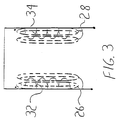
- the differential receiver coils 22 are comprised of two substantially polygonal coils 32 and 34, which are electrically connected to one another in a differential circuit relationship such that the electrical signals induced within the coils by electromagnetic energy are subtracted from one another so as to form a differential output signal.
- a schematic illustration of the differential coils 22 is illustrated in Fig. 3.
- both receiving coils will not receive equally intense transmissions from the transponder. Since the strength of the transponder field drops off at the rate of 1/d 5 , separating the receiver coils will help to assure that the energy of the transponder field is primarily only received by one receiver coil. Naturally, the differential receiver coils will work if disposed in positions that are not diametrically opposed, and therefore not separated by as large of a distance. Thus, as long as the receiver coils are not positioned adjacent to one another, there should be some significant difference in the energy received by each receiver coil from the transponder.
- both coils would also generally receive approximately equal levels of substantially uniform interference energy created by other nearby transmission sources.
- the positioning of the receiver coils 22 within the transmitter coil 20 is an important aspect of the present invention, in that it allows the presence of the substantially equal and opposite transmission fields, together with other substantially uniform magnetic fields, to be cancelled by the differential nature of the two coils.
- differentially electrically connecting the receiver coils so as to subtract the output signals of the individual coils from one another, it is possible to produce a combined output signal which has a near zero voltage amplitude when the two coils receive approximately equal quantities of energy, and a maximum voltage amplitude when one of the coils receives more energy from an electromagnetic field than does the other receiver coil.
- the electrical symmetry of the reader system must be maintained such that more of the energy of the transponder field can be intercepted by one receiver coil than the other receiver coil, or else the differential coils will not be able to accurately detect the presence of the transponder. It is also important to note that in the event that modifications cause the receiver coils to be linked with flux fields of different or variable intensities, the physical or electrical characteristics of the receiver coils can correspondingly be modified, such that even if the receiver coils are not symmetrical with respect to the energy received, the differential output signal can still be zero when both coils are exposed to substantially uniform fields.
- the reader 14 can accurately detect the presence of the transponder 30 at distances of up to at least 8 inches away.
- this increase in detection range over the prior art relates to the reader's ability to cancel out the relative presence of all but the transponder field when that field is primarily detected by only one receiver coil.
- the ability of the reader 14 to detect the transponder assembly 30 at such distances is also enhanced through usage of the coil assembly of the preferred embodiment of the present invention, as will be described below.
- the transponder 30 is positioned so as to receive the magnetic field generated by the transmitting coil 20.
- the strength of the electromagnetic field 38 retransmitted by the transponder is so small that it is effectively incapable of being detected by the transmitter coil.
- the transponder field 38 is, however, within the detectable range of the receiving coil 34. This is true because when the difference between the output of coil 32 is taken from the output of coil 34, the amplitude of the combined output signal will be greater than zero volts by an amount which corresponds to the energy transferred by field 38, thereby indicating the presence of the transponder and allowing for detection of the modulated identification signal contained within the field 38.
- the placement of the two receiver coils within the cylindrical volume of space of the transmission coil creates a high sensitivity to the transponder field and a low sensitivity to the transmitter field.
- the receiver coils 32 and 34 should be formed from a sufficiently large number of turns of wire, i.e., 600 turns, so as to be more sensitive to the transponder field than the transmitter coil.
- the polygonal diameter of the two receiver coils should also each be smaller than the diameter of the transmitter coil, although this is not an absolute requirement if electrical symmetry is maintained.
- the receiver coils 22 are each approximately 20% of the diameter of the transmitter coil. Hence, when the diameter of the transmitter coil is 5-6 inches, the diameter of the receiver coils should be approximately 3/4 to 1 1/4 inches.
- the two receiving coils of the present invention could also be shaped, disposed and oriented in a number of other shapes and positions within the volume space of the transmitter coil and achieve the differential detection effect described in reference to the preferred and alternative embodiments.
- differential receiving coils 22 of the present invention can extend the range over which the transponder assembly's signals can be detected, this range can be further extended, or at least maintained, if the strength of the transponder field 38 is increased. With regard to the present invention, it has been found that maximizing the power coupling between the transmitting coil 20 and the transponder assembly 30 also maximizes the power coupling between the transponder assembly 30 and the receiver coils 32 and 34.
- the strength of the transponder field 38 is increased as a result of the reciprocal relationship which typically exists between a coil and a coupled magnetic field. If a coil produces a current in the presence of a magnetic field, that same magnetic field will be produced by that coil when the same level of current is forced through it. Given that the inductance of a coil is calculated as the ratio of the magnetic flux density surrounding the coil to the current flowing through the coil, and maximizing the power collected by the coil in a given magnetic field maximizes the strength of the magnetic field produced by the coil when driven by that same power, then maximizing the inductance of the coil will likewise maximize the linkage between the coil and the magnetic field.
- FIG. 5 depicts a plan view of the transponder assembly 30 including a coil assembly, shown generally as 150, in accordance with the preferred embodiment of the present invention.
- Fig. 5 also depicts an electronic identification circuit assembly 152, which as previously stated is well know in the prior art and which need not be explained here for a full understanding of the present invention.
- the coil assembly 150 and the circuit assembly 152 are both mounted on a substantially nonconductive support member 154.
- coil assembly 150 is comprised of a primary coil 156 and a secondary coil 158.
- the primary coil 156 is wound around a ferrite rod core 160 with approximately 3,800 turns of 54-gauge conductive wire.
- the core 160 is approximately 0.038 inches in diameter and 0.312 inches in length.
- the coil assembly 150 would be entirely comprised of the core 160 and the primary coil 156, which would have its leads 162 connected to the circuit assembly 152.
- the coil assembly 150 also includes the secondary coil 158, which instead has its leads 164 connected to circuit assembly 152 while the leads 162 of the primary coil are neither connected to the circuit assembly nor to the secondary coil.
- This secondary coil 158 is formed from approximately 500 turns of a separate length of the same type of wire that is used for the primary coil 156. The correlation between the ratio of the number of turns in the primary coil to the number of turns of the secondary coil will be further explained below.
- any inductor such as the primary coil 156
- stray capacitance will generally be present between the turns of the inductor.
- This inter-turn capacitance appears across the inductor and creates a parallel resonant circuit with its own inductance.
- the coil is said to be self-resonate. It is known in the prior art to tune a coil to self-resonate at the frequency of the transmitter field because doing so helps to maximize the energy which can be derived from that field.
- prior art transponder systems have all used an additional capacitor in combination with the primary coil in order to bring the resonance of the coil down to the self-resonate frequency of operation. Although use of this additional capacitor makes the primary coil self-resonate, the physical size of the capacitor makes the transponder too large for implantation purposes.
- self-resonate coils can efficiently transfer power from an external field to an electronic circuit, they are extensively used in electronic communication technologies. As used in prior art transponders, however, the resulting signal produced by the coil can often be too powerful for its intended use because the coil must be lightly loaded in order to remain self-resonate. To maintain a light load on the coil, the amount of current induced in the coil must be kept rather small. This small current in combination with the large impedance and inter-turn capacitance of the coil generally results in a larger than desired voltage (in excess or 40 volts) appearing across the parallel resonant circuit. Although this voltage may be divided down, the current level often remains marginal and is therefore sometimes too small to drive the circuit assembly 152.
- the detached primary coil 156 in combination with the secondary coil 158, which serves to transform the impedance of the primary coil to a more useful level.
- the secondary coil 158 is generally wrapped around the rod 160 after the formation of the primary coil 156, but could also be formed before or coincident with formation of the primary coil, since the manner in which the coils are formed does not significantly effect the electrical interaction between them.
- the ferrite core 160 should generally be coated with a thin layer of insulating material to prevent abrasion and subsequent shorting of the insulated wire of the coils.
- the resonant field which is created in the primary coil 156 results in a substantial voltage across the primary coil leads 162. Since this voltage level is significantly above that required to operate the circuit assembly, typically a CMOS variety integrated circuit requiring only 2 to 5 volts, the voltage must be divided down before being applied to the integrated circuit. Dividing the voltage down in this manner creates a significant disadvantage because it requires additional space consuming electrical components and creates heat which must be dissipated to keep the transponder from overheating and irritating the animal in which it is implanted.
- the ratio between the turns of the primary coil 156 and the secondary coil 158 serves to create a proportional change between the impedance of the primary coil and the secondary coil. For example, if the number of turns of the secondary coil 158 is the same as the number of turns of the primary coil 156 (i.e., a 1:1 ratio), the secondary coil will have the same impedance as the primary coil. Whereas, if the secondary coil 158 has fewer turns than the primary coil 156, so as to create a 2:1 or 7:1 ratio between then, the voltage across the secondary coil will be stepped down, decreased, and the current flowing through the secondary coil will be stepped up, increased, by an amount proportional to the ratio of turns in the coils. Since the impedance of a signal is calculated as the ratio between the voltage to the current in the signal, reducing voltage and increasing the current lowers the impedance of the secondary coil 158.
- this impedance transformation makes the low load impedance of the electronics look like a high impedance to the primary resonant circuit, thereby allowing a light load to be maintained on the primary coil.
- this impedance matching effect could be created by a transformer or by connecting an inductor in parallel with a capacitor, theories which are often used in radio frequency receivers and amplifiers, but which would not be desirable in the present invention because of the physical size of such additional components.
- the 40 volts created across the primary coil can be approximately stepped down by a factor of 7, or to about 6 volts, which is the maximum operating voltage of the CMOS integrated identification electronics. Since the voltage levels will decrease proportionally as the transponder assembly 30 is moved away from interrogator 14 and the identification electronics circuit will operate down to about 1.8 volts, the transponder assembly can be moved a substantial distance from the interrogator 14 and still remain operational.
- the secondary coil 158 resonates at the operating frequency of the identification circuit assembly 152, so as reduce the loss of power when the two devices are interfaced.
- the coil assembly 150 is optimized to receive the electromagnetic field 38 of the interrogator 14 and to convert the energy within that field into sufficient power for operation of the identification circuit assembly 152, the coil assembly 150 is also configured to enhance retransmission of the identification signal from the transponder assembly 30 to the interrogator 14. This enhancement has a significant impact on the utility of the coil assembly 150 because even the smallest increase in that amplitude significantly increases the detectable range of that signal and the range of the transponder's operation.
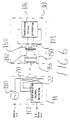
- Fig. 6 schematically illustrates the relationship between the interrogator 14 and the transponder assembly 30.
- Fig. 6 also illustrates an equivalent circuit for the coil assembly 150.
- coil assembly 150 is illustrated as an equivalent circuit to convey information regarding the electrical implementation of the present invention only. Electrical connections appearing between the primary and secondary coils, as well as additional components within that assembly, should be understood to not actually exist in the physical embodiments of the present invention.
- the interrogator 14 is comprised of a signal generator 180 which receives POWER IN from an external source and generates an interrogator signal for transmission to the transponder 30 through the transmitting coil 20.
- the electromagnetic field produced by current flow through the transmitting coil 20 is received by the primary coil 156 of the coil assembly 150.
- the inter-turn capacitance 182 shown here as a separate component for illustration purposes only
- an induction power field is radiated by the primary coil and received by the secondary coil 158.
- the primary coil 156 and the secondary coil 158 are shown to be physically connected, it is once again to be understood that these two coils communicate through an induction power field and not physical wiring.
- the net effect of the secondary coil 158 in combination with the primary coil 156 is that of a transformer, which is why it is shown as such in Fig. 6.
- the secondary coil 158 transforms or converts the impedance level of the energy transmitted by the primary coil 156 to an acceptable impedance level for use in driving the identification signal generator 186.
- the identification signal generator 186 is operative to detect the presence of the interrogator signal output by the secondary coil 158 and to output an identification signal for retransmission to the receiver coils 22.
- the receiver coils detect the presence of the identification signal within the differentiated transmitting field and transmit and output the identification signal to the identification signal detector 188, which analyses the data within the signal regarding the identification of the transponder 30 and outputs an IDENTIFICATION (I.D.) DATA OUT signal for display or storage.
Landscapes
- Engineering & Computer Science (AREA)
- Physics & Mathematics (AREA)
- Health & Medical Sciences (AREA)
- Electromagnetism (AREA)
- Toxicology (AREA)
- General Physics & Mathematics (AREA)
- Theoretical Computer Science (AREA)
- Computer Vision & Pattern Recognition (AREA)
- Artificial Intelligence (AREA)
- Mechanical Engineering (AREA)
- Computer Networks & Wireless Communication (AREA)
- General Health & Medical Sciences (AREA)
- Near-Field Transmission Systems (AREA)
- Arrangements For Transmission Of Measured Signals (AREA)
- Radar Systems Or Details Thereof (AREA)
- Burglar Alarm Systems (AREA)
- Geophysics And Detection Of Objects (AREA)
- Control Of High-Frequency Heating Circuits (AREA)
Applications Claiming Priority (5)
| Application Number | Priority Date | Filing Date | Title |
|---|---|---|---|
| US358310 | 1989-05-26 | ||
| US07/358,310 US5012236A (en) | 1989-05-26 | 1989-05-26 | Electromagnetic energy transmission and detection apparatus |
| US07/400,600 US5084699A (en) | 1989-05-26 | 1989-08-30 | Impedance matching coil assembly for an inductively coupled transponder |
| EP90909258A EP0429617B1 (de) | 1989-05-26 | 1990-05-25 | System zur übertragung und feststellung von elektromagnetischer energie |
| US400600 | 2009-03-09 |
Related Parent Applications (2)
| Application Number | Title | Priority Date | Filing Date |
|---|---|---|---|
| EP90909258A Division EP0429617B1 (de) | 1989-05-26 | 1990-05-25 | System zur übertragung und feststellung von elektromagnetischer energie |
| EP90909258.7 Division | 1990-12-03 |
Publications (3)
| Publication Number | Publication Date |
|---|---|
| EP0812752A2 true EP0812752A2 (de) | 1997-12-17 |
| EP0812752A3 EP0812752A3 (de) | 1998-01-14 |
| EP0812752B1 EP0812752B1 (de) | 2001-09-19 |
Family
ID=27000012
Family Applications (2)
| Application Number | Title | Priority Date | Filing Date |
|---|---|---|---|
| EP90909258A Expired - Lifetime EP0429617B1 (de) | 1989-05-26 | 1990-05-25 | System zur übertragung und feststellung von elektromagnetischer energie |
| EP97109734A Expired - Lifetime EP0812752B1 (de) | 1989-05-26 | 1990-05-25 | System zur Übertragung und Feststellung von elektromagnetischer Energie |
Family Applications Before (1)
| Application Number | Title | Priority Date | Filing Date |
|---|---|---|---|
| EP90909258A Expired - Lifetime EP0429617B1 (de) | 1989-05-26 | 1990-05-25 | System zur übertragung und feststellung von elektromagnetischer energie |
Country Status (8)
| Country | Link |
|---|---|
| US (1) | US5084699A (de) |
| EP (2) | EP0429617B1 (de) |
| AT (2) | ATE205793T1 (de) |
| AU (1) | AU634789B2 (de) |
| DE (2) | DE69032657T2 (de) |
| DK (1) | DK0812752T3 (de) |
| ES (1) | ES2164961T3 (de) |
| WO (1) | WO1990014736A1 (de) |
Cited By (8)
| Publication number | Priority date | Publication date | Assignee | Title |
|---|---|---|---|---|
| WO1999035610A1 (en) * | 1998-01-12 | 1999-07-15 | Sentec Ltd. | Magnetic data tagging |
| WO2000026884A1 (en) * | 1998-10-30 | 2000-05-11 | The Goodyear Tire & Rubber Company | Container with sensor |
| WO2002009022A1 (en) * | 2000-07-21 | 2002-01-31 | Btg International Limited | Multiple tag interrogation system |
| US6538569B1 (en) | 1998-10-30 | 2003-03-25 | The Goodyear Tire & Rubber Company | Container with sensor |
| EP1437680A1 (de) * | 1998-01-12 | 2004-07-14 | Btg International Limited | Magnetische Datenmarkierung |
| EP1521206A2 (de) * | 2003-10-01 | 2005-04-06 | Sony Corporation | Weiterleitungsvorrichtung und Kommunikationssystem |
| EP1870797A3 (de) * | 2006-06-23 | 2008-03-12 | ASTRA Gesellschaft für Asset Management mbH & Co. KG | Informationsträger für Textilien |
| WO2009127246A1 (en) * | 2008-04-16 | 2009-10-22 | Foss Analytical A/S | Wireless information carrier |
Families Citing this family (165)
| Publication number | Priority date | Publication date | Assignee | Title |
|---|---|---|---|---|
| US5250944A (en) * | 1990-10-29 | 1993-10-05 | Bio Medic Data Systems, Inc. | Antenna and driving circuit for transmitting and receiving images to and from a passive transponder |
| NL9100111A (nl) * | 1991-01-23 | 1992-08-17 | Texas Instruments Holland | Antennestelsel voor een ondervraagstation voor het identificeren van objecten. |
| US5266926A (en) * | 1991-05-31 | 1993-11-30 | Avid Marketing, Inc. | Signal transmission and tag power consumption measurement circuit for an inductive reader |
| US5223851A (en) * | 1991-06-05 | 1993-06-29 | Trovan Limited | Apparatus for facilitating interconnection of antenna lead wires to an integrated circuit and encapsulating the assembly to form an improved miniature transponder device |
| EP0549832B1 (de) * | 1991-12-30 | 1997-04-23 | Texas Instruments Incorporated | Eingebauter Chip-Transponder mit Antennenspule |
| US5572226A (en) * | 1992-05-15 | 1996-11-05 | Micron Technology, Inc. | Spherical antenna pattern(s) from antenna(s) arranged in a two-dimensional plane for use in RFID tags and labels |
| US5300120A (en) * | 1992-08-24 | 1994-04-05 | Lipomatrix Incorporated | Implant with electrical transponder marker |
| US5725578A (en) * | 1992-08-24 | 1998-03-10 | Lipomatrix Incoporated | Temporary implant with transponder and methods for locating and indentifying |
| US5855609A (en) * | 1992-08-24 | 1999-01-05 | Lipomatrix, Incorporated (Bvi) | Medical information transponder implant and tracking system |
| US5716407A (en) * | 1992-08-24 | 1998-02-10 | Lipomatrix, Incorporated | Method of rendering identifiable a living tissue implant using an electrical transponder marker |
| US5317330A (en) * | 1992-10-07 | 1994-05-31 | Westinghouse Electric Corp. | Dual resonant antenna circuit for RF tags |
| DE4240628C2 (de) * | 1992-12-03 | 2000-11-09 | Sipra Patent Beteiligung | Überwachungseinrichtung an einer Textilmaschine |
| US5423334A (en) * | 1993-02-01 | 1995-06-13 | C. R. Bard, Inc. | Implantable medical device characterization system |
| US5420757A (en) * | 1993-02-11 | 1995-05-30 | Indala Corporation | Method of producing a radio frequency transponder with a molded environmentally sealed package |
| US5433096A (en) * | 1993-08-26 | 1995-07-18 | Strattec Security Corporation | Key assembly for vehicle ignition locks |
| US6427504B1 (en) * | 1993-08-26 | 2002-08-06 | Strattec Security Corporation | Key assembly for vehicle ignition locks |
| US6035677A (en) | 1993-08-26 | 2000-03-14 | Strattec Security Corporation | Key assembly for vehicle ignition locks |
| AU2692995A (en) * | 1994-05-27 | 1995-12-21 | Avid Marketing, Inc. | Reader having ferromagnetic core field coil |
| DE19520211A1 (de) * | 1994-06-03 | 1996-02-01 | Strattec Security Corp | Elektronische Verriegelungsanordnung für ein Schloßsystem |
| US6472975B1 (en) | 1994-06-20 | 2002-10-29 | Avid Marketing, Inc. | Electronic identification system with improved sensitivity |
| JPH08191259A (ja) * | 1995-01-11 | 1996-07-23 | Sony Chem Corp | 非接触式icカードシステム用送受信装置 |
| US5648765A (en) * | 1995-03-08 | 1997-07-15 | Cresap; Michael S. | Tag tansponder system and method to identify items for purposes such as locating, identifying, counting, inventorying, or the like |
| KR19980703719A (ko) * | 1995-04-12 | 1998-12-05 | 카.마이어 | 교통 통신 시스템용 안테나 시스템 |
| DK0743698T3 (da) * | 1995-05-17 | 2003-12-15 | Siemens Schweiz Ag | Overføringsindretning til trafiktekniske kommunikationsssystemer |
| US5833603A (en) * | 1996-03-13 | 1998-11-10 | Lipomatrix, Inc. | Implantable biosensing transponder |
| US6445296B1 (en) * | 1996-08-21 | 2002-09-03 | A.T.L. Agricultural Technology Limited | Identification apparatus |
| US6362737B1 (en) * | 1998-06-02 | 2002-03-26 | Rf Code, Inc. | Object Identification system with adaptive transceivers and methods of operation |
| US6208235B1 (en) | 1997-03-24 | 2001-03-27 | Checkpoint Systems, Inc. | Apparatus for magnetically decoupling an RFID tag |
| US6264603B1 (en) | 1997-08-07 | 2001-07-24 | St. Croix Medical, Inc. | Middle ear vibration sensor using multiple transducers |
| US6281794B1 (en) * | 1998-01-02 | 2001-08-28 | Intermec Ip Corp. | Radio frequency transponder with improved read distance |
| US6356535B1 (en) * | 1998-02-04 | 2002-03-12 | Micron Technology, Inc. | Communication systems and methods of communicating |
| US6304766B1 (en) | 1998-08-26 | 2001-10-16 | Sensors For Medicine And Science | Optical-based sensing devices, especially for in-situ sensing in humans |
| CN100385232C (zh) * | 1998-08-26 | 2008-04-30 | 医药及科学传感器公司 | 基于光学的感测装置 |
| US6364825B1 (en) | 1998-09-24 | 2002-04-02 | St. Croix Medical, Inc. | Method and apparatus for improving signal quality in implantable hearing systems |
| US6072383A (en) * | 1998-11-04 | 2000-06-06 | Checkpoint Systems, Inc. | RFID tag having parallel resonant circuit for magnetically decoupling tag from its environment |
| US6710708B2 (en) * | 1999-02-05 | 2004-03-23 | Schrader-Bridgeport International, Inc. | Method and apparatus for a remote tire pressure monitoring system |
| US7049935B1 (en) | 1999-07-20 | 2006-05-23 | Stmicroelectronics S.A. | Sizing of an electromagnetic transponder system for a dedicated distant coupling operation |
| FR2796781A1 (fr) * | 1999-07-20 | 2001-01-26 | St Microelectronics Sa | Dimensionnement d'un systeme a transpondeur electromagnetique pour un fonctionnement en hyperproximite |
| US6307468B1 (en) * | 1999-07-20 | 2001-10-23 | Avid Identification Systems, Inc. | Impedance matching network and multidimensional electromagnetic field coil for a transponder interrogator |
| US7710273B2 (en) * | 1999-09-02 | 2010-05-04 | Round Rock Research, Llc | Remote communication devices, radio frequency identification devices, wireless communication systems, wireless communication methods, radio frequency identification device communication methods, and methods of forming a remote communication device |
| FR2804557B1 (fr) * | 2000-01-31 | 2003-06-27 | St Microelectronics Sa | Adaptation de la puissance d'emission d'un lecteur de transpondeur electromagnetique |
| FR2808941B1 (fr) * | 2000-05-12 | 2002-08-16 | St Microelectronics Sa | Validation de la presence d'un transpondeur electromagnetique dans le champ d'un lecteur a demodulation d'amplitude |
| FR2808945B1 (fr) * | 2000-05-12 | 2002-08-16 | St Microelectronics Sa | Evaluation du nombre de transpondeurs electromagnetiques dans le champ d'un lecteur |
| FR2808942B1 (fr) * | 2000-05-12 | 2002-08-16 | St Microelectronics Sa | Validation de la presence d'un transpondeur electromagnetique dans le champ d'un lecteur a demodulation de phase |
| FR2808946A1 (fr) * | 2000-05-12 | 2001-11-16 | St Microelectronics Sa | Validation de la presence d'un transpondeur electromagnetique dans le champ d'un lecteur |
| FR2809235A1 (fr) * | 2000-05-17 | 2001-11-23 | St Microelectronics Sa | Antenne de generation d'un champ electromagnetique pour transpondeur |
| FR2809251B1 (fr) * | 2000-05-17 | 2003-08-15 | St Microelectronics Sa | Dispositif de production d'un champ electromagnetique pour transpondeur |
| US6584301B1 (en) * | 2000-05-25 | 2003-06-24 | Motorola, Inc. | Inductive reader device and method with integrated antenna and signal coupler |
| US6529169B2 (en) * | 2000-07-06 | 2003-03-04 | C. Crane Company, Inc. | Twin coil antenna |
| WO2002007078A1 (fr) * | 2000-07-19 | 2002-01-24 | Hanex Co., Ltd. | Structure de logement et d'installation d'etiquette d'identification et procede de communication d'une telle etiquette |
| FR2812142A1 (fr) * | 2000-07-21 | 2002-01-25 | Microcid Sa | Transpondeur passif et lecteur pour une identification sans contact de tels transpondeurs |
| FR2812986B1 (fr) * | 2000-08-09 | 2002-10-31 | St Microelectronics Sa | Detection d'une signature electrique d'un transpondeur electromagnetique |
| US20030169169A1 (en) * | 2000-08-17 | 2003-09-11 | Luc Wuidart | Antenna generating an electromagnetic field for transponder |
| WO2002048980A1 (en) * | 2000-12-15 | 2002-06-20 | Electrox Corp. | Process for the manufacture of novel, inexpensive radio frequency identification devices |
| TWI252311B (en) * | 2001-05-04 | 2006-04-01 | Sensors For Med & Science Inc | Electro-optical sensing device with reference channel |
| US20030076096A1 (en) * | 2001-10-18 | 2003-04-24 | Microchip Technology Incorporated | Apparatus and method of increasing the sensitivity of magnetic sensors used in magnetic field transmission and detection systems |
| US6894456B2 (en) * | 2001-11-07 | 2005-05-17 | Quallion Llc | Implantable medical power module |
| IL154511A0 (en) * | 2001-11-08 | 2003-09-17 | Vega Elettronica S R L | Ancillary protection system against the unauthorized use of an access and/or ignition key |
| EP1317017A1 (de) * | 2001-12-03 | 2003-06-04 | Siemens Transit Telematic Systems AG | Antennenanordnung zur Erzeugung eines quasi-isotropen Magnetfeldes |
| US7003356B2 (en) * | 2002-03-08 | 2006-02-21 | Quallion Llc | Battery terminal sealing and supporting device and method |
| US7467760B2 (en) * | 2002-04-29 | 2008-12-23 | Allflex Europe Sas | Coil arrangement for radio-frequency identification devices, process and apparatus for making said arrangement |
| US6958551B2 (en) * | 2002-06-25 | 2005-10-25 | Strattec Security Corporation | Vehicle coded ignition lock using a magnetic sensor |
| DE10304479B3 (de) * | 2003-02-04 | 2004-07-22 | Siemens Audiologische Technik Gmbh | Vorrichtung zum Senden und Empfangen von Daten für Fernbedienungen von Hörgeräten |
| EP1667336B1 (de) * | 2003-09-19 | 2013-05-01 | Brother Kogyo Kabushiki Kaisha | Funk-etiketten-leser/-schreiber |
| KR101107555B1 (ko) * | 2004-01-22 | 2012-01-31 | 미코 코포레이션 | 모듈러 무선 주파수 식별 태깅 방법 |
| US20060094923A1 (en) * | 2004-10-01 | 2006-05-04 | Calypso Medical Technologies, Inc. | Systems and methods for treating a patient using radiation therapy |
| WO2006039805A1 (en) * | 2004-10-14 | 2006-04-20 | Quelis Id Systems Inc. | Radio-frequency identification tag |
| US20060103532A1 (en) * | 2004-11-12 | 2006-05-18 | International Paper Company | Electromagnetic pathways to eliminate RFID limitations |
| US7748636B2 (en) * | 2004-11-16 | 2010-07-06 | Dpd Patent Trust Ltd. | Portable identity card reader system for physical and logical access |
| EP1672560B1 (de) * | 2004-12-16 | 2009-04-08 | Schweizerische Bundesbahnen SBB | Induktives Identifikationssystem |
| DE102005000829B4 (de) * | 2005-01-05 | 2008-06-12 | Siemens Ag | Verfahren und Anordnung zur Daten- und/oder Energieübertragung mit Störunterdrückung zwischen Antennen |
| US7775966B2 (en) | 2005-02-24 | 2010-08-17 | Ethicon Endo-Surgery, Inc. | Non-invasive pressure measurement in a fluid adjustable restrictive device |
| US7545272B2 (en) * | 2005-02-08 | 2009-06-09 | Therasense, Inc. | RF tag on test strips, test strip vials and boxes |
| US7927270B2 (en) | 2005-02-24 | 2011-04-19 | Ethicon Endo-Surgery, Inc. | External mechanical pressure sensor for gastric band pressure measurements |
| US8016744B2 (en) | 2005-02-24 | 2011-09-13 | Ethicon Endo-Surgery, Inc. | External pressure-based gastric band adjustment system and method |
| US7775215B2 (en) | 2005-02-24 | 2010-08-17 | Ethicon Endo-Surgery, Inc. | System and method for determining implanted device positioning and obtaining pressure data |
| US7699770B2 (en) | 2005-02-24 | 2010-04-20 | Ethicon Endo-Surgery, Inc. | Device for non-invasive measurement of fluid pressure in an adjustable restriction device |
| US7658196B2 (en) | 2005-02-24 | 2010-02-09 | Ethicon Endo-Surgery, Inc. | System and method for determining implanted device orientation |
| US8066629B2 (en) | 2005-02-24 | 2011-11-29 | Ethicon Endo-Surgery, Inc. | Apparatus for adjustment and sensing of gastric band pressure |
| EP1701287B1 (de) * | 2005-03-07 | 2011-02-09 | Schweizerische Bundesbahnen SBB | Identifikationssystem und Verfahren zur Ermittlung von Bewegungsinformationen |
| US7308292B2 (en) | 2005-04-15 | 2007-12-11 | Sensors For Medicine And Science, Inc. | Optical-based sensing devices |
| US7705733B2 (en) * | 2006-01-06 | 2010-04-27 | Warsaw Orthopedic, Inc. | Coiled RFID tag |
| US20080250341A1 (en) * | 2006-04-06 | 2008-10-09 | Ethicon Endo-Surgery, Inc. | Gui With Trend Analysis for an Implantable Restriction Device and a Data Logger |
| US8152710B2 (en) * | 2006-04-06 | 2012-04-10 | Ethicon Endo-Surgery, Inc. | Physiological parameter analysis for an implantable restriction device and a data logger |
| US8870742B2 (en) | 2006-04-06 | 2014-10-28 | Ethicon Endo-Surgery, Inc. | GUI for an implantable restriction device and a data logger |
| US20080249806A1 (en) * | 2006-04-06 | 2008-10-09 | Ethicon Endo-Surgery, Inc | Data Analysis for an Implantable Restriction Device and a Data Logger |
| US8322624B2 (en) * | 2007-04-10 | 2012-12-04 | Feinics Amatech Teoranta | Smart card with switchable matching antenna |
| US8240022B2 (en) * | 2006-09-26 | 2012-08-14 | Feinics Amatech Teorowita | Methods of connecting an antenna to a transponder chip |
| US8608080B2 (en) * | 2006-09-26 | 2013-12-17 | Feinics Amatech Teoranta | Inlays for security documents |
| US7825867B2 (en) * | 2007-04-26 | 2010-11-02 | Round Rock Research, Llc | Methods and systems of changing antenna polarization |
| US7825869B2 (en) * | 2007-07-03 | 2010-11-02 | Masin Joseph V | Miniature transponders |
| US20090015407A1 (en) * | 2007-07-13 | 2009-01-15 | Micron Technology, Inc. | Rifid tags and methods of designing rfid tags |
| US7777630B2 (en) * | 2007-07-26 | 2010-08-17 | Round Rock Research, Llc | Methods and systems of RFID tags using RFID circuits and antennas having unmatched frequency ranges |
| JP2010537496A (ja) * | 2007-08-13 | 2010-12-02 | クゥアルコム・インコーポレイテッド | 長距離低周波数共振器および素材 |
| US7936268B2 (en) * | 2007-08-31 | 2011-05-03 | Round Rock Research, Llc | Selectively coupling to feed points of an antenna system |
| JP4561796B2 (ja) * | 2007-08-31 | 2010-10-13 | ソニー株式会社 | 受電装置、および電力伝送システム |
| US8187163B2 (en) * | 2007-12-10 | 2012-05-29 | Ethicon Endo-Surgery, Inc. | Methods for implanting a gastric restriction device |
| US8100870B2 (en) | 2007-12-14 | 2012-01-24 | Ethicon Endo-Surgery, Inc. | Adjustable height gastric restriction devices and methods |
| US20090171379A1 (en) * | 2007-12-27 | 2009-07-02 | Ethicon Endo-Surgery, Inc. | Fluid logic for regulating restriction devices |
| US8142452B2 (en) * | 2007-12-27 | 2012-03-27 | Ethicon Endo-Surgery, Inc. | Controlling pressure in adjustable restriction devices |
| US8377079B2 (en) | 2007-12-27 | 2013-02-19 | Ethicon Endo-Surgery, Inc. | Constant force mechanisms for regulating restriction devices |
| US8192350B2 (en) | 2008-01-28 | 2012-06-05 | Ethicon Endo-Surgery, Inc. | Methods and devices for measuring impedance in a gastric restriction system |
| US8337389B2 (en) | 2008-01-28 | 2012-12-25 | Ethicon Endo-Surgery, Inc. | Methods and devices for diagnosing performance of a gastric restriction system |
| US8591395B2 (en) | 2008-01-28 | 2013-11-26 | Ethicon Endo-Surgery, Inc. | Gastric restriction device data handling devices and methods |
| US20090192534A1 (en) * | 2008-01-29 | 2009-07-30 | Ethicon Endo-Surgery, Inc. | Sensor trigger |
| US20090204179A1 (en) * | 2008-02-07 | 2009-08-13 | Ethicon Endo-Surgery, Inc. | Powering implantable restriction systems using temperature |
| US8221439B2 (en) * | 2008-02-07 | 2012-07-17 | Ethicon Endo-Surgery, Inc. | Powering implantable restriction systems using kinetic motion |
| US7844342B2 (en) | 2008-02-07 | 2010-11-30 | Ethicon Endo-Surgery, Inc. | Powering implantable restriction systems using light |
| US8114345B2 (en) * | 2008-02-08 | 2012-02-14 | Ethicon Endo-Surgery, Inc. | System and method of sterilizing an implantable medical device |
| US8057492B2 (en) * | 2008-02-12 | 2011-11-15 | Ethicon Endo-Surgery, Inc. | Automatically adjusting band system with MEMS pump |
| US8591532B2 (en) | 2008-02-12 | 2013-11-26 | Ethicon Endo-Sugery, Inc. | Automatically adjusting band system |
| US8034065B2 (en) * | 2008-02-26 | 2011-10-11 | Ethicon Endo-Surgery, Inc. | Controlling pressure in adjustable restriction devices |
| US8233995B2 (en) | 2008-03-06 | 2012-07-31 | Ethicon Endo-Surgery, Inc. | System and method of aligning an implantable antenna |
| US20090228063A1 (en) * | 2008-03-06 | 2009-09-10 | Ethicon Endo-Surgery, Inc. | System and method of communicating with an implantable antenna |
| US8187162B2 (en) * | 2008-03-06 | 2012-05-29 | Ethicon Endo-Surgery, Inc. | Reorientation port |
| US8179232B2 (en) * | 2008-05-05 | 2012-05-15 | Round Rock Research, Llc | RFID interrogator with adjustable signal characteristics |
| US7852221B2 (en) * | 2008-05-08 | 2010-12-14 | Round Rock Research, Llc | RFID devices using RFID circuits and antennas having unmatched frequency ranges |
| US8712334B2 (en) | 2008-05-20 | 2014-04-29 | Micron Technology, Inc. | RFID device using single antenna for multiple resonant frequency ranges |
| US8115637B2 (en) | 2008-06-03 | 2012-02-14 | Micron Technology, Inc. | Systems and methods to selectively connect antennas to receive and backscatter radio frequency signals |
| US8474726B2 (en) | 2010-08-12 | 2013-07-02 | Feinics Amatech Teoranta | RFID antenna modules and increasing coupling |
| US8366009B2 (en) | 2010-08-12 | 2013-02-05 | Féinics Amatech Teoranta | Coupling in and to RFID smart cards |
| US9033250B2 (en) | 2010-08-12 | 2015-05-19 | Féinics Amatech Teoranta | Dual interface smart cards, and methods of manufacturing |
| US8789762B2 (en) | 2010-08-12 | 2014-07-29 | Feinics Amatech Teoranta | RFID antenna modules and methods of making |
| WO2012020073A2 (en) | 2010-08-12 | 2012-02-16 | Féinics Amatech Teoranta Limited | Rfid antenna modules and increasing coupling |
| US8870080B2 (en) | 2010-08-12 | 2014-10-28 | Féinics Amatech Teoranta | RFID antenna modules and methods |
| US9112272B2 (en) | 2010-08-12 | 2015-08-18 | Feinics Amatech Teoranta | Antenna modules for dual interface smart cards, booster antenna configurations, and methods |
| US9195932B2 (en) | 2010-08-12 | 2015-11-24 | Féinics Amatech Teoranta | Booster antenna configurations and methods |
| US8991712B2 (en) | 2010-08-12 | 2015-03-31 | Féinics Amatech Teoranta | Coupling in and to RFID smart cards |
| CN103733460B (zh) * | 2011-07-08 | 2019-07-23 | 奥克兰联合服务有限公司 | 用于感应功率传输系统的磁结构的互操作性 |
| CN103930906A (zh) | 2011-08-08 | 2014-07-16 | 菲尼克斯阿美特克有限公司 | 改进rfid智能卡中的耦合和改进与rfid智能卡的耦合 |
| US10518518B2 (en) | 2013-01-18 | 2019-12-31 | Féinics Amatech Teoranta | Smart cards with metal layer(s) and methods of manufacture |
| US10733494B2 (en) | 2014-08-10 | 2020-08-04 | Féinics Amatech Teoranta | Contactless metal card constructions |
| US9622359B2 (en) | 2011-08-08 | 2017-04-11 | Féinics Amatech Teoranta | RFID transponder chip modules |
| US9634391B2 (en) | 2011-08-08 | 2017-04-25 | Féinics Amatech Teoranta | RFID transponder chip modules |
| US9812782B2 (en) | 2011-08-08 | 2017-11-07 | Féinics Amatech Teoranta | Coupling frames for RFID devices |
| US10867235B2 (en) | 2011-08-08 | 2020-12-15 | Féinics Amatech Teoranta | Metallized smartcard constructions and methods |
| US9697459B2 (en) | 2014-08-10 | 2017-07-04 | Féinics Amatech Teoranta | Passive smart cards, metal cards, payment objects and smart jewelry |
| US9475086B2 (en) | 2013-01-18 | 2016-10-25 | Féinics Amatech Teoranta | Smartcard with coupling frame and method of increasing activation distance of a transponder chip module |
| US9798968B2 (en) | 2013-01-18 | 2017-10-24 | Féinics Amatech Teoranta | Smartcard with coupling frame and method of increasing activation distance of a transponder chip module |
| JP2014529927A (ja) | 2011-08-08 | 2014-11-13 | フェニックスアマテック テオランタ | Rfidスマートカードに関する結合の向上 |
| US9489613B2 (en) | 2011-08-08 | 2016-11-08 | Féinics Amatech Teoranta | RFID transponder chip modules with a band of the antenna extending inward |
| US9836684B2 (en) | 2014-08-10 | 2017-12-05 | Féinics Amatech Teoranta | Smart cards, payment objects and methods |
| WO2013034426A1 (en) | 2011-09-11 | 2013-03-14 | Féinics Amatech Teoranta | Rfid antenna modules and methods of making |
| US10182472B2 (en) | 2011-12-29 | 2019-01-15 | Arcelik Anonim Sirketi | Wireless kitchen appliance operated on induction heating cooker |
| US10129935B2 (en) * | 2011-12-29 | 2018-11-13 | Arcelik Anonim Sirketi | Wireless kitchen appliance operated on an induction heating cooker |
| CA2860936A1 (en) | 2012-02-05 | 2013-08-08 | Feinics Amatech Teoranta | Rfid antenna modules and methods |
| US10824931B2 (en) | 2012-08-30 | 2020-11-03 | Féinics Amatech Teoranta | Contactless smartcards with multiple coupling frames |
| US10552722B2 (en) | 2014-08-10 | 2020-02-04 | Féinics Amatech Teoranta | Smartcard with coupling frame antenna |
| DE102012017390A1 (de) * | 2012-09-01 | 2014-05-15 | Volkswagen Aktiengesellschaft | Spulenanordnung zum Erzeugen eines rotierenden elektromagnetischen Felds und Ortungssystem zum Bestimmen einer Position eines Identifikationsgebers |
| US11354560B2 (en) | 2013-01-18 | 2022-06-07 | Amatech Group Limited | Smartcards with multiple coupling frames |
| US11551051B2 (en) | 2013-01-18 | 2023-01-10 | Amatech Group Limiied | Coupling frames for smartcards with various module opening shapes |
| US10599972B2 (en) | 2013-01-18 | 2020-03-24 | Féinics Amatech Teoranta | Smartcard constructions and methods |
| US10977542B2 (en) | 2013-01-18 | 2021-04-13 | Amtech Group Limited Industrial Estate | Smart cards with metal layer(s) and methods of manufacture |
| US11354558B2 (en) | 2013-01-18 | 2022-06-07 | Amatech Group Limited | Contactless smartcards with coupling frames |
| US10248902B1 (en) | 2017-11-06 | 2019-04-02 | Féinics Amatech Teoranta | Coupling frames for RFID devices |
| US20150365738A1 (en) * | 2014-01-09 | 2015-12-17 | Rick Purvis | Telemetry arrangements for implantable devices |
| DE102014109998A1 (de) * | 2014-07-16 | 2016-01-21 | Paul Vahle Gmbh & Co. Kg | Parallelschwingkreis Pickup mit Auskoppelwicklung |
| WO2018102630A1 (en) | 2016-12-01 | 2018-06-07 | Avery Dennison Retail Information Services, Llc | Systems and methods for improving performance of rfid tags |
| EP3762871A4 (de) | 2018-03-07 | 2021-11-10 | X-Card Holdings, LLC | Metallkarte |
| GB2575685B (en) * | 2018-07-20 | 2020-11-18 | Drayson Tech Europe Ltd | Circuitry for use in smart cards and other applications |
| US11205106B2 (en) * | 2019-09-19 | 2021-12-21 | Sensormatic Electronics, LLC | Self-detaching anti-theft device with energy limit |
| DE102020004293A1 (de) | 2020-07-17 | 2022-01-20 | Mühlbauer Gmbh & Co. Kg | Sicherheitsdokument, Verfahren zur Verifikation eines Sicherheitsdokuments und Lesegerät für ein Sicherheitsdokument |
| USD943024S1 (en) | 2020-07-30 | 2022-02-08 | Federal Card Services, LLC | Asymmetrical arrangement of contact pads and connection bridges of a transponder chip module |
| USD942538S1 (en) | 2020-07-30 | 2022-02-01 | Federal Card Services, LLC | Asymmetrical arrangement of contact pads and connection bridges of a transponder chip module |
| RU206804U1 (ru) * | 2021-05-21 | 2021-09-28 | Общество с ограниченной ответственностью "Всесоюзный научно-исследовательский центр транспортных технологий" (ООО "ВНИЦТТ") | Устройство для получения электрической энергии при движении железнодорожного транспортного средства |
Citations (5)
| Publication number | Priority date | Publication date | Assignee | Title |
|---|---|---|---|---|
| EP0084400A2 (de) * | 1982-01-14 | 1983-07-27 | N.V. Nederlandsche Apparatenfabriek NEDAP | Detektionssystem |
| US4450431A (en) * | 1981-05-26 | 1984-05-22 | Hochstein Peter A | Condition monitoring system (tire pressure) |
| US4630044A (en) * | 1982-12-23 | 1986-12-16 | Ant Nachrichtentechnik Gmbh | Programmable inductively coupled transponder |
| US4658263A (en) * | 1985-02-11 | 1987-04-14 | Allied Corporation | Dual antenna for magnetic markers |
| US4782342A (en) * | 1986-08-04 | 1988-11-01 | Walton Charles A | Proximity identification system with lateral flux paths |
Family Cites Families (3)
| Publication number | Priority date | Publication date | Assignee | Title |
|---|---|---|---|---|
| US3859624A (en) * | 1972-09-05 | 1975-01-07 | Thomas A Kriofsky | Inductively coupled transmitter-responder arrangement |
| US4361153A (en) * | 1980-05-27 | 1982-11-30 | Cordis Corporation | Implant telemetry system |
| US4868915A (en) * | 1984-02-23 | 1989-09-19 | Allied Corporation | Keyless entry system having remote marker for motor vehicles |
-
1989
- 1989-08-30 US US07/400,600 patent/US5084699A/en not_active Expired - Lifetime
-
1990
- 1990-05-25 DE DE69032657T patent/DE69032657T2/de not_active Expired - Lifetime
- 1990-05-25 EP EP90909258A patent/EP0429617B1/de not_active Expired - Lifetime
- 1990-05-25 EP EP97109734A patent/EP0812752B1/de not_active Expired - Lifetime
- 1990-05-25 DE DE69033808T patent/DE69033808T2/de not_active Expired - Lifetime
- 1990-05-25 AT AT97109734T patent/ATE205793T1/de not_active IP Right Cessation
- 1990-05-25 DK DK97109734T patent/DK0812752T3/da active
- 1990-05-25 ES ES97109734T patent/ES2164961T3/es not_active Expired - Lifetime
- 1990-05-25 WO PCT/US1990/002972 patent/WO1990014736A1/en active IP Right Grant
- 1990-05-25 AU AU58171/90A patent/AU634789B2/en not_active Ceased
- 1990-05-25 AT AT90909258T patent/ATE171335T1/de not_active IP Right Cessation
Patent Citations (5)
| Publication number | Priority date | Publication date | Assignee | Title |
|---|---|---|---|---|
| US4450431A (en) * | 1981-05-26 | 1984-05-22 | Hochstein Peter A | Condition monitoring system (tire pressure) |
| EP0084400A2 (de) * | 1982-01-14 | 1983-07-27 | N.V. Nederlandsche Apparatenfabriek NEDAP | Detektionssystem |
| US4630044A (en) * | 1982-12-23 | 1986-12-16 | Ant Nachrichtentechnik Gmbh | Programmable inductively coupled transponder |
| US4658263A (en) * | 1985-02-11 | 1987-04-14 | Allied Corporation | Dual antenna for magnetic markers |
| US4782342A (en) * | 1986-08-04 | 1988-11-01 | Walton Charles A | Proximity identification system with lateral flux paths |
Cited By (10)
| Publication number | Priority date | Publication date | Assignee | Title |
|---|---|---|---|---|
| WO1999035610A1 (en) * | 1998-01-12 | 1999-07-15 | Sentec Ltd. | Magnetic data tagging |
| EP1437680A1 (de) * | 1998-01-12 | 2004-07-14 | Btg International Limited | Magnetische Datenmarkierung |
| WO2000026884A1 (en) * | 1998-10-30 | 2000-05-11 | The Goodyear Tire & Rubber Company | Container with sensor |
| JP2002529833A (ja) * | 1998-10-30 | 2002-09-10 | ザ・グッドイヤー・タイヤ・アンド・ラバー・カンパニー | センサ付き容器 |
| US6538569B1 (en) | 1998-10-30 | 2003-03-25 | The Goodyear Tire & Rubber Company | Container with sensor |
| WO2002009022A1 (en) * | 2000-07-21 | 2002-01-31 | Btg International Limited | Multiple tag interrogation system |
| EP1521206A2 (de) * | 2003-10-01 | 2005-04-06 | Sony Corporation | Weiterleitungsvorrichtung und Kommunikationssystem |
| EP1521206A3 (de) * | 2003-10-01 | 2006-12-13 | Sony Corporation | Weiterleitungsvorrichtung und Kommunikationssystem |
| EP1870797A3 (de) * | 2006-06-23 | 2008-03-12 | ASTRA Gesellschaft für Asset Management mbH & Co. KG | Informationsträger für Textilien |
| WO2009127246A1 (en) * | 2008-04-16 | 2009-10-22 | Foss Analytical A/S | Wireless information carrier |
Also Published As
| Publication number | Publication date |
|---|---|
| EP0429617A1 (de) | 1991-06-05 |
| DK0812752T3 (da) | 2001-11-19 |
| AU634789B2 (en) | 1993-03-04 |
| DE69033808D1 (de) | 2001-10-25 |
| ATE171335T1 (de) | 1998-10-15 |
| DE69032657D1 (de) | 1998-10-22 |
| EP0429617B1 (de) | 1998-09-16 |
| ATE205793T1 (de) | 2001-10-15 |
| EP0429617A4 (en) | 1993-05-12 |
| AU5817190A (en) | 1990-12-18 |
| US5084699A (en) | 1992-01-28 |
| WO1990014736A1 (en) | 1990-11-29 |
| DE69032657T2 (de) | 1999-05-27 |
| EP0812752A3 (de) | 1998-01-14 |
| EP0812752B1 (de) | 2001-09-19 |
| DE69033808T2 (de) | 2002-04-25 |
| ES2164961T3 (es) | 2002-03-01 |
Similar Documents
| Publication | Publication Date | Title |
|---|---|---|
| EP0812752B1 (de) | System zur Übertragung und Feststellung von elektromagnetischer Energie | |
| US5012236A (en) | Electromagnetic energy transmission and detection apparatus | |
| US5095309A (en) | Method and apparatus for modulating and detecting a subcarrier signal for an inductively coupled transponder | |
| US4782342A (en) | Proximity identification system with lateral flux paths | |
| US5625370A (en) | Identification system antenna with impedance transformer | |
| EP0434817B1 (de) | Näherungsdetektionsgerät | |
| EP0253877B1 (de) | Antennensysteme | |
| AU2010315240B2 (en) | Signal cancelling transmit/receive multi-loop antenna for a radio frequency identification reader | |
| US5021778A (en) | Capacitance coupled proximity identification system | |
| US5198807A (en) | Method and apparatus for producing a subcarrier signal for transmission by an inductively coupled transponder | |
| JPH08296354A (ja) | 送受信機用改善インダクタ/アンテナ | |
| US7764181B2 (en) | Inductively coupled loop antenna for a radio frequency identification reader | |
| EP0578701A4 (de) | Warensortiersystem. | |
| US3911389A (en) | Magnetic gradient vehicle detector | |
| US6848621B2 (en) | Transponder unit and transport unit and card | |
| EP0285188B1 (de) | Verfahren zur Anbringung eines elektronischen Antwortgebers in einem oder in der Nähe eines elektrisch leitenden Gegenstandes und elektrisch leitender Gegenstand, versehen mit einem solchen Antwortgeber | |
| WO2009005504A1 (en) | Inductively coupled loop antenna for a radio frequency identification reader | |
| US4888474A (en) | Proximity identification system with lateral flux magnetic rod coupling | |
| WO2003034349A2 (en) | Reducing orientation directivity and improving operating distance of magnetic sensor coils in a magnetic field | |
| US3839700A (en) | Traffic sensor | |
| EP0557297B1 (de) | Verfahren und gerät zur modulation und detektion eines hilfsträgersignals für einen transponder mit induktiver kopplung | |
| US6690278B2 (en) | Electronic marker for metallic valve box covers | |
| AU2007355877B2 (en) | Inductively coupled loop antenna for a radio frequency identification reader |
Legal Events
| Date | Code | Title | Description |
|---|---|---|---|
| PUAI | Public reference made under article 153(3) epc to a published international application that has entered the european phase |
Free format text: ORIGINAL CODE: 0009012 |
|
| PUAL | Search report despatched |
Free format text: ORIGINAL CODE: 0009013 |
|
| AC | Divisional application: reference to earlier application |
Ref document number: 429617 Country of ref document: EP |
|
| AK | Designated contracting states |
Kind code of ref document: A2 Designated state(s): AT BE CH DE DK ES FR GB IT LI LU NL SE |
|
| AK | Designated contracting states |
Kind code of ref document: A3 Designated state(s): AT BE CH DE DK ES FR GB IT LI LU NL SE |
|
| RAP1 | Party data changed (applicant data changed or rights of an application transferred) |
Owner name: TROVAN LIMITED |
|
| RAP1 | Party data changed (applicant data changed or rights of an application transferred) |
Owner name: ALGERNON PROMOTIONS INC. |
|
| 17P | Request for examination filed |
Effective date: 19980617 |
|
| GRAG | Despatch of communication of intention to grant |
Free format text: ORIGINAL CODE: EPIDOS AGRA |
|
| 17Q | First examination report despatched |
Effective date: 20000530 |
|
| GRAG | Despatch of communication of intention to grant |
Free format text: ORIGINAL CODE: EPIDOS AGRA |
|
| GRAH | Despatch of communication of intention to grant a patent |
Free format text: ORIGINAL CODE: EPIDOS IGRA |
|
| GRAH | Despatch of communication of intention to grant a patent |
Free format text: ORIGINAL CODE: EPIDOS IGRA |
|
| GRAA | (expected) grant |
Free format text: ORIGINAL CODE: 0009210 |
|
| AC | Divisional application: reference to earlier application |
Ref document number: 429617 Country of ref document: EP |
|
| AK | Designated contracting states |
Kind code of ref document: B1 Designated state(s): AT BE CH DE DK ES FR GB IT LI LU NL SE |
|
| REF | Corresponds to: |
Ref document number: 205793 Country of ref document: AT Date of ref document: 20011015 Kind code of ref document: T |
|
| REG | Reference to a national code |
Ref country code: CH Ref legal event code: NV Representative=s name: TROESCH SCHEIDEGGER WERNER AG Ref country code: CH Ref legal event code: EP |
|
| REF | Corresponds to: |
Ref document number: 69033808 Country of ref document: DE Date of ref document: 20011025 |
|
| REG | Reference to a national code |
Ref country code: DK Ref legal event code: T3 |
|
| REG | Reference to a national code |
Ref country code: GB Ref legal event code: IF02 |
|
| ET | Fr: translation filed | ||
| REG | Reference to a national code |
Ref country code: ES Ref legal event code: FG2A Ref document number: 2164961 Country of ref document: ES Kind code of ref document: T3 |
|
| PG25 | Lapsed in a contracting state [announced via postgrant information from national office to epo] |
Ref country code: LU Free format text: LAPSE BECAUSE OF NON-PAYMENT OF DUE FEES Effective date: 20020525 |
|
| PLBE | No opposition filed within time limit |
Free format text: ORIGINAL CODE: 0009261 |
|
| STAA | Information on the status of an ep patent application or granted ep patent |
Free format text: STATUS: NO OPPOSITION FILED WITHIN TIME LIMIT |
|
| 26N | No opposition filed | ||
| PGFP | Annual fee paid to national office [announced via postgrant information from national office to epo] |
Ref country code: NL Payment date: 20090527 Year of fee payment: 20 Ref country code: ES Payment date: 20090521 Year of fee payment: 20 Ref country code: DK Payment date: 20090513 Year of fee payment: 20 |
|
| PGFP | Annual fee paid to national office [announced via postgrant information from national office to epo] |
Ref country code: SE Payment date: 20090514 Year of fee payment: 20 Ref country code: IT Payment date: 20090528 Year of fee payment: 20 Ref country code: FR Payment date: 20090513 Year of fee payment: 20 Ref country code: AT Payment date: 20090515 Year of fee payment: 20 |
|
| PGFP | Annual fee paid to national office [announced via postgrant information from national office to epo] |
Ref country code: BE Payment date: 20090622 Year of fee payment: 20 |
|
| PGFP | Annual fee paid to national office [announced via postgrant information from national office to epo] |
Ref country code: CH Payment date: 20090518 Year of fee payment: 20 |
|
| PGFP | Annual fee paid to national office [announced via postgrant information from national office to epo] |
Ref country code: GB Payment date: 20090522 Year of fee payment: 20 Ref country code: DE Payment date: 20090704 Year of fee payment: 20 |
|
| REG | Reference to a national code |
Ref country code: NL Ref legal event code: V4 Effective date: 20100525 |
|
| BE20 | Be: patent expired |
Owner name: *ALGERNON PROMOTIONS INC. Effective date: 20100525 |
|
| REG | Reference to a national code |
Ref country code: CH Ref legal event code: PL |
|
| REG | Reference to a national code |
Ref country code: DK Ref legal event code: EUP |
|
| EUG | Se: european patent has lapsed | ||
| REG | Reference to a national code |
Ref country code: ES Ref legal event code: FD2A Effective date: 20100526 |
|
| PG25 | Lapsed in a contracting state [announced via postgrant information from national office to epo] |
Ref country code: NL Free format text: LAPSE BECAUSE OF EXPIRATION OF PROTECTION Effective date: 20100525 |
|
| PG25 | Lapsed in a contracting state [announced via postgrant information from national office to epo] |
Ref country code: ES Free format text: LAPSE BECAUSE OF EXPIRATION OF PROTECTION Effective date: 20100526 |
|
| PG25 | Lapsed in a contracting state [announced via postgrant information from national office to epo] |
Ref country code: GB Free format text: LAPSE BECAUSE OF EXPIRATION OF PROTECTION Effective date: 20100524 |
|
| PG25 | Lapsed in a contracting state [announced via postgrant information from national office to epo] |
Ref country code: DE Free format text: LAPSE BECAUSE OF EXPIRATION OF PROTECTION Effective date: 20100525 |