EP0812480B1 - Dichtendes rohr element für die pole eines elektrischen akkus - Google Patents
Dichtendes rohr element für die pole eines elektrischen akkus Download PDFInfo
- Publication number
- EP0812480B1 EP0812480B1 EP96944656A EP96944656A EP0812480B1 EP 0812480 B1 EP0812480 B1 EP 0812480B1 EP 96944656 A EP96944656 A EP 96944656A EP 96944656 A EP96944656 A EP 96944656A EP 0812480 B1 EP0812480 B1 EP 0812480B1
- Authority
- EP
- European Patent Office
- Prior art keywords
- pole
- sealing element
- tubular body
- sealing
- lid
- Prior art date
- Legal status (The legal status is an assumption and is not a legal conclusion. Google has not performed a legal analysis and makes no representation as to the accuracy of the status listed.)
- Expired - Lifetime
Links
- 238000007789 sealing Methods 0.000 title claims abstract description 44
- 229920001971 elastomer Polymers 0.000 claims description 5
- 239000013013 elastic material Substances 0.000 claims description 4
- 229920002943 EPDM rubber Polymers 0.000 claims description 3
- 230000001458 anti-acid effect Effects 0.000 claims description 3
- 238000000034 method Methods 0.000 description 4
- 238000010168 coupling process Methods 0.000 description 3
- 239000003792 electrolyte Substances 0.000 description 3
- 230000006835 compression Effects 0.000 description 1
- 238000007906 compression Methods 0.000 description 1
- 239000004020 conductor Substances 0.000 description 1
- 230000008878 coupling Effects 0.000 description 1
- 238000005859 coupling reaction Methods 0.000 description 1
- 239000013536 elastomeric material Substances 0.000 description 1
- 230000008030 elimination Effects 0.000 description 1
- 238000003379 elimination reaction Methods 0.000 description 1
- 238000004519 manufacturing process Methods 0.000 description 1
- 239000000463 material Substances 0.000 description 1
- 230000007246 mechanism Effects 0.000 description 1
Images

Classifications
-
- H—ELECTRICITY
- H01—ELECTRIC ELEMENTS
- H01M—PROCESSES OR MEANS, e.g. BATTERIES, FOR THE DIRECT CONVERSION OF CHEMICAL ENERGY INTO ELECTRICAL ENERGY
- H01M50/00—Constructional details or processes of manufacture of the non-active parts of electrochemical cells other than fuel cells, e.g. hybrid cells
- H01M50/10—Primary casings; Jackets or wrappings
- H01M50/172—Arrangements of electric connectors penetrating the casing
-
- Y—GENERAL TAGGING OF NEW TECHNOLOGICAL DEVELOPMENTS; GENERAL TAGGING OF CROSS-SECTIONAL TECHNOLOGIES SPANNING OVER SEVERAL SECTIONS OF THE IPC; TECHNICAL SUBJECTS COVERED BY FORMER USPC CROSS-REFERENCE ART COLLECTIONS [XRACs] AND DIGESTS
- Y02—TECHNOLOGIES OR APPLICATIONS FOR MITIGATION OR ADAPTATION AGAINST CLIMATE CHANGE
- Y02E—REDUCTION OF GREENHOUSE GAS [GHG] EMISSIONS, RELATED TO ENERGY GENERATION, TRANSMISSION OR DISTRIBUTION
- Y02E60/00—Enabling technologies; Technologies with a potential or indirect contribution to GHG emissions mitigation
- Y02E60/10—Energy storage using batteries
Definitions
- the present invention concerns a sealing tubular element, particularly suited to be applied to the poles of electric accumulators.
- poles consist of bodies having an essentially cylindrical shape which are provided with connecting means, suited to connect each pole to its respective cable supplying the corresponding engine, and with sealing mechanisms, co-operating with each pole and with the lid of the container wherein the elements are contained, suited to prevent the leaking out of electrolyte.
- the upper part of the pole is arranged passing through the corresponding hole drilled in the lid to which it is secured by means of a sealing ring-nut which can be threaded on the pole or on the lid, if the pole or the lid are threaded, or it can be cylindrical and inserted by pressure, if the pole or the lid are not threaded.
- a sealing ring-nut which can be threaded on the pole or on the lid, if the pole or the lid are threaded, or it can be cylindrical and inserted by pressure, if the pole or the lid are not threaded.
- Ring-nuts inserted by pressure are usually preferred to threaded ring-nuts, since they make it unnecessary to have to realize threaded poles and seats of lids which are more costly and also because said ring-nuts can sometimes act as sealing gaskets for the electrolyte, if they are made of rubber.
- EP 0319741-A discloses a tubular sealing element for poles of a battery made of elastomeric material where the sealing is substantially assured by two annular opposite protrusions, the first one cooperating with a plane surface present in recess of the pole, the second one cooperating both with a similar plane surface recess of the pole and with the annular surface becoming to the bottom of seat of the lid in which the tubular sealing element is secured.
- the present invention proposes to overcome such an inconvenience and has the purpose of realizing a sealing element for the poles of electric accumulators which can be mounted without mechanically stressing the elements.
- Another purpose is to perform the coupling much more easily.
- Another purpose is to permit the elimination of all the sealing gaskets which in the embodiments belonging to the known technique are interposed between the ring-nut and the pole.
- the tubular element according to the present invention is made of rubber and presents externally annular projections which ensure the sealing against the wall of the seat of the lid within which it is lodged.
- the use of the sealing tubular element according to the invention makes it possible not to mechanically stress the accumulator elements during the assembly process. Moreover, the assembling operations are simpler, faster and, therefore, less costly.
- the manufacture of the sealing tubular element according to the invention is also less costly.
- sealing element is made of elastic material, preferably of anti-acid rubber or EPDM or similar, and is itself the sealing element, it makes it possible to do away with the gaskets, which would be necessary if ring-nuts belonging to the known technique were used.
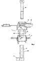
- the sealing element according to the invention which is indicated as a whole with 1, consists of a tubular body 10 which, as can also be observed in Fig. 2 and in Fig. 3, is coupled extemally with pole 2 of the accumulator and internally with an annular seat 3 obtained peripherically to hole 4 for the passage of said pole 2, drilled in lid 5 of the container, not represented in the drawing, within which the elements 6 of the accumulator are arranged.
- tubular body 10 of said tubular element 1 presents a through-hole 7 through which it couples itself with pole 2 there, where the inner surface 27 of said hole presents a profile having the shape of an essentially truncated cone having an angle of inclination 29 diverging toward the elements 6 of the accumulator with which pole 2 is connected.
- At least one part -of the outer surface 20 of the same tubular body 10 presents the essential shape of a truncated cone having an angle of inclination 21 also diverging toward the same elements 6 of the accumulator.
- a collar 25 having the profile of an essentially truncated cone which presents an inclination 26 diverging toward the elements 6 of the accumulator and having a greater value as compared with the inclination 29 of the inner surface 27 of the same hole 7.
- tubular element 1 presents externally a plurality of projections 9 suited to co-operate in order to create a seal against wall 31 of the annular seat 3.
- the tubular element 1 can also be without said annular projections 9 and its external surface can be completely smooth, slanted at an angle 21 or it can also be cylindrical.
- the inner surface 27 of hole 7, instead of being slanted at an angle 29, can also be cylindrical.
- an upper sealing area 225 which is located in correspondence with the collar 25, and a lower sealing area 227, arranged in correspondence with the annular area 28, placed on the opposite side of collar 25, are created.
- the outer surface of the tubular element 1 creates together with seat 3 of lid 5, which lodges the tubular element 1, a sealing area 327 on the opposite side of the lower sealing area 227.
- connection is perfected by means of cover 14 protecting the electric cable 15 and of the securing screw 16.
- FIG. 4 A different embodiment of the sealing element according to the invention is represented in Fig. 4, wherein it can be observed that said sealing element, indicated as a whole with 100, presents the sealing collar 125 against the pole and it consists of a projecting ring facing the interior of hole 70 of said sealing element 100.
- the sealing element according to the invention may present a smooth outer surface or eventually even a cylindrical shape. Even part of the lateral surface of its inner hole, which extends beyond the collar which creates the interference against the pole, may present a cylindrical shape.
- the sealing tubular element 1 is preferably made of anti-acid rubber having a suitable elasticity or of EPDM or similar, so as to allow an easy application and to ensure an excellent hydraulic seal.
Landscapes
- Chemical & Material Sciences (AREA)
- Chemical Kinetics & Catalysis (AREA)
- Electrochemistry (AREA)
- General Chemical & Material Sciences (AREA)
- Supply Devices, Intensifiers, Converters, And Telemotors (AREA)
- Sealing Battery Cases Or Jackets (AREA)
- Motor Or Generator Frames (AREA)
- Emergency Protection Circuit Devices (AREA)
- Connection Of Batteries Or Terminals (AREA)
- Adornments (AREA)
- Gasket Seals (AREA)
- Iron Core Of Rotating Electric Machines (AREA)
Claims (7)
- Ein dichtes Verschlußelement (1, 100) für die Pole (2) von elektrischen Sammlerbatterien, bestehend aus einem röhrenförmigen Körper (10), dazu geeignet, von außen mit dem Pol (2) verbunden zu werden und in einer ringförmigen Aufnahme (3) aufgenommen zu werden, die sich am Umfang des Lochs (4) für den Durchgang des Pols (2) im Deckel (5) des Behälters mit den Elementen (6) der Sammlerbatterie befindet, wobei der röhrenförmige Körper (10) eine Durchgangsöffnung (7, 70) aufweist, die den Pol (2) aufnimmt, dadurch gekennzeichnet, daß der röhrenförmige Körper aus elastischem Material besteht und einen kegelstumpfförmigen Bund (25, 125) mit einer zum Boden des Pols (2) divergierenden Neigung umfaßt sowie einen ringförmigen Bereich (28) mit einem Innendurchmesser, der nicht kleiner ist als der Pol, und mit einer Außenfläche, die die innere Seitenoberfläche (31) der Aufnahme (3) des Deckels (5) verschließt, wobei der Bund (25, 125) des röhrenförmigen Elements (10) gegen die seitliche Oberfläche (23) des Pols (2) wirkt, mit dem er gekuppelt ist, um den Verschluß zu bilden.
- Ein Verschlußelement (1, 100) gemäß Patentanspruch 1, dadurch gekennzeichnet, daß die äußere Oberfläche des ringförmigen Bereichs (28) des röhrenförmigen Körpers (10) eine ringförmige Auskragung (9) aufweist, die gegen die innere Oberfläche (31) der röhrenförmigen Aufnahme (3) des Deckels (5) drückt.
- Ein Verschlußelement (1, 100) gemäß Patentanspruch 1 oder 2, dadurch gekennzeichnet, daß die innere Seitenoberfläche (27) des ringförmigen Bereichs (28) des röhrenförmigen Körpers zylinderförmig ist.
- Ein Verschlußelement (1, 100) gemäß Patentanspruch 1 oder 2, dadurch gekennzeichnet, daß die innere Seitenoberfläche des ringförmigen Bereichs (28) des röhrenförmigen Körpers kegelstumpfförmig ist mit einer zum Boden des Pols (2) divergierenden Neigung (29).
- Ein Verschlußelement (1, 100) gemäß einem der vorstehenden Patentansprüche, dadurch gekennzeichnet, daß der Bund des röhrenförmigen Körpers einen Ring (125) aufweist, der aus der inneren Oberfläche heraussteht.
- Ein Verschlußelement (1, 100) gemäß jeglichem der vorstehenden Patentansprüche, dadurch gekennzeichnet, daß das elastische Material säurefester Gummi ist.
- Ein Verschlußelement (1,100) gemäß Patentanspruch 6, dadurch gekennzeichnet, daß das elastische Material EPDM ist.
Applications Claiming Priority (3)
| Application Number | Priority Date | Filing Date | Title |
|---|---|---|---|
| IT1995VI000084U IT239433Y1 (it) | 1995-12-28 | 1995-12-28 | Elemento tubolare di tenuta per poli di accumulatori elettrici |
| ITVI950084U | 1995-12-28 | ||
| PCT/EP1996/005836 WO1997024772A1 (en) | 1995-12-28 | 1996-12-24 | A sealing tubular element for the poles of electric accumulators |
Publications (2)
| Publication Number | Publication Date |
|---|---|
| EP0812480A1 EP0812480A1 (de) | 1997-12-17 |
| EP0812480B1 true EP0812480B1 (de) | 1999-04-21 |
Family
ID=11425796
Family Applications (1)
| Application Number | Title | Priority Date | Filing Date |
|---|---|---|---|
| EP96944656A Expired - Lifetime EP0812480B1 (de) | 1995-12-28 | 1996-12-24 | Dichtendes rohr element für die pole eines elektrischen akkus |
Country Status (9)
| Country | Link |
|---|---|
| US (1) | US6033802A (de) |
| EP (1) | EP0812480B1 (de) |
| CN (1) | CN1176709A (de) |
| AT (1) | ATE179279T1 (de) |
| DE (1) | DE69602180T2 (de) |
| ES (1) | ES2131971T3 (de) |
| IT (1) | IT239433Y1 (de) |
| SI (1) | SI9620026A (de) |
| WO (1) | WO1997024772A1 (de) |
Families Citing this family (4)
| Publication number | Priority date | Publication date | Assignee | Title |
|---|---|---|---|---|
| JP4715114B2 (ja) * | 2004-06-17 | 2011-07-06 | トヨタ自動車株式会社 | 電池ケース蓋用パッキン、電池ケース蓋の製造方法、電池の製造方法 |
| US20110206956A1 (en) * | 2010-02-22 | 2011-08-25 | Lineage Power Corporation | Round cell battery |
| DE102012218160A1 (de) * | 2012-10-04 | 2014-06-12 | Bayerische Motoren Werke Aktiengesellschaft | Speicherzelle und Speichermodul |
| KR102675963B1 (ko) * | 2018-07-11 | 2024-06-14 | 삼성에스디아이 주식회사 | 이차전지 및 전지모듈 |
Family Cites Families (10)
| Publication number | Priority date | Publication date | Assignee | Title |
|---|---|---|---|---|
| US1600442A (en) * | 1920-09-04 | 1926-09-21 | Willard Storage Battery Co | Storage-battery cover |
| US1506466A (en) * | 1921-09-15 | 1924-08-26 | Prest O Lite Co Inc | Terminal-post seal |
| US3652340A (en) * | 1969-12-29 | 1972-03-28 | Bell Telephone Labor Inc | Apparatus for and method of forming post seal for lead-acid cell |
| DE2757568C2 (de) * | 1977-12-23 | 1986-05-15 | Varta Batterie Ag, 3000 Hannover | Elektrischer Akkumulator |
| DE8716389U1 (de) * | 1987-12-11 | 1988-02-11 | Varta Batterie Ag, 3000 Hannover | Poldurchführung |
| JPH0766798B2 (ja) * | 1988-08-17 | 1995-07-19 | 古河電池株式会社 | 蓄電池端子部の気密形成法 |
| IT1234111B (it) * | 1989-05-26 | 1992-04-29 | Olimpio Stocchiero | Coperchio per accumulatori adatto ad assorbire le deformazioni dei poli. |
| DE9004533U1 (de) * | 1990-04-21 | 1990-06-28 | Varta Batterie Ag, 3000 Hannover | Poldurchführung für eine elektrische Akkumulatorenzelle |
| DE4212214A1 (de) * | 1992-04-08 | 1993-10-14 | Hagen Batterie Ag | Poldurchführung für Akkumulatorenzellen |
| IT1267687B1 (it) * | 1994-02-15 | 1997-02-07 | Olimpio Stocchiero | Polo di tipo perfezionato per accumulatori elettrici |
-
1995
- 1995-12-28 IT IT1995VI000084U patent/IT239433Y1/it active
-
1996
- 1996-12-24 AT AT96944656T patent/ATE179279T1/de active
- 1996-12-24 EP EP96944656A patent/EP0812480B1/de not_active Expired - Lifetime
- 1996-12-24 WO PCT/EP1996/005836 patent/WO1997024772A1/en not_active Ceased
- 1996-12-24 CN CN96192235A patent/CN1176709A/zh active Pending
- 1996-12-24 SI SI9620026A patent/SI9620026A/sl not_active IP Right Cessation
- 1996-12-24 ES ES96944656T patent/ES2131971T3/es not_active Expired - Lifetime
- 1996-12-24 DE DE69602180T patent/DE69602180T2/de not_active Expired - Fee Related
-
1997
- 1997-08-14 US US08/911,140 patent/US6033802A/en not_active Expired - Fee Related
Also Published As
| Publication number | Publication date |
|---|---|
| WO1997024772A1 (en) | 1997-07-10 |
| DE69602180T2 (de) | 1999-12-23 |
| ITVI950084V0 (it) | 1995-12-28 |
| ES2131971T3 (es) | 1999-08-01 |
| IT239433Y1 (it) | 2001-02-26 |
| DE69602180D1 (de) | 1999-05-27 |
| SI9620026A (sl) | 1998-02-28 |
| EP0812480A1 (de) | 1997-12-17 |
| ITVI950084U1 (it) | 1997-06-28 |
| ATE179279T1 (de) | 1999-05-15 |
| CN1176709A (zh) | 1998-03-18 |
| US6033802A (en) | 2000-03-07 |
Similar Documents
| Publication | Publication Date | Title |
|---|---|---|
| US4972049A (en) | Bushing and gasket assembly | |
| EP0545410B1 (de) | Dichtende Schnellkupplungsvorrichtung für flexible, ungeflochtene Rohre aus Metall | |
| US3704173A (en) | Terminal seal electrochemical device | |
| US20080020634A1 (en) | Seal structure for electric circuit unit | |
| US3578506A (en) | Sealing arrangement for terminals of electrochemical generators | |
| US3960179A (en) | Repairable presssure vessels | |
| KR100425032B1 (ko) | 원통형 배터리와 그 제조방법 | |
| EP0812480B1 (de) | Dichtendes rohr element für die pole eines elektrischen akkus | |
| JPH01158247A (ja) | ケーブルのねじ継ぎ手 | |
| CN108574252A (zh) | 一种水下线缆防水接头 | |
| US4084621A (en) | Accumulator consisting of welded vessel and lid | |
| CN108736214A (zh) | 用于电连接器引脚的密封衬垫 | |
| JP2000200597A (ja) | 電 池 | |
| EP0292832A2 (de) | Elektrischer Drucksteckverbinder und Zusammenbauverfahren | |
| US4295492A (en) | Low cost accumulator device | |
| US4452276A (en) | Accumulator for pneumatic or hydraulic devices | |
| US5579203A (en) | Cover arrangement for electrolytic capacitors | |
| SU597354A3 (ru) | Свинцовый аккумул тор дл транспортного средства | |
| CN217108208U (zh) | 一种防移位的密封装置 | |
| US3627612A (en) | Method of forming a bladder assembly | |
| US6386522B2 (en) | Air spring having an elastomeric flexible member | |
| CN214837514U (zh) | 一种密封垫圈密封结构 | |
| CN214024405U (zh) | 一种弹性密封座装配工装 | |
| JPH08200345A (ja) | 防水ワッシャー | |
| US2119967A (en) | Electric storage battery |
Legal Events
| Date | Code | Title | Description |
|---|---|---|---|
| PUAI | Public reference made under article 153(3) epc to a published international application that has entered the european phase |
Free format text: ORIGINAL CODE: 0009012 |
|
| 17P | Request for examination filed |
Effective date: 19970926 |
|
| AK | Designated contracting states |
Kind code of ref document: A1 Designated state(s): AT BE CH DE DK ES FI FR GB GR IE IT LI LU NL PT SE |
|
| 17Q | First examination report despatched |
Effective date: 19971229 |
|
| GRAG | Despatch of communication of intention to grant |
Free format text: ORIGINAL CODE: EPIDOS AGRA |
|
| GRAG | Despatch of communication of intention to grant |
Free format text: ORIGINAL CODE: EPIDOS AGRA |
|
| GRAH | Despatch of communication of intention to grant a patent |
Free format text: ORIGINAL CODE: EPIDOS IGRA |
|
| GRAH | Despatch of communication of intention to grant a patent |
Free format text: ORIGINAL CODE: EPIDOS IGRA |
|
| GRAA | (expected) grant |
Free format text: ORIGINAL CODE: 0009210 |
|
| AK | Designated contracting states |
Kind code of ref document: B1 Designated state(s): AT BE CH DE DK ES FI FR GB GR IE IT LI LU NL PT SE |
|
| PG25 | Lapsed in a contracting state [announced via postgrant information from national office to epo] |
Ref country code: LI Free format text: LAPSE BECAUSE OF FAILURE TO SUBMIT A TRANSLATION OF THE DESCRIPTION OR TO PAY THE FEE WITHIN THE PRESCRIBED TIME-LIMIT Effective date: 19990421 Ref country code: GR Free format text: LAPSE BECAUSE OF NON-PAYMENT OF DUE FEES Effective date: 19990421 Ref country code: FI Free format text: LAPSE BECAUSE OF NON-PAYMENT OF DUE FEES Effective date: 19990421 Ref country code: CH Free format text: LAPSE BECAUSE OF FAILURE TO SUBMIT A TRANSLATION OF THE DESCRIPTION OR TO PAY THE FEE WITHIN THE PRESCRIBED TIME-LIMIT Effective date: 19990421 Ref country code: BE Free format text: LAPSE BECAUSE OF FAILURE TO SUBMIT A TRANSLATION OF THE DESCRIPTION OR TO PAY THE FEE WITHIN THE PRESCRIBED TIME-LIMIT Effective date: 19990421 Ref country code: AT Free format text: LAPSE BECAUSE OF FAILURE TO SUBMIT A TRANSLATION OF THE DESCRIPTION OR TO PAY THE FEE WITHIN THE PRESCRIBED TIME-LIMIT Effective date: 19990421 |
|
| REF | Corresponds to: |
Ref document number: 179279 Country of ref document: AT Date of ref document: 19990515 Kind code of ref document: T |
|
| REG | Reference to a national code |
Ref country code: CH Ref legal event code: EP |
|
| REG | Reference to a national code |
Ref country code: IE Ref legal event code: FG4D |
|
| REF | Corresponds to: |
Ref document number: 69602180 Country of ref document: DE Date of ref document: 19990527 |
|
| ET | Fr: translation filed | ||
| PG25 | Lapsed in a contracting state [announced via postgrant information from national office to epo] |
Ref country code: DK Free format text: LAPSE BECAUSE OF FAILURE TO SUBMIT A TRANSLATION OF THE DESCRIPTION OR TO PAY THE FEE WITHIN THE PRESCRIBED TIME-LIMIT Effective date: 19990721 |
|
| PG25 | Lapsed in a contracting state [announced via postgrant information from national office to epo] |
Ref country code: PT Free format text: LAPSE BECAUSE OF FAILURE TO SUBMIT A TRANSLATION OF THE DESCRIPTION OR TO PAY THE FEE WITHIN THE PRESCRIBED TIME-LIMIT Effective date: 19990726 |
|
| REG | Reference to a national code |
Ref country code: ES Ref legal event code: FG2A Ref document number: 2131971 Country of ref document: ES Kind code of ref document: T3 |
|
| REG | Reference to a national code |
Ref country code: CH Ref legal event code: PL |
|
| PG25 | Lapsed in a contracting state [announced via postgrant information from national office to epo] |
Ref country code: LU Free format text: LAPSE BECAUSE OF NON-PAYMENT OF DUE FEES Effective date: 19991224 Ref country code: IE Free format text: LAPSE BECAUSE OF NON-PAYMENT OF DUE FEES Effective date: 19991224 |
|
| PLBE | No opposition filed within time limit |
Free format text: ORIGINAL CODE: 0009261 |
|
| STAA | Information on the status of an ep patent application or granted ep patent |
Free format text: STATUS: NO OPPOSITION FILED WITHIN TIME LIMIT |
|
| 26N | No opposition filed | ||
| REG | Reference to a national code |
Ref country code: IE Ref legal event code: MM4A |
|
| PGFP | Annual fee paid to national office [announced via postgrant information from national office to epo] |
Ref country code: NL Payment date: 20011228 Year of fee payment: 6 |
|
| REG | Reference to a national code |
Ref country code: GB Ref legal event code: IF02 |
|
| PGFP | Annual fee paid to national office [announced via postgrant information from national office to epo] |
Ref country code: SE Payment date: 20021204 Year of fee payment: 7 |
|
| PG25 | Lapsed in a contracting state [announced via postgrant information from national office to epo] |
Ref country code: NL Free format text: LAPSE BECAUSE OF NON-PAYMENT OF DUE FEES Effective date: 20030701 |
|
| NLV4 | Nl: lapsed or anulled due to non-payment of the annual fee |
Effective date: 20030701 |
|
| PGFP | Annual fee paid to national office [announced via postgrant information from national office to epo] |
Ref country code: FR Payment date: 20031210 Year of fee payment: 8 |
|
| PGFP | Annual fee paid to national office [announced via postgrant information from national office to epo] |
Ref country code: GB Payment date: 20031224 Year of fee payment: 8 |
|
| PG25 | Lapsed in a contracting state [announced via postgrant information from national office to epo] |
Ref country code: SE Free format text: LAPSE BECAUSE OF NON-PAYMENT OF DUE FEES Effective date: 20031225 |
|
| PGFP | Annual fee paid to national office [announced via postgrant information from national office to epo] |
Ref country code: ES Payment date: 20031230 Year of fee payment: 8 |
|
| PGFP | Annual fee paid to national office [announced via postgrant information from national office to epo] |
Ref country code: DE Payment date: 20040102 Year of fee payment: 8 |
|
| EUG | Se: european patent has lapsed | ||
| PG25 | Lapsed in a contracting state [announced via postgrant information from national office to epo] |
Ref country code: GB Free format text: LAPSE BECAUSE OF NON-PAYMENT OF DUE FEES Effective date: 20041224 |
|
| PG25 | Lapsed in a contracting state [announced via postgrant information from national office to epo] |
Ref country code: ES Free format text: LAPSE BECAUSE OF NON-PAYMENT OF DUE FEES Effective date: 20041227 |
|
| PG25 | Lapsed in a contracting state [announced via postgrant information from national office to epo] |
Ref country code: DE Free format text: LAPSE BECAUSE OF NON-PAYMENT OF DUE FEES Effective date: 20050701 |
|
| GBPC | Gb: european patent ceased through non-payment of renewal fee |
Effective date: 20041224 |
|
| PG25 | Lapsed in a contracting state [announced via postgrant information from national office to epo] |
Ref country code: FR Free format text: LAPSE BECAUSE OF NON-PAYMENT OF DUE FEES Effective date: 20050831 |
|
| REG | Reference to a national code |
Ref country code: FR Ref legal event code: ST |
|
| REG | Reference to a national code |
Ref country code: ES Ref legal event code: FD2A Effective date: 20041227 |
|
| PGFP | Annual fee paid to national office [announced via postgrant information from national office to epo] |
Ref country code: IT Payment date: 20061231 Year of fee payment: 11 |
|
| PG25 | Lapsed in a contracting state [announced via postgrant information from national office to epo] |
Ref country code: IT Free format text: LAPSE BECAUSE OF NON-PAYMENT OF DUE FEES Effective date: 20071224 |