EP0811519A1 - Fuel tank made of plastic and sealing joint - Google Patents
Fuel tank made of plastic and sealing joint Download PDFInfo
- Publication number
- EP0811519A1 EP0811519A1 EP97401041A EP97401041A EP0811519A1 EP 0811519 A1 EP0811519 A1 EP 0811519A1 EP 97401041 A EP97401041 A EP 97401041A EP 97401041 A EP97401041 A EP 97401041A EP 0811519 A1 EP0811519 A1 EP 0811519A1
- Authority
- EP
- European Patent Office
- Prior art keywords
- seal
- neck
- edge
- face
- annular
- Prior art date
- Legal status (The legal status is an assumption and is not a legal conclusion. Google has not performed a legal analysis and makes no representation as to the accuracy of the status listed.)
- Granted
Links
Images

Classifications
-
- B—PERFORMING OPERATIONS; TRANSPORTING
- B60—VEHICLES IN GENERAL
- B60K—ARRANGEMENT OR MOUNTING OF PROPULSION UNITS OR OF TRANSMISSIONS IN VEHICLES; ARRANGEMENT OR MOUNTING OF PLURAL DIVERSE PRIME-MOVERS IN VEHICLES; AUXILIARY DRIVES FOR VEHICLES; INSTRUMENTATION OR DASHBOARDS FOR VEHICLES; ARRANGEMENTS IN CONNECTION WITH COOLING, AIR INTAKE, GAS EXHAUST OR FUEL SUPPLY OF PROPULSION UNITS IN VEHICLES
- B60K15/00—Arrangement in connection with fuel supply of combustion engines or other fuel consuming energy converters, e.g. fuel cells; Mounting or construction of fuel tanks
- B60K15/03—Fuel tanks
- B60K15/03177—Fuel tanks made of non-metallic material, e.g. plastics, or of a combination of non-metallic and metallic material
-
- B—PERFORMING OPERATIONS; TRANSPORTING
- B60—VEHICLES IN GENERAL
- B60K—ARRANGEMENT OR MOUNTING OF PROPULSION UNITS OR OF TRANSMISSIONS IN VEHICLES; ARRANGEMENT OR MOUNTING OF PLURAL DIVERSE PRIME-MOVERS IN VEHICLES; AUXILIARY DRIVES FOR VEHICLES; INSTRUMENTATION OR DASHBOARDS FOR VEHICLES; ARRANGEMENTS IN CONNECTION WITH COOLING, AIR INTAKE, GAS EXHAUST OR FUEL SUPPLY OF PROPULSION UNITS IN VEHICLES
- B60K15/00—Arrangement in connection with fuel supply of combustion engines or other fuel consuming energy converters, e.g. fuel cells; Mounting or construction of fuel tanks
- B60K15/03—Fuel tanks
- B60K15/04—Tank inlets
-
- F—MECHANICAL ENGINEERING; LIGHTING; HEATING; WEAPONS; BLASTING
- F16—ENGINEERING ELEMENTS AND UNITS; GENERAL MEASURES FOR PRODUCING AND MAINTAINING EFFECTIVE FUNCTIONING OF MACHINES OR INSTALLATIONS; THERMAL INSULATION IN GENERAL
- F16J—PISTONS; CYLINDERS; SEALINGS
- F16J15/00—Sealings
- F16J15/16—Sealings between relatively-moving surfaces
- F16J15/32—Sealings between relatively-moving surfaces with elastic sealings, e.g. O-rings
-
- B—PERFORMING OPERATIONS; TRANSPORTING
- B60—VEHICLES IN GENERAL
- B60K—ARRANGEMENT OR MOUNTING OF PROPULSION UNITS OR OF TRANSMISSIONS IN VEHICLES; ARRANGEMENT OR MOUNTING OF PLURAL DIVERSE PRIME-MOVERS IN VEHICLES; AUXILIARY DRIVES FOR VEHICLES; INSTRUMENTATION OR DASHBOARDS FOR VEHICLES; ARRANGEMENTS IN CONNECTION WITH COOLING, AIR INTAKE, GAS EXHAUST OR FUEL SUPPLY OF PROPULSION UNITS IN VEHICLES
- B60K15/00—Arrangement in connection with fuel supply of combustion engines or other fuel consuming energy converters, e.g. fuel cells; Mounting or construction of fuel tanks
- B60K15/03—Fuel tanks
- B60K2015/03328—Arrangements or special measures related to fuel tanks or fuel handling
- B60K2015/03453—Arrangements or special measures related to fuel tanks or fuel handling for fixing or mounting parts of the fuel tank together
-
- B—PERFORMING OPERATIONS; TRANSPORTING
- B60—VEHICLES IN GENERAL
- B60K—ARRANGEMENT OR MOUNTING OF PROPULSION UNITS OR OF TRANSMISSIONS IN VEHICLES; ARRANGEMENT OR MOUNTING OF PLURAL DIVERSE PRIME-MOVERS IN VEHICLES; AUXILIARY DRIVES FOR VEHICLES; INSTRUMENTATION OR DASHBOARDS FOR VEHICLES; ARRANGEMENTS IN CONNECTION WITH COOLING, AIR INTAKE, GAS EXHAUST OR FUEL SUPPLY OF PROPULSION UNITS IN VEHICLES
- B60K15/00—Arrangement in connection with fuel supply of combustion engines or other fuel consuming energy converters, e.g. fuel cells; Mounting or construction of fuel tanks
- B60K15/03—Fuel tanks
- B60K15/04—Tank inlets
- B60K15/0406—Filler caps for fuel tanks
- B60K2015/0451—Sealing means in the closure cap
Definitions
- the subject of the present invention is a fuel tank having a tank body having a neck having an axis, the neck being extended by a region of section smaller than that of the neck, a plate, and a nut screwed onto the neck of the tank, an upper edge of the neck, a lower edge of the plate, an external cylindrical face of the annular region and an internal cylindrical face of the nut defining an annular housing for a seal, the reservoir being made of plastic.
- Certain vehicles are fitted with drain seals which have lips which provide a backlash function at the cost of a more complicated great with regard to the profile of the joint, and in particular with regard to its molding.
- the present invention relates to a reservoir making it possible to avoid at least the problem a) mentioned above.
- the invention thus relates to a fuel tank having a tank body having an annular neck having an axis, the neck being extended by an annular region of section smaller than that of the neck, a plate, and a nut screwed onto the neck of the tank. , an upper edge of the neck, a lower edge of the plate, an external cylindrical face of the annular region and an internal cylindrical face of the nut defining an annular housing for a seal, the reservoir being made of plastic material characterized in that the seal has in section an elongated profile parallel to said axis.
- the profile of the seal fits inside the profile of an O-ring whose diameter corresponds to the housing.
- the face of the seal which is directed towards the internal cylindrical face of the nut is advantageously convex.
- the seal may have at least over a major part of the distance between the lower edge of the plate and the upper edge of the neck, a width, taken perpendicular to said axis, making it possible to reduce its permeability to the vapors of the fuels that the tank is intended to contain.
- the invention also relates to a use in a fuel tank having a body of plastic tank having a neck extended by an annular region of cross section smaller than that of the neck, a plate and a nut screwed onto the neck, an upper neck edge, a lower edge of the plate, an external cylindrical face of the region annular and an internal cylindrical face of the nut defining a housing for a seal, of a seal having in section an elongated profile parallel to said axis.
- the seal may have at least one cylindrical face and / or at least one planar annular face.
- the face of the seal which is directed towards the internal cylindrical face of the nut is preferably convex.
- a plastic tank designated by the general reference 1, for example a polyethylene tank, has a neck 2 of generally cylindrical shape having an external cylindrical surface 3 provided with a thread 6 in view of the screwing of a nut 10 provided on its internal cylindrical face 16 with an additional thread 12.
- the neck 2 has an internal edge 4 having a planar annular upper face 5.
- a cylindrical region 7 bordering the face 5 extends upward the internal edge 4.
- the region 7 has a section smaller than that of the neck 2. It has an edge upper 9 and an external cylindrical face 8 which adjoins the flat face 5 and an internal cylindrical face 17.
- a plate 20 has in section an L-profile with two branches, namely a branch 23 having an annular upper face 24 and a lower face annular 25 and a branch 21 arranged perpendicular to the branch 23 and having an external cylindrical face 22 and an internal cylindrical face 28.
- the plate 20 is blocked by the nut 10 which bears by its face 15 on the face 23 of the plate 20, so that the face 25 is supported on the upper edge 9 of the region 7.
- the annular faces 5 and 25 and the cylindrical faces 8 and 16 define a housing for a joint.
- the dimensions of a joint must be chosen so that its tightening rate is between 5% and 25% depending on whether the tolerances of the housing are maximum or minimum.
- the volume of the housing or groove tends to be too small.
- the dispersion of the dimensions implies the implementation of an O-ring 30 of diameter at least equal to approximately 5 mm (to comply with the aforementioned condition relating to the tightening ratio) and which has an upper support edge, a lower support edge, an external support edge and an internal support edge , these edges being punctual before the compression of the joint, but tending to flatten thereafter.
- the O-ring 30 occupies the entire surface of the housing and tends to deform the region 7 (fig. 1) as indicated by the arrow F.
- the region 7 is no longer parallel to the axis of the neck 2, and the edge 9 is spaced from the face 25. This is detrimental to the mechanical strength and the tightness of the device.
- assembly and disassembly are made difficult.
- the seal 40 a particularly advantageous embodiment of which is shown in FIG. 3a, has a height H taken parallel to the axis of the neck 2, and a maximum width L taken perpendicular to this same axis, with H> L.
- the region 46 is convex and has a central part 47 which is connected at 48 with the faces 42 and 43.
- the faces 41 and 42 are connected to each other by a convex region 44, and the faces 41 and 43 are connected to each other by a convex region 45.
- FIGS. 4a and 4b The presence of a flat cylindrical face 41 makes it possible to avoid the phenomenon of rolling and extraction of the seal 40.
- This phenomenon is illustrated in FIGS. 4a and 4b in the case of an O-ring 30. If the O-ring 30 is mounted with sufficient extension for its held in the throat, it then tends to roll on itself in the direction of arrow F when it is put in place. It therefore tends to return to its initial position under the effect of elasticity by rolling in the opposite direction in the direction of arrow F '(fig. 4b). With a seal 40 of elongated shape (H> L), having a cylindrical face 41, the rolling phenomenon is avoided, the seal 40 being placed in extension around the face 8.
- seal 40 also makes it possible to reduce the volume of rubber used, which is generally fluocarbon, an expensive material compatible with fuels.
- the width L (L ⁇ H) and the shape of the convex region 46 are chosen so as to prevent the fuel vapors from passing through the joint 40 by permeability.
Abstract
Description
La présente invention a pour objet un réservoir de carburant présentant un corps de réservoir présentant un col ayant un axe, le col étant prolongé par une région de section inférieure à celle du col, une platine, et un écrou vissé sur le col du réservoir, un bord supérieur du col, un bord inférieur de la platine, une face cylindrique externe de la région annulaire et une face cylindrique interne de l'écrou définissant un logement annulaire pour un joint, le réservoir étant en matière plastique.The subject of the present invention is a fuel tank having a tank body having a neck having an axis, the neck being extended by a region of section smaller than that of the neck, a plate, and a nut screwed onto the neck of the tank, an upper edge of the neck, a lower edge of the plate, an external cylindrical face of the annular region and an internal cylindrical face of the nut defining an annular housing for a seal, the reservoir being made of plastic.
Dans le cadre de l'amélioration de l'étanchéité des véhicules, de nouvelles normes sont en préparation, sous la dénomination EURO 2000, et conduisent à des modifications et à des optimisations des étanchéités.As part of the improvement of vehicle watertightness, new standards are being prepared, under the name EURO 2000, and are leading to modifications and improvements in sealing.
Dans le cas des réservoirs de carburant, plusieurs constructeurs se sont orientés vers la mise en oeuvre de joints toriques en tant que joints de bonde.In the case of fuel tanks, several manufacturers have turned to the use of O-rings as plug seals.
Cependant, la mise en oeuvre de tels joints conduit à deux types de problèmes, en particulier dans le cas des réservoirs ayant un corps de réservoir en matière plastique par exemple en polyéthylène :
- a) les tolérances des pièces en matière plastique conduisent à des joints ayant un diamètre au moins égal à environ 5 mm, et il en résulte un problème d'encombrement pour le logement du joint, et de déformation du col du réservoir ;
- b) il existe un problème de maintien du joint sur le rebord du réservoir avant la mise en place de la bonde.
- a) the tolerances of the plastic parts lead to seals having a diameter at least equal to about 5 mm, and this results in a problem of space for housing the seal, and deformation of the neck of the tank;
- b) there is a problem of retention of the seal on the rim of the tank before the installation of the bung.
Certains véhicules sont équipés de joints de bonde qui présentent des lèvres qui assurent une fonction de rattrapage de jeu au prix d'une complication plus grande en ce qui concerne le profil du joint, et notamment en ce qui concerne son moulage.Certain vehicles are fitted with drain seals which have lips which provide a backlash function at the cost of a more complicated great with regard to the profile of the joint, and in particular with regard to its molding.
La présente invention a pour objet un réservoir permettant d'éviter au moins le problème a) mentionné ci-dessus. L'invention concerne ainsi un réservoir de carburant présentant un corps de réservoir présentant un col annulaire ayant un axe, le col étant prolongé par une région annulaire de section inférieure à celle du col, une platine, et un écrou vissé sur le col du réservoir, un bord supérieur du col, un bord inférieur de la platine, une face cylindrique externe de la région annulaire et une face cylindrique interne de l'écrou définissant un logement annulaire pour un joint, le, réservoir étant en matière plastique caractérisé en ce que le joint présente en coupe un profil allongé parallèlement audit axe.The present invention relates to a reservoir making it possible to avoid at least the problem a) mentioned above. The invention thus relates to a fuel tank having a tank body having an annular neck having an axis, the neck being extended by an annular region of section smaller than that of the neck, a plate, and a nut screwed onto the neck of the tank. , an upper edge of the neck, a lower edge of the plate, an external cylindrical face of the annular region and an internal cylindrical face of the nut defining an annular housing for a seal, the reservoir being made of plastic material characterized in that the seal has in section an elongated profile parallel to said axis.
La mise en oeuvre d'un tel joint permet en outre d'économiser de la matière par rapport à un joint torique, d'où un coût plus réduit.The implementation of such a seal also saves material compared to an O-ring, hence a lower cost.
Le problème b) peut être également évité par le fait que le joint présente une face cylindrique qui porte contre la face cylindrique externe de la région annulaire.Problem b) can also be avoided by the fact that the seal has a cylindrical face which bears against the external cylindrical face of the annular region.
Il est particulièrement avantageux que le profil du joint s'inscrive à l'intérieur du profil d'un joint torique dont le diamètre correspond au logement.It is particularly advantageous that the profile of the seal fits inside the profile of an O-ring whose diameter corresponds to the housing.
La face du joint qui est dirigée vers la face cylindrique interne de l'écrou est avantageusement convexe. Le joint peut présenter au moins sur une majeure partie de la distance entre le bord inférieur de la platine et le bord supérieur du col, une largeur, prise perpendiculairement audit axe, permettant de diminuer sa perméabilité aux vapeurs des combustibles que le réservoir est destiné à contenir.The face of the seal which is directed towards the internal cylindrical face of the nut is advantageously convex. The seal may have at least over a major part of the distance between the lower edge of the plate and the upper edge of the neck, a width, taken perpendicular to said axis, making it possible to reduce its permeability to the vapors of the fuels that the tank is intended to contain.
L'invention concerne également une utilisation dans un réservoir de carburant présentant un corps de réservoir en matière plastique présentant un col prolongé par une région annulaire de section inférieure à celle du col, une platine et un écrou vissé sur le col, un bord supérieur de col, un bord inférieur de la platine, une face cylindrique externe de la région annulaire et une face cylindrique interne de l'écrou définissant un logement pour un joint, d'un joint présentant en coupe un profil allongé parallèlement audit axe. Le joint peut présenter au moins une face cylindrique et/ou au moins une face annulaire plane. La face du joint qui est dirigée vers la face cylindrique interne de l'écrou est de préférence convexe.The invention also relates to a use in a fuel tank having a body of plastic tank having a neck extended by an annular region of cross section smaller than that of the neck, a plate and a nut screwed onto the neck, an upper neck edge, a lower edge of the plate, an external cylindrical face of the region annular and an internal cylindrical face of the nut defining a housing for a seal, of a seal having in section an elongated profile parallel to said axis. The seal may have at least one cylindrical face and / or at least one planar annular face. The face of the seal which is directed towards the internal cylindrical face of the nut is preferably convex.
D'autres caractéristiques et avantages de l'invention apparaîtront mieux à la lecture de la description qui va suivre, donnée à titre d'exemple non limitatif, en liaison avec les dessins ci-annexés dans lesquels :
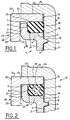
- la figure 1 représente un réservoir présentant un joint de bonde qui est torique, dans le cas d'un logement au minimum de la tolérance ;
- la figure 2 représente un réservoir présentant un joint de bonde selon l'invention, dans le cas d'un logement au minimum de la tolérance ;
- la figure 3a représente en coupe un joint selon l'invention ;
- la figure 3b représente la superposition des profils d'un joint torique de diamètre nominal correspondant à un logement de réservoir, et d'un joint selon l'invention correspondant au même logement ;
- les figures 4a et 4b illustrent le problème du roulement d'un joint torique, et la figure 5 illustre le comportement d'un joint selon un mode de réalisation particulièrement avantageux de l'invention ;
- la figure 6 représente en coupe une variante préférée du joint représenté à la figure 3a.
- Figure 1 shows a tank having a drain seal which is O-ring, in the case of a housing at the minimum tolerance;
- FIG. 2 represents a tank presenting a drain joint according to the invention, in the case of a housing at the minimum of the tolerance;
- Figure 3a shows in section a seal according to the invention;
- FIG. 3b represents the superposition of the profiles of an O-ring of nominal diameter corresponding to a tank housing, and of a seal according to the invention corresponding to the same housing;
- Figures 4a and 4b illustrate the problem of rolling an O-ring, and Figure 5 illustrates the behavior of a seal according to a particularly advantageous embodiment of the invention;
- 6 shows in section a preferred variant of the seal shown in Figure 3a.
Comme le montrent les figures 1 et 2, un réservoir en matière plastique, désigné par le repère général 1, par exemple un réservoir en polyéthylène, présente un col 2 de forme générale cylindrique présentant une surface cylindrique externe 3 pourvue d'un filetage 6 en vue du vissage d'un écrou 10 pourvu sur sa face cylindrique interne 16 d'un filetage complémentaire 12.As shown in FIGS. 1 and 2, a plastic tank, designated by the general reference 1, for example a polyethylene tank, has a
Le col 2 présente un bord interne 4 présentant une face supérieure annulaire plane 5. Une région cylindrique 7 bordant la face 5 prolonge vers le haut le bord interne 4. La région 7 a une section inférieure à celle du col 2. Elle présente un bord supérieur 9 et une face cylindrique externe 8 qui jouxte la face plane 5 et une face cylindrique interne 17. Une platine 20 présente en coupe un profil en L à deux branches, à savoir une branche 23 ayant une face supérieure annulaire 24 et une face inférieure annulaire 25 et une branche 21 disposée perpendiculairement à la branche 23 et ayant une face cylindrique externe 22 et une face cylindrique interne 28.The
La platine 20 est bloquée par l'écrou 10 qui vient en appui par sa face 15 sur la face 23 de la platine 20, de manière que la face 25 s'appuie sur le bord supérieur 9 de la région 7. Les faces annulaires 5 et 25 et les faces cylindriques 8 et 16 définissent un logement pour un joint.The
Les dimensions d'un joint doivent être choisies pour que son taux de serrage soit compris entre 5% et 25% selon que les tolérances du logement sont maximales ou minimales.The dimensions of a joint must be chosen so that its tightening rate is between 5% and 25% depending on whether the tolerances of the housing are maximum or minimum.
Etant donné la dispersion des cotes qui est due aux matériaux employés dans l'application envisagée (réservoirs de carburant), le volume du logement ou gorge tend à être trop petit. En effet, la dispersion des cotes implique la mise en oeuvre d'un joint torique 30 de diamètre au moins égal à environ 5 mm (pour respecter la condition précitée relative au taux de serrage) et qui présente un bord d'appui supérieur, un bord d'appui inférieur, un bord d'appui extérieur et un bord d'appui intérieur, ces bords étant ponctuels avant la mise en compression du joint, mais tendant à s'aplatir ensuite. Dans le cas où les tolérances sont à leur valeur minimale, le joint torique 30 occupe toute la surface du logement et tend à déformer la région 7 (fig. 1) comme indiqué par la flèche F. La région 7 n'est plus parallèle à l'axe du col 2, et le bord 9 est écarté de la face 25. Ceci est préjudiciable à la tenue mécanique et à l'étanchéité du dispositif. En outre, le montage et le, démontage sont rendus malaisés.Given the dispersion of the dimensions which is due to the materials used in the envisaged application (fuel tanks), the volume of the housing or groove tends to be too small. Indeed, the dispersion of the dimensions implies the implementation of an O-
La mise en oeuvre d'un joint 40 dont le profil est allongé selon l'axe du col 2 permet de remédier au moins en grande partie à cet inconvénient, comme le montre la figure 2.The use of a
Le joint 40, dont un mode de réalisation particulièrement avantageux est représenté à la figure 3a, présente une hauteur H prise parallèlement à l'axe du col 2, et une largeur maximale L prise perpendiculairement à ce même axe, avec H>L.The
Il comporte une face interne cylindrique 41 en contact avec la face 8, deux faces planes, inférieure 42 en contact avec la face 5 et supérieure 43 en contact avec la face 25. La région 46 est convexe et présente une partie centrale 47 qui se raccorde en 48 avec les faces 42 et 43. Les faces 41 et 42 sont raccordées entre elles par une région convexe 44, et les faces 41 et 43 sont raccordées entre elles par une région convexe 45.It has a cylindrical
La présente d'une face cylindrique plate 41 permet d'éviter le phénomène de roulement et d'extraction du joint 40. Ce phénomène est illustré aux figures 4a et 4b dans le cas d'un joint torique 30. Si le joint torique 30 est monté avec une extension suffisante pour son maintien dans la gorge, il tend alors à rouler sur lui-même dans le sens de la flèche F lors de sa mise en place. Il tend de ce fait à revenir à sa position initiale sous l'effet de l'élasticité en roulant en sens contraire dans le sens de la flèche F' (fig. 4b). Avec un joint 40 de forme allongée (H > L), présentant une face cylindrique 41, le phénomène de roulement est évité, le joint 40 étant mis en place en extension autour de la face 8.The presence of a flat
La mise en oeuvre d'un joint 40 permet en outre de réduire le volume de caoutchouc utilisé, qui est en général du fluocarbone, matériau coûteux compatible avec les carburants.The use of a
La largeur L (L < H) et la forme de la région convexe 46 sont choisies de manière à éviter que les vapeurs de carburant ne traversent le joint 40 par perméabilité.The width L (L <H) and the shape of the convex
Le profil du joint 40 est de préférence tel qu'il s'inscrive dans le profil du joint torique 30, c'est-à-dire que H = D et L < D.The profile of the
EXEMPLE pour une gorge 8 de diamètre 126 mm.
- a) JOINT 30 : diamètre intérieur ⌀ = 125 mm (mauvais maintien)
D = 5 mm - b) JOINT 40 : ⌀ = 123 mm (meilleur maintien)
H = 5 mm
L = 4 mm
La figure 6 représente une variante du joint de la figure 3a, ayant une géométrie permettant de diminuer la pression axiale du joint sur son diamètre intérieur, et permettant en conséquence de réduire les déformations résiduelles du col du réservoir en réduisant les contraintes du joint 40 sur le col du réservoir, notamment dans la région 29 située au voisinage du diamètre intérieur du logement du joint (voir fig.1). Ce résultat est obtenu à l'aide d'au moins une région 50 de forme aplatie et de préférence plate, qui raccorde les faces 41 et 42 d'une part, et/ou les faces 41 et 43 d'autre part, éventuellement par l'intermédiaire de régions convexes 44' et 45', et qui diminuent la hauteur du joint au fur et à mesure que l'on se rapproche de laface interne 41 du joint.
- a) JOINT 30: internal diameter ⌀ = 125 mm (poor support)
D = 5 mm - b) JOINT 40: ⌀ = 123 mm (better support)
H = 5 mm
L = 4 mm
FIG. 6 represents a variant of the seal of FIG. 3a, having a geometry making it possible to reduce the axial pressure of the seal over its internal diameter, and consequently making it possible to reduce the residual deformations of the neck of the reservoir by reducing the stresses of theseal 40 on the neck of the tank, especially inregion 29 located near the inside diameter of the seal housing (see fig. 1). This result is obtained using at least oneregion 50 of flattened and preferably flat shape, which connects thefaces faces internal face 41 of the joint.
Claims (12)
Priority Applications (1)
| Application Number | Priority Date | Filing Date | Title |
|---|---|---|---|
| US08/868,613 US5913441A (en) | 1996-06-04 | 1997-06-03 | Fuel tank having a body of plastics material and a sealing gasket |
Applications Claiming Priority (2)
| Application Number | Priority Date | Filing Date | Title |
|---|---|---|---|
| FR9606860A FR2749227B1 (en) | 1996-06-04 | 1996-06-04 | FUEL TANK HAVING A PLASTIC BODY AND A SEAL |
| FR9606860 | 1996-06-04 |
Publications (2)
| Publication Number | Publication Date |
|---|---|
| EP0811519A1 true EP0811519A1 (en) | 1997-12-10 |
| EP0811519B1 EP0811519B1 (en) | 2001-07-25 |
Family
ID=9492691
Family Applications (1)
| Application Number | Title | Priority Date | Filing Date |
|---|---|---|---|
| EP19970401041 Expired - Lifetime EP0811519B1 (en) | 1996-06-04 | 1997-05-09 | Fuel tank made of plastic and sealing joint |
Country Status (4)
| Country | Link |
|---|---|
| EP (1) | EP0811519B1 (en) |
| DE (1) | DE69705773T2 (en) |
| ES (1) | ES2162207T3 (en) |
| FR (1) | FR2749227B1 (en) |
Cited By (2)
| Publication number | Priority date | Publication date | Assignee | Title |
|---|---|---|---|---|
| EP2381143A1 (en) | 2010-04-26 | 2011-10-26 | Le Joint Francais | Watertight seal, tank including such a seal and use of said seal |
| CN109305328A (en) * | 2018-11-12 | 2019-02-05 | 中国商用飞机有限责任公司北京民用飞机技术研究中心 | A kind of wing box and aircraft |
Citations (4)
| Publication number | Priority date | Publication date | Assignee | Title |
|---|---|---|---|---|
| US3322432A (en) * | 1963-10-29 | 1967-05-30 | Soguel Rene | Watertight sealing means for a control device extending through the casing of an instrument |
| GB1146768A (en) * | 1967-01-16 | 1969-03-26 | Carlo Tondato | Sealing ring, more particularly for machine parts |
| FR2596333A1 (en) * | 1986-03-25 | 1987-10-02 | Renault | Device for mounting a gauge, in a sealed fashion, on a fuel tank |
| EP0379401A1 (en) * | 1989-01-20 | 1990-07-25 | Le Joint Francais Snc | Mounting device sealing ring for conduits of metal or plastics |
-
1996
- 1996-06-04 FR FR9606860A patent/FR2749227B1/en not_active Expired - Fee Related
-
1997
- 1997-05-09 DE DE1997605773 patent/DE69705773T2/en not_active Expired - Lifetime
- 1997-05-09 EP EP19970401041 patent/EP0811519B1/en not_active Expired - Lifetime
- 1997-05-09 ES ES97401041T patent/ES2162207T3/en not_active Expired - Lifetime
Patent Citations (4)
| Publication number | Priority date | Publication date | Assignee | Title |
|---|---|---|---|---|
| US3322432A (en) * | 1963-10-29 | 1967-05-30 | Soguel Rene | Watertight sealing means for a control device extending through the casing of an instrument |
| GB1146768A (en) * | 1967-01-16 | 1969-03-26 | Carlo Tondato | Sealing ring, more particularly for machine parts |
| FR2596333A1 (en) * | 1986-03-25 | 1987-10-02 | Renault | Device for mounting a gauge, in a sealed fashion, on a fuel tank |
| EP0379401A1 (en) * | 1989-01-20 | 1990-07-25 | Le Joint Francais Snc | Mounting device sealing ring for conduits of metal or plastics |
Cited By (4)
| Publication number | Priority date | Publication date | Assignee | Title |
|---|---|---|---|---|
| EP2381143A1 (en) | 2010-04-26 | 2011-10-26 | Le Joint Francais | Watertight seal, tank including such a seal and use of said seal |
| FR2959293A1 (en) * | 2010-04-26 | 2011-10-28 | Joint Francais | SEAL, TANK COMPRISING SUCH A SEAL AND USE OF SUCH A SEAL |
| CN109305328A (en) * | 2018-11-12 | 2019-02-05 | 中国商用飞机有限责任公司北京民用飞机技术研究中心 | A kind of wing box and aircraft |
| CN109305328B (en) * | 2018-11-12 | 2024-01-16 | 中国商用飞机有限责任公司北京民用飞机技术研究中心 | Wing box and aircraft |
Also Published As
| Publication number | Publication date |
|---|---|
| DE69705773T2 (en) | 2002-05-23 |
| FR2749227A1 (en) | 1997-12-05 |
| DE69705773D1 (en) | 2001-08-30 |
| FR2749227B1 (en) | 1998-09-11 |
| ES2162207T3 (en) | 2001-12-16 |
| EP0811519B1 (en) | 2001-07-25 |
Similar Documents
| Publication | Publication Date | Title |
|---|---|---|
| EP2648988B1 (en) | Liquid container having protection device | |
| CA2945762C (en) | Sealed nut | |
| FR2986598A1 (en) | SEAL | |
| EP0635651B1 (en) | Bearing arrangement for a rotating shaft from a screen wiper drive mechanism | |
| FR2879710A1 (en) | SLIDING RING SEALANT, ESPECIALLY FOR AUTOMOTIVE VEHICLE REFRIGERANT PUMPS | |
| FR2743040A1 (en) | WINDSCREEN WIPER MECHANISM INCLUDING ADVANCED GUIDING AND SEALING MEANS FOR THE CROSSING OF A SHEET BY A DRIVE SHAFT | |
| EP0140171A1 (en) | Sealing ring for cast iron pipe couplings | |
| EP0737830A1 (en) | Seal and method for mounting | |
| EP2381143B1 (en) | Watertight seal, tank including such a seal and use of said seal | |
| FR2504231A3 (en) | SEAL COMPRISING TWO LEVERS, ONE OF WHICH IS AXIAL AND THE OTHER RADIAL, AND A LABYRINTH | |
| EP0811519B1 (en) | Fuel tank made of plastic and sealing joint | |
| FR2554543A1 (en) | Connection for rapidly fitting a pipework pipe into a tapped hole. | |
| FR2938038A1 (en) | SEALING ELEMENT WITHOUT RETENTION AREA AND CONNECTING DEVICE COMPRISING SUCH A SEALING ELEMENT | |
| FR2952854A1 (en) | WASTE COLLECTION BIN WITH A NOSE WHEEL | |
| FR2945088A1 (en) | Blind countersunk nut system, has non- threaded skirt supporting quasi-radial face of support crown adjacent to crimping zone, and barrel constituting crimping zone on side of head and support crown of nut | |
| FR2946411A1 (en) | Sealing element i.e. joint, for pipe end connector in liquid food product transporting circuit, has annular part elastically deformable under action of axial constraints, and sidewalls with reinforcement integrated to annular part | |
| WO1998023505A1 (en) | Device and method for fixing a metering member in a container containing a product to be dispensed | |
| EP0202156A1 (en) | Anular sealing device, especially for valves or taps | |
| FR2694348A1 (en) | Radial clamping device for a pipe and connection piece comprising this device. | |
| FR2687443A1 (en) | ELASTIC ANNULAR JOINT. | |
| EP0710308A1 (en) | Device for anchoring a resilient rail clip | |
| EP1220801A1 (en) | Member for fixing a fluid product dispensing device and dispenser comprising same | |
| FR2702819A1 (en) | Gasket for quick-connect coupling with claw or clamp. | |
| EP0546911B1 (en) | Sealing ring and fuel tank | |
| FR3124783A1 (en) | Support ring assembly for railway axles |
Legal Events
| Date | Code | Title | Description |
|---|---|---|---|
| PUAI | Public reference made under article 153(3) epc to a published international application that has entered the european phase |
Free format text: ORIGINAL CODE: 0009012 |
|
| AK | Designated contracting states |
Kind code of ref document: A1 Designated state(s): BE DE ES FR GB IT LU NL SE |
|
| 17P | Request for examination filed |
Effective date: 19980410 |
|
| 17Q | First examination report despatched |
Effective date: 19990720 |
|
| GRAG | Despatch of communication of intention to grant |
Free format text: ORIGINAL CODE: EPIDOS AGRA |
|
| GRAG | Despatch of communication of intention to grant |
Free format text: ORIGINAL CODE: EPIDOS AGRA |
|
| GRAH | Despatch of communication of intention to grant a patent |
Free format text: ORIGINAL CODE: EPIDOS IGRA |
|
| GRAH | Despatch of communication of intention to grant a patent |
Free format text: ORIGINAL CODE: EPIDOS IGRA |
|
| GRAA | (expected) grant |
Free format text: ORIGINAL CODE: 0009210 |
|
| AK | Designated contracting states |
Kind code of ref document: B1 Designated state(s): BE DE ES FR GB IT LU NL SE |
|
| PG25 | Lapsed in a contracting state [announced via postgrant information from national office to epo] |
Ref country code: NL Free format text: LAPSE BECAUSE OF FAILURE TO SUBMIT A TRANSLATION OF THE DESCRIPTION OR TO PAY THE FEE WITHIN THE PRESCRIBED TIME-LIMIT Effective date: 20010725 |
|
| REF | Corresponds to: |
Ref document number: 69705773 Country of ref document: DE Date of ref document: 20010830 |
|
| PG25 | Lapsed in a contracting state [announced via postgrant information from national office to epo] |
Ref country code: SE Free format text: LAPSE BECAUSE OF FAILURE TO SUBMIT A TRANSLATION OF THE DESCRIPTION OR TO PAY THE FEE WITHIN THE PRESCRIBED TIME-LIMIT Effective date: 20011025 |
|
| GBT | Gb: translation of ep patent filed (gb section 77(6)(a)/1977) |
Effective date: 20011025 |
|
| REG | Reference to a national code |
Ref country code: ES Ref legal event code: FG2A Ref document number: 2162207 Country of ref document: ES Kind code of ref document: T3 |
|
| REG | Reference to a national code |
Ref country code: GB Ref legal event code: IF02 |
|
| NLV1 | Nl: lapsed or annulled due to failure to fulfill the requirements of art. 29p and 29m of the patents act | ||
| PG25 | Lapsed in a contracting state [announced via postgrant information from national office to epo] |
Ref country code: LU Free format text: LAPSE BECAUSE OF NON-PAYMENT OF DUE FEES Effective date: 20020509 |
|
| PLBE | No opposition filed within time limit |
Free format text: ORIGINAL CODE: 0009261 |
|
| STAA | Information on the status of an ep patent application or granted ep patent |
Free format text: STATUS: NO OPPOSITION FILED WITHIN TIME LIMIT |
|
| 26N | No opposition filed | ||
| PGFP | Annual fee paid to national office [announced via postgrant information from national office to epo] |
Ref country code: ES Payment date: 20120525 Year of fee payment: 16 |
|
| PGFP | Annual fee paid to national office [announced via postgrant information from national office to epo] |
Ref country code: GB Payment date: 20130521 Year of fee payment: 17 |
|
| PGFP | Annual fee paid to national office [announced via postgrant information from national office to epo] |
Ref country code: IT Payment date: 20130527 Year of fee payment: 17 Ref country code: BE Payment date: 20130521 Year of fee payment: 17 |
|
| GBPC | Gb: european patent ceased through non-payment of renewal fee |
Effective date: 20140509 |
|
| PG25 | Lapsed in a contracting state [announced via postgrant information from national office to epo] |
Ref country code: IT Free format text: LAPSE BECAUSE OF NON-PAYMENT OF DUE FEES Effective date: 20140509 |
|
| REG | Reference to a national code |
Ref country code: FR Ref legal event code: PLFP Year of fee payment: 19 |
|
| PG25 | Lapsed in a contracting state [announced via postgrant information from national office to epo] |
Ref country code: GB Free format text: LAPSE BECAUSE OF NON-PAYMENT OF DUE FEES Effective date: 20140509 |
|
| REG | Reference to a national code |
Ref country code: ES Ref legal event code: FD2A Effective date: 20150626 |
|
| PG25 | Lapsed in a contracting state [announced via postgrant information from national office to epo] |
Ref country code: ES Free format text: LAPSE BECAUSE OF NON-PAYMENT OF DUE FEES Effective date: 20140510 |
|
| REG | Reference to a national code |
Ref country code: FR Ref legal event code: PLFP Year of fee payment: 20 |
|
| PGFP | Annual fee paid to national office [announced via postgrant information from national office to epo] |
Ref country code: DE Payment date: 20160520 Year of fee payment: 20 |
|
| PGFP | Annual fee paid to national office [announced via postgrant information from national office to epo] |
Ref country code: FR Payment date: 20160531 Year of fee payment: 20 |
|
| REG | Reference to a national code |
Ref country code: DE Ref legal event code: R071 Ref document number: 69705773 Country of ref document: DE |
|
| PG25 | Lapsed in a contracting state [announced via postgrant information from national office to epo] |
Ref country code: BE Free format text: LAPSE BECAUSE OF NON-PAYMENT OF DUE FEES Effective date: 20140531 |