EP0810812B1 - Ensemble microphone différentiel avec suppression passive des résonances - Google Patents
Ensemble microphone différentiel avec suppression passive des résonances Download PDFInfo
- Publication number
- EP0810812B1 EP0810812B1 EP97303413A EP97303413A EP0810812B1 EP 0810812 B1 EP0810812 B1 EP 0810812B1 EP 97303413 A EP97303413 A EP 97303413A EP 97303413 A EP97303413 A EP 97303413A EP 0810812 B1 EP0810812 B1 EP 0810812B1
- Authority
- EP
- European Patent Office
- Prior art keywords
- conduits
- microphone
- branch
- acoustic
- neck
- Prior art date
- Legal status (The legal status is an assumption and is not a legal conclusion. Google has not performed a legal analysis and makes no representation as to the accuracy of the status listed.)
- Expired - Lifetime
Links
- 230000001629 suppression Effects 0.000 title 1
- 210000003739 neck Anatomy 0.000 description 10
- 238000010586 diagram Methods 0.000 description 4
- 230000000694 effects Effects 0.000 description 3
- 238000001914 filtration Methods 0.000 description 3
- 230000005540 biological transmission Effects 0.000 description 2
- 238000013016 damping Methods 0.000 description 2
- 238000001746 injection moulding Methods 0.000 description 2
- 238000004519 manufacturing process Methods 0.000 description 2
- 239000000463 material Substances 0.000 description 2
- 238000000034 method Methods 0.000 description 2
- 230000010363 phase shift Effects 0.000 description 2
- 101000713585 Homo sapiens Tubulin beta-4A chain Proteins 0.000 description 1
- 102100036788 Tubulin beta-4A chain Human genes 0.000 description 1
- 239000002775 capsule Substances 0.000 description 1
- 230000001419 dependent effect Effects 0.000 description 1
- 230000009699 differential effect Effects 0.000 description 1
- 239000011888 foil Substances 0.000 description 1
- 238000003801 milling Methods 0.000 description 1
- 238000000465 moulding Methods 0.000 description 1
- 230000000149 penetrating effect Effects 0.000 description 1
- 230000000737 periodic effect Effects 0.000 description 1
- 230000021715 photosynthesis, light harvesting Effects 0.000 description 1
Images


Classifications
-
- H—ELECTRICITY
- H04—ELECTRIC COMMUNICATION TECHNIQUE
- H04R—LOUDSPEAKERS, MICROPHONES, GRAMOPHONE PICK-UPS OR LIKE ACOUSTIC ELECTROMECHANICAL TRANSDUCERS; DEAF-AID SETS; PUBLIC ADDRESS SYSTEMS
- H04R1/00—Details of transducers, loudspeakers or microphones
- H04R1/20—Arrangements for obtaining desired frequency or directional characteristics
- H04R1/22—Arrangements for obtaining desired frequency or directional characteristics for obtaining desired frequency characteristic only
- H04R1/28—Transducer mountings or enclosures modified by provision of mechanical or acoustic impedances, e.g. resonator, damping means
- H04R1/2869—Reduction of undesired resonances, i.e. standing waves within enclosure, or of undesired vibrations, i.e. of the enclosure itself
-
- H—ELECTRICITY
- H04—ELECTRIC COMMUNICATION TECHNIQUE
- H04M—TELEPHONIC COMMUNICATION
- H04M1/00—Substation equipment, e.g. for use by subscribers
- H04M1/02—Constructional features of telephone sets
- H04M1/19—Arrangements of transmitters, receivers, or complete sets to prevent eavesdropping, to attenuate local noise or to prevent undesired transmission; Mouthpieces or receivers specially adapted therefor
-
- H—ELECTRICITY
- H04—ELECTRIC COMMUNICATION TECHNIQUE
- H04R—LOUDSPEAKERS, MICROPHONES, GRAMOPHONE PICK-UPS OR LIKE ACOUSTIC ELECTROMECHANICAL TRANSDUCERS; DEAF-AID SETS; PUBLIC ADDRESS SYSTEMS
- H04R1/00—Details of transducers, loudspeakers or microphones
- H04R1/20—Arrangements for obtaining desired frequency or directional characteristics
- H04R1/32—Arrangements for obtaining desired frequency or directional characteristics for obtaining desired directional characteristic only
- H04R1/34—Arrangements for obtaining desired frequency or directional characteristics for obtaining desired directional characteristic only by using a single transducer with sound reflecting, diffracting, directing or guiding means
- H04R1/342—Arrangements for obtaining desired frequency or directional characteristics for obtaining desired directional characteristic only by using a single transducer with sound reflecting, diffracting, directing or guiding means for microphones
-
- H—ELECTRICITY
- H04—ELECTRIC COMMUNICATION TECHNIQUE
- H04R—LOUDSPEAKERS, MICROPHONES, GRAMOPHONE PICK-UPS OR LIKE ACOUSTIC ELECTROMECHANICAL TRANSDUCERS; DEAF-AID SETS; PUBLIC ADDRESS SYSTEMS
- H04R1/00—Details of transducers, loudspeakers or microphones
- H04R1/20—Arrangements for obtaining desired frequency or directional characteristics
- H04R1/32—Arrangements for obtaining desired frequency or directional characteristics for obtaining desired directional characteristic only
- H04R1/34—Arrangements for obtaining desired frequency or directional characteristics for obtaining desired directional characteristic only by using a single transducer with sound reflecting, diffracting, directing or guiding means
- H04R1/38—Arrangements for obtaining desired frequency or directional characteristics for obtaining desired directional characteristic only by using a single transducer with sound reflecting, diffracting, directing or guiding means in which sound waves act upon both sides of a diaphragm and incorporating acoustic phase-shifting means, e.g. pressure-gradient microphone
-
- H—ELECTRICITY
- H04—ELECTRIC COMMUNICATION TECHNIQUE
- H04R—LOUDSPEAKERS, MICROPHONES, GRAMOPHONE PICK-UPS OR LIKE ACOUSTIC ELECTROMECHANICAL TRANSDUCERS; DEAF-AID SETS; PUBLIC ADDRESS SYSTEMS
- H04R2499/00—Aspects covered by H04R or H04S not otherwise provided for in their subgroups
- H04R2499/10—General applications
- H04R2499/11—Transducers incorporated or for use in hand-held devices, e.g. mobile phones, PDA's, camera's
Definitions
- Second older differential (SOD) microphones have long been recognized for their superior noise cancelling performance relative to first order differential (FOD) or zero order differential (pressure) microphones.
- Realizations of a working SOD microphone were described in W. A. Beaverson and A. M. Wiggins, "A Second Order Gradient Noise Cancelling Microphone Using a Single Diaphragm,” J. Acoust. Soc. Am., 22 (1950), pp. 592-601 , and A. J. Brouns, "Second Order Gradient Noise Cancelling Microphone,” IEEE International Conference on Acoustics, Speech and Signal Processing, (March 1981), pp. 786-789 .
- acoustic ports and ducts within an enclosure are used to sample the ambient pressure field and guide the acoustic energy to the sensing element which could be, for example, a moving coil, a piezoelectric transducer or a foil electret diaphragm.
- One way to reduce, or even eliminate, the need for compensating circuits is to modify the acoustic ducting to make it acoustically filter the guided acoustic field, and thus passively compensate for undesired acoustic resonances in a manner which preserves the second order differential properties of the microphone.
- our invention involves a SOD microphone of the kind in which a FOD microphone element communicates with respective front and rear chambers, two ports communicate with the front chamber via front conduits, and two ports communicate with the rear chamber via rear conduits.
- our microphone further comprises first and second side chambers for dissipating acoustic energy of undesired resonances of the microphone.
- the first side chamber communicates with the front conduits, and the second side chamber communicates with the rear conduits.
- each of the side chambers comprises a branch conduit approximately equal in length to one-quarter wavelength of an undesired resonance. In certain embodiments, this length includes a small neck joining the branch conduit to its corresponding front or rear conduits.
- each of the side chambers comprises a Helmholtz resonator. Each Helmholtz resonator, in turn, comprises a short branch conduit leading to a resonant chamber having a prescribed volume.
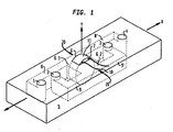
- our microphone includes an enclosure 5 having a cavity 6 into which a commercially available FOD microphone element 11, such as an electret microphone element, is readily inserted without the need for penetrating the casing of the microphone element as provided by the commercial supplier.
- a commercially available FOD microphone element 11 such as an electret microphone element
- a front cavity portion 6.1 referred to as the front chamber, is defined adjacent to the front side of the FOD microphone diaphragm (the diaphragm is contained within element 11, and is not shown in the figure), and similarly, a rear cavity portion 6.2, referred to as the rear chamber, is defined adjacent the rear side of the diaphragm.
- a pair of conduits 8, 8' referred to as "front conduits," conduct acoustic energy from first port 1 and fourth port 4, respectively, to the front chamber 6.1.
- a pair of rear conduits 9, 9' conduct acoustic energy from second port 2 and third port 3, respectively, to the rear chamber 6.2.
- the four ports 1 - 4 are similar in their acoustic characteristics and are, typically, of approximately equal dimensions.
- the four ports will typically lie in a common plane, and they will typically line up along a common centerline.
- the distance between the first and second ports is desirably made the same, or nearly the same, as the distance between the third and fourth ports.
- the two front conduits 8, 8', and the two rear conduits 9, 9' are all desirably made with equivalent lengths and equivalent cross sectional areas, and they are desirably formed to meet their respective cavities (i.e., front chamber 6.1 and rear chamber 6.2) in an acoustically equivalent manner
- FIG. 1 Also shown in FIG. 1 is a pair 10 of electrical leads connected to microphone element 11.
- One readily manufacturable embodiment of such a microphone is assembled from laminar plates, for example, plates of a polymeric material formed by injection molding.
- laminar plates for example, plates of a polymeric material formed by injection molding.
- the various cavities and conduits described above, as well as those to be described below, are readily provided as channels formed in these laminar plates during the molding process, or, e.g., by stamping or milling.
- FIG. 2A also depicts some of the common features referred to above. However, for simplicity of presentation, the front conduits 8, 8', and the rear conduits 9, 9', are shown only in abbreviated form in FIG. 2A , and the ports 1 - 4 are not shown.
- FIG. 2A Depicted in FIG. 2A are two further conduits 21, 21', which we refer to hereinafter as the "front branch conduit” and the “rear branch conduit”, respectively.
- the pair of front conduits 8, 8' has a common sidewall region adjacent front chamber 6.1, on the side of the conduits lying distal the microphone element.
- the pair of rear conduits 9, 9' has a common sidewall region adjacent rear chamber 6.2, on the side of those conduits lying distal the microphone element.
- the front branch conduit 21 is formed so as to intersect the sidewall of the front conduits in this common region thereof.
- the rear branch conduit 21' is formed so as to intersect the sidewall of the rear conduits in this common region thereof.
- the front and rear branch conduits are desirably of equal, or nearly equal, lengths and cross sectional areas, and they desirably intersect the respective sidewall regions in an acoustically equivalent manner.
- the length of each branch conduit is approximately one quarter acoustic wavelength at a resonant frequency to be reduced or eliminated.
- this resonant frequency will be a fundamental mode of the front and rear conduits, i.e., a resonance having a wavelength twice the length of the front or rear conduit.
- the length of each branch conduit is desirably made equal, or nearly equal, to half the length of its corresponding front or rear conduit. (In this regard, two lengths are "nearly equal” if they differ by no more than one-tenth the guided wavelength of some acoustic tone within the passband of the microphone.)
- each branch conduit ends, distal its intersection with the corresponding conduit sidewall, in an acoustically rigid termination within enclosure 5.
- acoustic waves at the resonant frequency that propagate into a branch conduit will reflect from the rigid termination and return to the point of intersection with the corresponding front or rear conduits with a net phase shift of 180°. Because of this phase shift, the reflected wave will destructively interfere with the acoustic waves in the corresponding front or rear conduit.
- one such feature is a set of serrations 23, 23' on the inner sidewall surface of each of the branch conduits.
- another such feature is a short and thin neck 25, 25' joining each branch conduit to its corresponding front or rear conduits. (The length of such a neck is preferably no more than one-tenth the resonant wavelength.) Any such energy-dissipating feature should act in an acoustically equivalent manner for both of the branch conduits.
- An appropriate adjustment of the amount of acoustic dissipation in the branch conduits can lead to substantially resonance-free microphone output over the voice frequency band.
- each branch conduit is not required to be straight, nor are they required to be oriented in any particular direction.
- each branch conduit should present the same, or nearly the same, acoustic impedance to its corresponding front or rear conduits. For this reason, it is desirable for each branch conduit to have the same cross-sectional area. In cases in which this area is not constant, it is desirable to have the same variation, in both branch conduits, of cross-sectional area as a function of longitudinal position within the conduit.
- the acoustic system associated with each branch conduit presents an acoustic branch impedance, Z b , to the acoustic wave conducted from each port to the microphone diaphragm.
- Z b acoustic branch impedance
- f is the acoustic frequency (in Hz)
- ⁇ is the angular frequency 2 ⁇ f
- L/2 is the distance from each port to the microphone diaphragm
- k is the acoustic wavenumber 2 ⁇ ⁇ ⁇ ( ⁇ is the acoustic wavelength)
- each of the branch conduits ends at an acoustically rigid termination.
- R b ⁇ 1 ⁇ 0 ⁇ c S b ⁇ ⁇ L sin 2 2 ⁇ ⁇ L ⁇ + ⁇ L 2 ⁇ cos 2 2 ⁇ ⁇ L ⁇ , where S b is the branch cross sectional area.
- the amount of dissipation of acoustic energy in the branch conduits depends upon the branch-conduit cross sectional area. This area is readily varied along the length of the conduit. Manufacturing processes are available that can reproduceably provide such variation. For example, techniques of injection molding are readily applied to provide such variation in conduits formed within a base of polymeric material.
- Such variations of cross-sectional area are readily tailored to provide a desired resistive impedance R b1 and, concomitantly, a desired amount of dissipation.
- a serrated pattern such as patterns 23 and 23' of FIG. 2A
- S b is readily provided by periodically varying S b between a higher value S 1 and a lower value S 0 at a spatial period l s .
- a sawtooth pattern of serrations is preferable, since the sharp vertices of such a pattern are associated with high viscous losses that are helpful for dissipating acoustic energy.
- an alternative feature for dissipating acoustic energy is a short and narrow neck 25,25' for acoustically connecting each branch conduit 24, 24' to its corresponding front or rear conduits.
- the length l ss , width w, and height t of each neck are all desirably not more than one-tenth the wavelength of the resonance to be dissipated.
- the length of the neck is preferably included in the total length of the corresponding branch conduit.
- the cross-sectional area of the neck should be smaller than the cross-sectional area of the main portion of the corresponding branch conduit, in order to provide an acoustic impedance at the resulting constriction, to dissipate acoustic energy. It is advantageous for ease of fabrication, but not essential, for the branch conduits 24, 24' to have a cross sectional area S b equal to the cross sectional area S of the front and rear conduits 8, 8', 9, 9'.
- FIG. 5 Plotted in FIG. 5 is the theoretically predicted frequency response of the transfer function K( ⁇ ) for the branch conduits and necks of FIG. 2B with the following parameter values:
- each branch conduit 26, 26' is made no more than about one-tenth the wavelength associated with the acoustic resonance to be dissipated
- the far end of each branch conduit i.e., the end distal the front or rear conduits
- a Helmholtz resonator is an acoustical system comprising a rigid enclosure of a given volume, communicating with the external medium through a small opening.
- acoustical behavior of such a system can be described in terms of a simple mechanical oscillator. having a resonant Helmholtz resonators are described, e.g., in Kinsler et al., cited above.
- This embodiment of the invention makes use of the fact that a Helmholtz resonator connected to the sidewall of a duct that is transporting acoustic energy will cause attenuation of the acoustic energy over a band of frequencies centered around the resonant frequency of the resonator.
- the volumes of the front and rear Helmholtz resonators, and the cross sectional areas and lengths of the connecting conduits can be chosen such that the resulting microphone will have no substantial resonant response for, e.g., frequencies below 4000 Hz.
- a frequency response will be provided that substantially resembles the responses of typical prior-art SOD microphones that perform electronic differencing of the responses from two appropriately spaced FOD microphones.
- cavities 27, 27' and of the small, connecting branch conduits 26, 26' are not critical.
- the acoustic impedance presented by the front Helmholtz resonator (i.e., the front resonant cavity in combination with the front branch conduit) to the front conduits should be the same, or nearly the same, as the acoustic impedance presented by the rear Helmholtz resonator to the rear conduits.
- branch conduits 26,26' each have length l h , diameter d, and cross-sectional area S b . (For purposes of the following theoretical analysis, the branch conduits are circular in cross section.)
- cavities 27,27' each have volume V. These respective cavities are conveniently made in the same shape, although this is not essential.
- Z b2 of each Helmholtz resonator is theoretically given by the following expression (the numeral "2" in the subscript denotes that this is the second illustrative embodiment of the invention):
- Z b ⁇ 2 7.58 ⁇ 10 - 4 l h d 4 + i ⁇ ⁇ 0 ⁇ c 2 ⁇ V - ⁇ 0 ⁇ ⁇ ⁇ l h + 0.85 ⁇ d S b .
Landscapes
- Health & Medical Sciences (AREA)
- Otolaryngology (AREA)
- Physics & Mathematics (AREA)
- Engineering & Computer Science (AREA)
- Acoustics & Sound (AREA)
- Signal Processing (AREA)
- Obtaining Desirable Characteristics In Audible-Bandwidth Transducers (AREA)
- Electrostatic, Electromagnetic, Magneto- Strictive, And Variable-Resistance Transducers (AREA)
- Soundproofing, Sound Blocking, And Sound Damping (AREA)
Claims (7)
- Appareil comportant un microphone SOD (microphone différentiel du deuxième ordre) du type dans lequel un élément de microphone FOD (microphone différentiel du premier ordre) (11) communique avec des chambres avant (6.1') et arrière (6.2) respectives, ladite chambre avant communiquant avec un premier et un quatrième ports respectifs (1, 4) par le biais de deux conduits avant respectifs (8, 8'), et ladite chambre arrière communiquant avec un second et un troisième ports respectifs (2, 3) par le biais de deux conduits arrière respectifs (9, 9'), caractérisé en ce quea) ledit microphone SOD comporte par ailleurs une première et une seconde chambres latérales (21, 21') permettant de dissiper l'énergie acoustique de résonances indésirables du microphone ;b) la première chambre latérale communique avec les conduits avant ; etc) la seconde chambre latérale communique avec les conduits arrière.
- Appareil selon la revendication 1, dans lequel chacune des chambres latérales comporte un conduit dérivé (25, 25') approximativement égal en longueur à un quart de longueur d'onde d'une résonance indésirable, et chaque chambre latérale est acoustiquement équivalente à l'autre.
- Appareil selon la revendication 2, dans lequel la résonance indésirable est une résonance des conduits avant et arrière,
- Appareil selon la revendication 2, dans lequel chaque conduit dérivé a une dimension de longueur et une section transversale qui varie périodiquement le long de la dimension de longueur.
- Appareil selon la revendication 2, dans lequel : chacun des conduits dérivés comporte un segment principal (21, 21') et comporte par ailleurs un col (25, 25') permettant de relier le segment principal aux conduits avant ou arrière correspondants ; chaque col est plus petit en termes de section transversale par rapport à son segment principal correspondant ; chaque col est plus court en longueur par rapport à un dixième de ladite longueur d'onde d'une résonance indésirable ; et chaque col est plus petit, en termes de toutes les dimensions transversales à sa longueur, par rapport à un dixième de ladite longueur d'onde d'une résonance indésirable.
- Appareil selon la revendication 1, dans lequel chacune des chambres latérales comporte l'un d'une paire de résonateurs de Helmholtz acoustiquement équivalents (27, 27'), chaque dit résonateur de Helmholtz comportant un conduit dérivé (26, 26') et une cavité résonante (27, 27').
- Appareil selon la revendication 6, dans lequel chaque cavité résonante a une volume choisi pour procurer la dissipation d'une résonance indésirable, et chaque conduit dérivé est plus petit en termes de toutes les dimensions par rapport à un dixième de longueur d'onde de la résonance indésirable.
Applications Claiming Priority (2)
| Application Number | Priority Date | Filing Date | Title |
|---|---|---|---|
| US08/655,781 US5745588A (en) | 1996-05-31 | 1996-05-31 | Differential microphone assembly with passive suppression of resonances |
| US655781 | 1996-05-31 |
Publications (3)
| Publication Number | Publication Date |
|---|---|
| EP0810812A2 EP0810812A2 (fr) | 1997-12-03 |
| EP0810812A3 EP0810812A3 (fr) | 2001-01-03 |
| EP0810812B1 true EP0810812B1 (fr) | 2011-09-28 |
Family
ID=24630324
Family Applications (1)
| Application Number | Title | Priority Date | Filing Date |
|---|---|---|---|
| EP97303413A Expired - Lifetime EP0810812B1 (fr) | 1996-05-31 | 1997-05-19 | Ensemble microphone différentiel avec suppression passive des résonances |
Country Status (4)
| Country | Link |
|---|---|
| US (1) | US5745588A (fr) |
| EP (1) | EP0810812B1 (fr) |
| JP (1) | JP3512982B2 (fr) |
| CA (1) | CA2205722C (fr) |
Families Citing this family (12)
| Publication number | Priority date | Publication date | Assignee | Title |
|---|---|---|---|---|
| DE10157835A1 (de) * | 2001-11-26 | 2003-06-12 | Tenovis Gmbh & Co Kg | Gehäuseakustische Filtervorrichtung für Mikrofone in Kommunikationsgeräten |
| WO2004098232A1 (fr) * | 2003-04-28 | 2004-11-11 | Oticon A/S | Microphone, appareil de correction auditive dote d'un microphone et structure d'entree pour microphone |
| US20070237338A1 (en) * | 2006-04-11 | 2007-10-11 | Alon Konchitsky | Method and apparatus to improve voice quality of cellular calls by noise reduction using a microphone receiving noise and speech from two air pipes |
| JP2008278476A (ja) * | 2007-04-05 | 2008-11-13 | Yamaha Corp | コンデンサマイク装置のsn比改善方法およびコンデンサマイク装置並びにコンデンサマイク装置搭載機器 |
| US8561470B2 (en) * | 2008-05-09 | 2013-10-22 | Kulite Semiconductor Products, Inc. | Apparatus and method for eliminating varying pressure fluctuations in a pressure transducer |
| JP5636796B2 (ja) * | 2010-08-02 | 2014-12-10 | 船井電機株式会社 | マイクロホンユニット |
| US9357292B2 (en) * | 2012-12-06 | 2016-05-31 | Fortemedia, Inc. | Implementation of microphone array housing receiving sound via guide tube |
| JP2014155145A (ja) * | 2013-02-13 | 2014-08-25 | Funai Electric Co Ltd | イヤホンマイク |
| US10219057B2 (en) | 2016-09-22 | 2019-02-26 | Apple Inc. | Audio module for an electronic device |
| AU2018414045B2 (en) * | 2018-03-22 | 2021-05-06 | Guangdong Oppo Mobile Telecommunications Corp., Ltd. | Microphone, mobile terminal and electronic device |
| KR20230024880A (ko) * | 2021-08-11 | 2023-02-21 | 썬전 샥 컴퍼니 리미티드 | 마이크로폰 |
| US11758319B2 (en) * | 2022-02-04 | 2023-09-12 | Meta Platforms Technologies, Llc | Microphone port architecture for mitigating wind noise |
Family Cites Families (7)
| Publication number | Priority date | Publication date | Assignee | Title |
|---|---|---|---|---|
| US3573400A (en) * | 1968-08-14 | 1971-04-06 | Bell Telephone Labor Inc | Directional microphone |
| US3715500A (en) * | 1971-07-21 | 1973-02-06 | Bell Telephone Labor Inc | Unidirectional microphones |
| CH528197A (de) * | 1971-12-20 | 1972-09-15 | Ibm | Gehäuseanordnung mit einem elektro-akustischen Wandler, und Verwendung derselben in einem Telefonapparat einer Nachrichtenübertragungsanlage mit PCM-Codierung |
| GB2200814B (en) * | 1987-01-29 | 1990-02-28 | Crystalate Electronics | Microphone |
| US5473684A (en) * | 1994-04-21 | 1995-12-05 | At&T Corp. | Noise-canceling differential microphone assembly |
| US5511130A (en) * | 1994-05-04 | 1996-04-23 | At&T Corp. | Single diaphragm second order differential microphone assembly |
| US5539834A (en) * | 1994-11-03 | 1996-07-23 | At&T Corp. | Baffled microphone assembly |
-
1996
- 1996-05-31 US US08/655,781 patent/US5745588A/en not_active Expired - Lifetime
-
1997
- 1997-05-19 EP EP97303413A patent/EP0810812B1/fr not_active Expired - Lifetime
- 1997-05-20 CA CA002205722A patent/CA2205722C/fr not_active Expired - Fee Related
- 1997-05-23 JP JP13325497A patent/JP3512982B2/ja not_active Expired - Fee Related
Also Published As
| Publication number | Publication date |
|---|---|
| CA2205722C (fr) | 1999-11-02 |
| JP3512982B2 (ja) | 2004-03-31 |
| US5745588A (en) | 1998-04-28 |
| EP0810812A2 (fr) | 1997-12-03 |
| JPH1094082A (ja) | 1998-04-10 |
| CA2205722A1 (fr) | 1997-11-30 |
| EP0810812A3 (fr) | 2001-01-03 |
Similar Documents
| Publication | Publication Date | Title |
|---|---|---|
| EP0810812B1 (fr) | Ensemble microphone différentiel avec suppression passive des résonances | |
| EP0681410B1 (fr) | Ensemble microphone différentiel du second ordre à une seule membrane | |
| EP0326040B1 (fr) | Microphone avec préaccentuation de fréquence acoustique | |
| US4833719A (en) | Method and apparatus for attentuating external origin noise reaching the eardrum, and for improving intelligibility of electro-acoustic communications | |
| EP1685741B1 (fr) | Agencements d'émetteurs soniques | |
| US8175311B2 (en) | Electroacoustic waveguide transducing | |
| KR0158885B1 (ko) | 음향관에 결합된 헬름홀쯔 공명기를 구비한 확성기 시스템 | |
| EP0425129B1 (fr) | Ecouteur | |
| US5134659A (en) | Method and apparatus for performing noise cancelling and headphoning | |
| US4160135A (en) | Closed earphone construction | |
| EP0315942B1 (fr) | Dispositif passif pour la protection de l'ouie | |
| EP0985327B1 (fr) | Microphone unidirectionnel encastre | |
| JPH0520959B2 (fr) | ||
| CN101282589B (zh) | 麦克风单元及其制造方法、声音输入装置、信息处理系统 | |
| WO2002034006A2 (fr) | Ensembles haut-parleurs minces comprenant des cavites de resonateur decalees lateralement et dispositifs electroniques personnels comprenant ces ensembles | |
| EP0339470A3 (fr) | Circuit d'excitation électroacoustique | |
| US5740259A (en) | Pressure wave transducing | |
| US20090323995A1 (en) | Miniature Planar Acoustic Networks | |
| EP0711095A2 (fr) | Equipage de microphone avec baffle acoustique | |
| EP3926975B1 (fr) | Dispositif auditif intra-auriculaire doté d'un boîtier renfermant des chambres couplées acoustiquement | |
| EP2043382A1 (fr) | Système sonore | |
| CN113938788A (zh) | 音频输出装置与电子设备 | |
| JPH0281600A (ja) | 電気音響変換器 | |
| JPS63138839A (ja) | 電話機のハンドセツト本体に設けられた電気音響変換器の周波数特性改善装置 | |
| JPH0563494A (ja) | オーバトーン水晶振動子 |
Legal Events
| Date | Code | Title | Description |
|---|---|---|---|
| PUAI | Public reference made under article 153(3) epc to a published international application that has entered the european phase |
Free format text: ORIGINAL CODE: 0009012 |
|
| AK | Designated contracting states |
Kind code of ref document: A2 Designated state(s): DE FI FR GB SE |
|
| PUAL | Search report despatched |
Free format text: ORIGINAL CODE: 0009013 |
|
| AK | Designated contracting states |
Kind code of ref document: A3 Designated state(s): DE FI FR GB SE |
|
| RIC1 | Information provided on ipc code assigned before grant |
Free format text: 7H 04R 1/22 A, 7H 04R 1/38 B |
|
| 17P | Request for examination filed |
Effective date: 20010709 |
|
| RAP3 | Party data changed (applicant data changed or rights of an application transferred) |
Owner name: LUCENT TECHNOLOGIES INC. |
|
| GRAP | Despatch of communication of intention to grant a patent |
Free format text: ORIGINAL CODE: EPIDOSNIGR1 |
|
| REG | Reference to a national code |
Ref country code: DE Ref legal event code: R079 Ref document number: 69740297 Country of ref document: DE Free format text: PREVIOUS MAIN CLASS: H04R0001220000 Ipc: H04R0001280000 |
|
| RIC1 | Information provided on ipc code assigned before grant |
Ipc: H04R 1/38 20060101ALN20110311BHEP Ipc: H04R 1/34 20060101ALN20110311BHEP Ipc: H04M 1/19 20060101ALI20110311BHEP Ipc: H04R 1/28 20060101AFI20110311BHEP |
|
| RIC1 | Information provided on ipc code assigned before grant |
Ipc: H04R 1/38 20060101ALI20110318BHEP Ipc: H04R 1/34 20060101ALI20110318BHEP Ipc: H04M 1/19 20060101ALI20110318BHEP Ipc: H04R 1/28 20060101AFI20110318BHEP |
|
| GRAS | Grant fee paid |
Free format text: ORIGINAL CODE: EPIDOSNIGR3 |
|
| GRAA | (expected) grant |
Free format text: ORIGINAL CODE: 0009210 |
|
| AK | Designated contracting states |
Kind code of ref document: B1 Designated state(s): DE FI FR GB SE |
|
| REG | Reference to a national code |
Ref country code: GB Ref legal event code: FG4D |
|
| REG | Reference to a national code |
Ref country code: DE Ref legal event code: R096 Ref document number: 69740297 Country of ref document: DE Effective date: 20111124 |
|
| PG25 | Lapsed in a contracting state [announced via postgrant information from national office to epo] |
Ref country code: SE Free format text: LAPSE BECAUSE OF FAILURE TO SUBMIT A TRANSLATION OF THE DESCRIPTION OR TO PAY THE FEE WITHIN THE PRESCRIBED TIME-LIMIT Effective date: 20110928 Ref country code: FI Free format text: LAPSE BECAUSE OF FAILURE TO SUBMIT A TRANSLATION OF THE DESCRIPTION OR TO PAY THE FEE WITHIN THE PRESCRIBED TIME-LIMIT Effective date: 20110928 |
|
| PLBE | No opposition filed within time limit |
Free format text: ORIGINAL CODE: 0009261 |
|
| STAA | Information on the status of an ep patent application or granted ep patent |
Free format text: STATUS: NO OPPOSITION FILED WITHIN TIME LIMIT |
|
| 26N | No opposition filed |
Effective date: 20120629 |
|
| REG | Reference to a national code |
Ref country code: DE Ref legal event code: R097 Ref document number: 69740297 Country of ref document: DE Effective date: 20120629 |
|
| REG | Reference to a national code |
Ref country code: FR Ref legal event code: ST Effective date: 20130131 |
|
| PG25 | Lapsed in a contracting state [announced via postgrant information from national office to epo] |
Ref country code: FR Free format text: LAPSE BECAUSE OF NON-PAYMENT OF DUE FEES Effective date: 20120531 |
|
| PGFP | Annual fee paid to national office [announced via postgrant information from national office to epo] |
Ref country code: GB Payment date: 20140514 Year of fee payment: 18 |
|
| PGFP | Annual fee paid to national office [announced via postgrant information from national office to epo] |
Ref country code: DE Payment date: 20140515 Year of fee payment: 18 |
|
| REG | Reference to a national code |
Ref country code: DE Ref legal event code: R119 Ref document number: 69740297 Country of ref document: DE |
|
| GBPC | Gb: european patent ceased through non-payment of renewal fee |
Effective date: 20150519 |
|
| PG25 | Lapsed in a contracting state [announced via postgrant information from national office to epo] |
Ref country code: GB Free format text: LAPSE BECAUSE OF NON-PAYMENT OF DUE FEES Effective date: 20150519 Ref country code: DE Free format text: LAPSE BECAUSE OF NON-PAYMENT OF DUE FEES Effective date: 20151201 |