EP0810792B1 - Codierung- und Decodierungssystem für bewegte Bilder mit beliebig geformten Objekten - Google Patents
Codierung- und Decodierungssystem für bewegte Bilder mit beliebig geformten Objekten Download PDFInfo
- Publication number
- EP0810792B1 EP0810792B1 EP19970303590 EP97303590A EP0810792B1 EP 0810792 B1 EP0810792 B1 EP 0810792B1 EP 19970303590 EP19970303590 EP 19970303590 EP 97303590 A EP97303590 A EP 97303590A EP 0810792 B1 EP0810792 B1 EP 0810792B1
- Authority
- EP
- European Patent Office
- Prior art keywords
- data
- mesh
- image
- motion
- motion vectors
- Prior art date
- Legal status (The legal status is an assumption and is not a legal conclusion. Google has not performed a legal analysis and makes no representation as to the accuracy of the status listed.)
- Expired - Lifetime
Links
Images

Classifications
-
- H—ELECTRICITY
- H04—ELECTRIC COMMUNICATION TECHNIQUE
- H04N—PICTORIAL COMMUNICATION, e.g. TELEVISION
- H04N19/00—Methods or arrangements for coding, decoding, compressing or decompressing digital video signals
- H04N19/50—Methods or arrangements for coding, decoding, compressing or decompressing digital video signals using predictive coding
- H04N19/503—Methods or arrangements for coding, decoding, compressing or decompressing digital video signals using predictive coding involving temporal prediction
- H04N19/51—Motion estimation or motion compensation
- H04N19/537—Motion estimation other than block-based
- H04N19/54—Motion estimation other than block-based using feature points or meshes
-
- H—ELECTRICITY
- H04—ELECTRIC COMMUNICATION TECHNIQUE
- H04N—PICTORIAL COMMUNICATION, e.g. TELEVISION
- H04N19/00—Methods or arrangements for coding, decoding, compressing or decompressing digital video signals
- H04N19/42—Methods or arrangements for coding, decoding, compressing or decompressing digital video signals characterised by implementation details or hardware specially adapted for video compression or decompression, e.g. dedicated software implementation
- H04N19/43—Hardware specially adapted for motion estimation or compensation
-
- H—ELECTRICITY
- H04—ELECTRIC COMMUNICATION TECHNIQUE
- H04N—PICTORIAL COMMUNICATION, e.g. TELEVISION
- H04N19/00—Methods or arrangements for coding, decoding, compressing or decompressing digital video signals
- H04N19/50—Methods or arrangements for coding, decoding, compressing or decompressing digital video signals using predictive coding
- H04N19/503—Methods or arrangements for coding, decoding, compressing or decompressing digital video signals using predictive coding involving temporal prediction
- H04N19/51—Motion estimation or motion compensation
- H04N19/537—Motion estimation other than block-based
-
- H—ELECTRICITY
- H04—ELECTRIC COMMUNICATION TECHNIQUE
- H04N—PICTORIAL COMMUNICATION, e.g. TELEVISION
- H04N19/00—Methods or arrangements for coding, decoding, compressing or decompressing digital video signals
- H04N19/60—Methods or arrangements for coding, decoding, compressing or decompressing digital video signals using transform coding
- H04N19/61—Methods or arrangements for coding, decoding, compressing or decompressing digital video signals using transform coding in combination with predictive coding
-
- H—ELECTRICITY
- H04—ELECTRIC COMMUNICATION TECHNIQUE
- H04N—PICTORIAL COMMUNICATION, e.g. TELEVISION
- H04N19/00—Methods or arrangements for coding, decoding, compressing or decompressing digital video signals
- H04N19/20—Methods or arrangements for coding, decoding, compressing or decompressing digital video signals using video object coding
Definitions
- the present invention relates to a decoding system of a motion image containing an arbitrary object.
- an object-oriented encoding technique for partitioning a meaningful object in the motion image and transmitting the partitioned object is widely under study.
- the object-oriented encoding technique is recognized as an essential technique in order to transmit a motion image at a very low bit rate.
- a motion prediction technique for removing temporal correlation with respect to an object is required and a more accurate motion prediction technique is needed for enhancing an encoding efficiency as well.
- Hötter M "Optimization and Efficiency of an Object-Oriented Analysis-Synthesis Coder" IEEE Transactions on Circuits and Systems for video Technology, US, IEEE Inc. New York, vol4, no.2, 1 April 1994 (1994-04-01), pages 181-194, discloses an Object-Oriented Analysis-Synthesis Coder based on a source model of moving flexible 2D-objects and encodes arbitrarily shaped objects instead of rectangular blocks.
- the objects are described by three parameter sets defining their motion, shape and colour.
- the parameter sets of each object are obtained by image analysis and coded by an object dependent parameter coding. Using the coded parameter sets, an image can be reconstructed by model-based image synthesis.
- An aim of the present invention is to provide a decoding apparatus and method for decoding data representing an arbitrary object in a motion image, where the arbitrary object extracted from an image is represented as meshes and control points of the meshes are used for motion predictive encoding.
- an image decoding apparatus comprising: information input means for receiving contour information of an object and a motion vector; object contour restoration means for restoring a contour of the object using said contour information of the object; and motion compensation means to perform a spatial transformation of the object with respect to the motion vector; characterised in that: the motion vector is a motion vector on a node point of a mesh; the apparatus further comprises mesh production means to restore a mesh structure for the object using said contour information of said object; and the motion compensation means performs spatial transformation as a unit of the mesh using said motion vector on the node point of the mesh and the mesh structure for the reference object, to produce a prediction object.
- a method of decoding an encoded data to restore a visual object therefrom comprising: obtaining a plurality of motion vectors from said encoded data; and performing a spatial transformation using said plurality of motion vectors to restore said visual object; characterised by: said encoded data being produced from a mesh representation of a visual object and comprising mesh data and contour information; said plurality of motion vectors representing a relative movement between respective ones of a plurality of nodes points of said mesh representation of said visual object and corresponding spatial positions of a predetermined reference object; said method further comprising the step of reproducing said mesh representation from the mesh data and the contour information of the encoded data; and said performing step comprising performing the spatial transformation of the reproduced mesh representation using said plurality of motion vectors to restore said visual object.
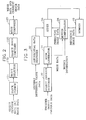
- an object extractor 10 receives digital image data from an external source, and extracts an arbitrary object from a current image represented by the received image data. Then, the object extractor 10 generates object contour data representing contour information of the extracted object.
- the object contour data is supplied to a differential data encoder 20 and a decoding apparatus of Figure 3 to be described later.
- the object contour data contains spatial positions of pixels which determine a contour of the object or spatial positions of segments composed of the pixels.
- the object extractor 10 outputs the object contour data and the received current image data to a mesh generator 12.
- the mesh generator 12 discriminates an object region from the current image based on the object contour data, and performs a signal processing for regular mesh representation with respect to the image in the object region. The detailed structure and operation of the mesh generator 12 will be described with reference to Figure 2.
- a block former 121 in the mesh generator 12 receives the current image data and the object contour data output from the object extractor 10.
- the block former 121 divides the current image represented by the received image data into image blocks each having a predetermined size, and supplies image block data representing image blocks and the object contour data to a block selector 123.
- the block selector 123 selects image blocks containing the image data in the object region among the entire image blocks constituting the current image based on the object contour data.
- the data representing the selected image blocks and the object contour data is output to an object image composer 125.
- image blocks having only image data which do not belong to the object region are not selected. Therefore, the data representing the image blocks which are not selected is not supplied to the object image composer 125.
- the object image composer 125 which receives the data of the selected image blocks merges the selected image blocks and supplies the data representing the object image generated from the merging result and the object contour data to a mesh composer 127.
- the mesh composer 127 receiving the object image data divides the object image into a regular rectangular mesh or a regular triangular mesh.
- the mesh composer 127 divides the object image into grids each having a predetermined size different from a block size.
- a grid has a size smaller than that of a block.
- the mesh composer 127 determines vertices contained in the object region among the vertices of the grids obtained by the division as control points, and determines grids having the control points as regular rectangular meshes.
- the mesh composer 127 outputs rectangular mesh data containing the image data involving the control points of the regular rectangular meshes to a motion estimation and compensation portion 14 of Figure 1.
- the image data involving each control point includes the position of a control point and a gray value at the position of the control point, and the positions of the pixels having positions adjacent to the control point and the gray values.
- the mesh composer 127 also outputs the current image data to a difference value calculator 18.
- the mesh composer 127 divides each regular rectangular mesh obtained through the above process into two regular triangular meshes based on similarity of the image data in the mesh. To judge similarity of the image data of each regular rectangular mesh, the mesh composer 127 compares a difference value between pixel values corresponding to two control points which are located at a diagonal direction of 45° in the regular rectangular mesh, with a difference value between pixel values corresponding to two control points located at a diagonal direction of -45° therein in size. The mesh composer 127 divides the rectangular mesh in the diagonal direction corresponding to the smaller difference value. As a result, two regular triangular meshes are generated every rectangular mesh. The mesh composer 127 outputs the triangular mesh data containing the image data involving the control points of the regular triangular meshes to the motion estimation and compensation portion 14. The mesh composer 127 outputs the current image data to a difference value calculator 18 as well.
- the motion estimation and compensation portion 14 performs a motion estimation and compensation using the reference image data stored in the memory 16 and the mesh data involving the object image in the current image received from the mesh former 12.
- the motion estimation and compensation portion 14 first compares in magnitude the image data involved in the control points of each mesh with the reference image data stored in the memory 16.
- Each control point corresponds to a single pixel ideally. That is, a control point is expressed by a spatial position of a pixel and a gray value. However, it is actually difficult to exactly find out a position having image data similar to the control point in the reference image by only pixel to pixel comparison.
- the image data involving each control point is image data which is involved in a pixel corresponding to the control point and a plurality of pixels neighbouring the pixel corresponding to the control point, as described in the mesh composer 127.
- the motion estimation and compensation portion 14 determines a position in the reference image having the image data which is most similar to the image data of the control point based on the data magnitude comparison result. Then, the motion estimation and compensation portion 14 determines a motion vector representing movement between a control point and a corresponding position in the reference image. If the motion vectors are determined with respect to all the control points, the motion estimation and compensation portion 14 performs spatial transformation such as image warping using the determined motion vectors, and generates a predictive image with respect to the current image.
- the data representing the predictive image is output to the difference value calculator 18 and the adder 24.
- the motion information representing the motion vectors corresponding to all the control points is supplied to the Figure 3 apparatus. Since the above-described spatial transformation is well known in the field of a digital image processing, the detailed description thereof will be omitted.
- the difference value calculator 18 calculates difference values between the current image data received from the mesh generator 12 and the predicitve image data output from the motion estimation and compensation portion 14. The difference value calculation is performed between the pixels having corresponding positions with respect to the current image and the predictive image, and the resultant difference value data is output to a differential data encoder 20.
- the differential data encoder 20 encodes difference value data in the object region determined by the object contour data of the object extractor 10 among the difference value data supplied from the difference value calculator 18. If the data encoded by the differential data encoder 20 is defined as difference value data in the object region, only difference value data involving the object of the current image is encoded. Accordingly, the differential data encoder 20 can perform a more efficient encoding operation with respect to the current image.
- the differential data encoder 20 encodes the object contour data received from the object extractor 10 as well.
- the differential data encoder 20 uses a well-known orthogonal transform coding method including discrete cosine transform (DCT) and so on.
- DCT discrete cosine transform
- the encoded object contour data, the encoded difference value data and the motion information are transmitted to a decoding apparatus of Figure 3 to be described later via a transmission channel (not shown), or are recorded on a storage medium used in the decoding apparatus of Figure 3.
- a differential data decoder 22 receiving the encoded difference value data from the differential data encoder 20 restores the difference value data via a reverse procedure of the signal processing of the differential data encoder 20.
- the adder 24 adds the predicitve image data output from the motion estimation and compensation portion 14 and the difference value data of the differential data decoder 22, and outputs the added result to the memory 16.
- the data output from the adder 24 is data of the current image from which motion estimation and compensation has been performed, and is stored in the memory 16 to be used as reference image data for motion estimation and motion compensation with respect to a next image.
- a motion image decoding apparatus shown in Figure 3 receives the encoded difference value data, the encoded object contour data and the motion information generated by the Figure 1 apparatus.
- An object contour restorer 30 decodes the encoded object contour data.
- the object contour data is output to a mesh generator 34.
- the mesh generator 34 receiving the object contour data divides the entire image into grids each having a predetermined size, determines vertices existing in the object region determined by the object contour data as control points among the vertices of the grids obtained by the division, and determines the grids having the control points as rectangular meshes.
- the mesh generator 12 of Figure 1 is designed to generate mesh data representing the rectangular meshes
- the mesh generator 34 also generates mesh data representing rectangular meshes.
- the mesh generator 34 generates mesh data involving the triangular meshes, the mesh generator 34 supplies the generated mesh data to a motion compenstor 38 and supplies the object contour data to an adder 36.
- a differential data decoder 32 decodes the encoded difference value data generatd by the Figure 1 apparatus.
- the difference value data is output to the adder 36.
- the motion compensator 38 receives the mesh data output from the mesh generator 34 and the motion information generated by the Figure 1 apparatus.
- the motion compensator 38 generates predictive image data using control points contained in the mesh data corresponding to a current image, motion vectors corresponding to all the control points and contained in motion information, and the reference image data stored in the memory 40.
- the motion compensator 38 uses a motion vector corresponding to each control point to find out a position in the reference image which is most similar to the control point, and then uses spatial transformation such as image warping to generate predictive image data for a current image.
- the motion compensator 38 outputs the generated predictive image data to an adder 36.
- the adder 36 receives the predictive image data output from the motion compensator 38 and the difference value data output from the differential data decoder 32.
- the adder 36 adds only predictive image data in the object region determined by the object contour data supplied from the mesh generator 34 among the entire predictive image data to the difference value data corresponding thereto. By doing so, image data with respect to an object in the current image can be restored.
- the output data of the adder 36 is stored in the memory 40 to be used as reference image data for motion compensation of a next image.
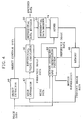
- Figure 4 is a block diagram showing a motion image encoding apparatus according to another preferred embodiment of the present invention. Since the blocks of Figure 4 having the same reference numerals as those of the Figure 1 blocks perform the same functions as those of the corresponding blocks of figure 1, the detailed description thereof will be omitted.
- the Figure 1 apparatus uses the meshes obtained from the current image and the reference image data stored in the memory 16 to generate predictive image data. On the contrary, the Figure. 4 apparatus uses meshes obtained from reference image data stored in a memory 48 and externally input current image data to generate predictive image data.
- the external current image data is input to the object extractor 10 and a motion estimation and compensation portion 44.
- the object extractor 10 generates object contour data using the current image data.
- the object contour data is output to the differential data encoder 20.
- a mesh generator 42 reads the reference image data stored in the memory 48 and divides the entire reference into irregular meshes. For such division, the mesh generator 42 divides the reference image into regular rectangular meshes and divides the regular rectangular meshes into regular triangular meshes again. Since the method for generation of the regular rectangular mesh and the regular triangular mesh is same as a signal processing of the Figure 1 mesh generator 12, the detailed description thereof will be omitted.
- Another function of the mesh generator 42 generates an irregular mesh from regular rectangular meshes or regular triangular meshes.
- the procedure of generating the irregular mesh is as follows.
- the mesh generator 42 removes one selected among the control points of the regular triangular meshes, and performs triangulation with respect to the region from which the control point is removed.
- the triangular meshes generated by the triangulation have irregular triangular shapes.
- Such control point removal and triangulation repeats until the number of the remaining control points is identical to a predetermined value.
- a quantified difference value between image descriptiveness obtained when the control point has been removed from a support region of the control point and that when the former has not been removed.
- the support region is a region surrounded by neighbouring control points to a corresponding control point and lines connecting the neighbouring control points.
- a control point corresponding to the smallest difference value among the quantified difference values of the image descriptiveness does little to contribute for the image descriptiveness, to accordingly be removed.
- the irregular mesh generation technique is disclosed in a paper entitled "Irregular Triangular Mesh Representation Based on Adaptive Control Point Removal” published in SPIE's 1996 symposium on Visual Communications and Image Processing by Kang W. Chun, Byungwoo Jean and Jae M. Jo.
- the mesh generator 42 outputs information about the finally generated irregular triangular meshes, that is, the irregular mesh data representing the remaining control points and the irregular meshes surrounded by the control points, to a motion estimation and compensation portion 44.
- the mesh generator 42 outputs the reference image data read from the memory 48 to a difference value calculator 46 as well.
- the motion estimation and compensation portion 44 receives the externally supplied current image data and the irregular mesh data of the mesh generator 42, and reads the reference image data stored in the memory 48.
- the motion estimation and compensation portion 44 determines corresponding positions in the current image having the image data which is most similar to the control points of the irregular meshes. After the corresponding positions are determined, the motion estimation and compensation portion 44 generates motion vectors between the control points and the corresponding positions and uses spatial transformation to generate a predictive image using the current image.
- the predictive image data is supplied to the difference value calculator 46 and the adder 24, and the motion information representing the motion vectors are transmitted via a transmission channel or recorded on a storage medium to be used for a decoding apparatus.
- the difference value calculator 46 generates difference value data between the reference image data received from the mesh generator 42 and the predictive image data from the motion estimation and compensation portion 44, to supply the difference value data to a differential data encoder 20.
- the differential data encoder 20 encodes the object contour data output from the object extractor 10 and the difference value data output from the difference value calculator 46.
- the differential data encoder 20 processes the input data in the same manner as those of the corresponding blocks of Figure 1.
- the encoded data output from the differential data encoder 20 includes data obtained by encoding the difference value data in the object region and the encoded object contour data.
- the encoded data is transmitted to a receiver via a transmission channel (not shown), or is recorded on a recording medium (not shown).
- the encoded difference value data among the encoded data is transmitted to the differential data decoder 22.
- the differential data decoder 22 decodes the difference value data encoded in the differential data encoder 20, to supply the decoded difference value data to the adder 24.
- the adder 24 adds the predictive image data supplied from the motion estimation and compensation portion 44 and the difference value data of the differential data decoder 22, and the resultant data is stored in the memory 48, to be used as reference image data for motion estimation and motion compensation for a next image.
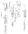
- Figure 5 shows a motion image decoding apparatus corresponding to the Figure 4 apparatus. Since blocks having the same reference numerals as those of the Figure 3 blocks among the blocks shown in Figure 5 have the same functions as those of the Figure 3 blocks, the detailed description thereof will be omitted.
- the encoded object contour data is input to an object contour restorer 30 and the motion information is input to a motion compensator 52. Also, the encoded difference value data is supplied to the differential data decoder 32.
- the differential data decoder 32 decodes the encoded difference value data to output the decoded difference value data to an adder 56.
- the object contour restorer 30 decodes the encoded object contour data to output the decoded object contour data to a mesh generator 51.
- the mesh generator 51 reads the reference image data stored in a memory 54, and divides the object region in the reference image determined by the object contour data via the same signal processing as that of the Figure 4 mesh generator 42, into irregular meshes.
- the mesh data output from the mesh generator 51 is supplied to the motion compensator 52.
- the motion compensator 52 uses the mesh data, the motion information and the reference image data stored in the memory 54 to generate the predictive image data.
- the adder 56 adds the predictive image data and the difference value data output from the differential data decoder 32.
- the resultant current image is stored in the memory 54 to be used as reference image data for motion compensation of a next image.
- the encoding and decoding system performs motion estimation and motion compensation based on mesh representation with respect to an arbitrary object contained in an image. As a result, a more efficient encoding can be performed compared with a case when motion estimation and motion compensation is performed with respect to the entire image. Thus, an apparatus appropriate for applications requiring a very low bit rate can be designed.
Landscapes
- Engineering & Computer Science (AREA)
- Multimedia (AREA)
- Signal Processing (AREA)
- Compression Or Coding Systems Of Tv Signals (AREA)
- Compression, Expansion, Code Conversion, And Decoders (AREA)
Claims (3)
- Bildkodiervorrichtung, die umfasst:eine Informationseingabeeinrichtung zum Empfangen von Konturinformationen eines Objektes und eines Bewegungsvektors,eine Objektkontur-Wiederherstellungseinrichtung (30) zum Wiederherstellen einer Kontur des Objektes unter Verwendung der Konturinformation des Objektes undeine Bewegungskompensationseinrichtung (52) zum Durchführen einer räumlichen Transformation des Objektes in Beziehung zu dem Bewegungsvektor,dadurch gekennzeichnet, dass
der Bewegungsvektor ein Bewegungsvektor eines Knotenpunktes eines Netzes ist,
die Vorrichtung des Weiteren eine Netzerzeugungseinrichtung (51) zum Wiederherstellen einer Netzstruktur für das Objekt unter Verwendung der Konturinformation des Objektes umfasst und
die Bewegungskompensationseinrichtung (52) räumliche Transformation als eine Einheit des Netzes unter Verwendung des Bewegungsvektors auf dem Knotenpunkt des Netzes und der Netzstruktur für das Referenzobjekt durchführt, um ein Prognoseobjekt zu erzeugen. - Verfahren zum Dekodieren von kodierten Daten, um aus diesen ein visuelles Objekt wiederherzustellen, das Verfahren umfasst:Erhalten einer Vielzahl von Bewegungsvektoren aus den kodierten Daten undDurchführen einer räumlichen Transformation unter Verwendung der Vielzahl von Bewegungsvektoren, um das visuelle Objekt wiederherzustellen,dadurch gekennzeichnet, dass
die kodierten Daten von einer Netzdarstellung eines visuellen Objektes erzeugt werden und Netzdaten und Konturinformation umfassen,
die Vielzahl von Bewegungsvektoren eine Relativbewegung zwischen jeweiligen entsprechenden einer Vielzahl von Knotenpunkten der Netzdarstellung des visuellen Objektes und entsprechende räumliche Positionen eines vorgegebenen Referenzobjektes darstellt,
das Verfahren des Weiteren den Schritt des Reproduzierens der Netzdarstellung aus den Netzdaten und der Konturinformation der kodierten Daten umfasst und
der Durchführungsschritt das Durchführen der räumlichen Transformation der reproduzierten Netzdarstellung unter Verwendung der Vielzahl von Bewegungsvektoren umfasst, um das visuelle Objekt wiederherzustellen. - Verfahren nach Anspruch 2, das des Weiteren umfasst:Ersetzen des vorgegebenen Referenzobjektes durch das wiederhergestellte visuelle Objekt.
Priority Applications (2)
| Application Number | Priority Date | Filing Date | Title |
|---|---|---|---|
| EP20060117952 EP1715695A3 (de) | 1996-05-29 | 1997-05-27 | Codierung- und Decodierungssystem für bewegte Bilder mit beliebig geformten Objekten |
| EP20050000322 EP1523196A3 (de) | 1996-05-29 | 1997-05-27 | System zur Codierung Bewegbilder mit beliebigen Objekten enthaltend |
Applications Claiming Priority (2)
| Application Number | Priority Date | Filing Date | Title |
|---|---|---|---|
| KR9618612 | 1996-05-29 | ||
| KR1019960018612A KR100215451B1 (ko) | 1996-05-29 | 1996-05-29 | 임의형태 물체를 포함한 동화상의 부호화 및 복호화시스템 |
Related Child Applications (2)
| Application Number | Title | Priority Date | Filing Date |
|---|---|---|---|
| EP20060117952 Division EP1715695A3 (de) | 1996-05-29 | 1997-05-27 | Codierung- und Decodierungssystem für bewegte Bilder mit beliebig geformten Objekten |
| EP20050000322 Division EP1523196A3 (de) | 1996-05-29 | 1997-05-27 | System zur Codierung Bewegbilder mit beliebigen Objekten enthaltend |
Publications (3)
| Publication Number | Publication Date |
|---|---|
| EP0810792A2 EP0810792A2 (de) | 1997-12-03 |
| EP0810792A3 EP0810792A3 (de) | 2000-12-13 |
| EP0810792B1 true EP0810792B1 (de) | 2006-10-25 |
Family
ID=37402254
Family Applications (3)
| Application Number | Title | Priority Date | Filing Date |
|---|---|---|---|
| EP19970303590 Expired - Lifetime EP0810792B1 (de) | 1996-05-29 | 1997-05-27 | Codierung- und Decodierungssystem für bewegte Bilder mit beliebig geformten Objekten |
| EP20060117952 Withdrawn EP1715695A3 (de) | 1996-05-29 | 1997-05-27 | Codierung- und Decodierungssystem für bewegte Bilder mit beliebig geformten Objekten |
| EP20050000322 Withdrawn EP1523196A3 (de) | 1996-05-29 | 1997-05-27 | System zur Codierung Bewegbilder mit beliebigen Objekten enthaltend |
Family Applications After (2)
| Application Number | Title | Priority Date | Filing Date |
|---|---|---|---|
| EP20060117952 Withdrawn EP1715695A3 (de) | 1996-05-29 | 1997-05-27 | Codierung- und Decodierungssystem für bewegte Bilder mit beliebig geformten Objekten |
| EP20050000322 Withdrawn EP1523196A3 (de) | 1996-05-29 | 1997-05-27 | System zur Codierung Bewegbilder mit beliebigen Objekten enthaltend |
Country Status (7)
| Country | Link |
|---|---|
| US (3) | US6038258A (de) |
| EP (3) | EP0810792B1 (de) |
| JP (1) | JPH1056643A (de) |
| KR (1) | KR100215451B1 (de) |
| CN (2) | CN1146242C (de) |
| DE (1) | DE69736852T2 (de) |
| ES (1) | ES2277350T3 (de) |
Families Citing this family (31)
| Publication number | Priority date | Publication date | Assignee | Title |
|---|---|---|---|---|
| KR100215451B1 (ko) * | 1996-05-29 | 1999-08-16 | 윤종용 | 임의형태 물체를 포함한 동화상의 부호화 및 복호화시스템 |
| KR100535630B1 (ko) * | 1998-06-30 | 2006-06-23 | 주식회사 팬택앤큐리텔 | 디지털 그레이 모양정보/색상정보의 부호화/복호화 방법 |
| KR100620715B1 (ko) * | 1998-06-30 | 2007-04-25 | 주식회사 팬택앤큐리텔 | 디지털 그레이 모양정보/색상정보의 부호화/복호화 방법 |
| WO2000025232A1 (de) * | 1998-10-23 | 2000-05-04 | Siemens Aktiengesellschaft | Verfahren und anordnung zur codierung, decodierung und übertragung eines digitalisierten bildes |
| US6351267B1 (en) | 1998-12-10 | 2002-02-26 | Gizmoz Ltd | Fast transmission of graphic objects |
| JP4126126B2 (ja) * | 1998-12-11 | 2008-07-30 | 株式会社日立製作所 | 送信システム、送信方法 |
| JP3897476B2 (ja) * | 1999-02-15 | 2007-03-22 | キヤノン株式会社 | 画像処理装置及びその方法、コンピュータ可読メモリ |
| KR100611999B1 (ko) * | 1999-08-27 | 2006-08-11 | 삼성전자주식회사 | 그리디 알고리듬을 이용한 객체 기반 콰드 트리 메쉬 움직임 보상방법 |
| FR2802377B1 (fr) * | 1999-12-09 | 2002-03-08 | France Telecom | Procede d'estimation de mouvement entre deux images avec gestion des retournements de mailles et procede de codage correspondant |
| US6909746B2 (en) | 2001-03-30 | 2005-06-21 | Koninklijke Philips Electronics N.V. | Fast robust data compression method and system |
| US20040240543A1 (en) * | 2001-09-04 | 2004-12-02 | Faroudja Yves C. | Low bandwidth video compression |
| CN1838775B (zh) * | 2001-11-30 | 2011-11-23 | 株式会社Ntt都科摩 | 移动图像编码设备及方法、移动图像解码设备及方法 |
| FI114679B (fi) * | 2002-04-29 | 2004-11-30 | Nokia Corp | Satunnaisaloituspisteet videokoodauksessa |
| US7373353B2 (en) | 2002-05-10 | 2008-05-13 | International Business Machines Corporation | Reducing index size for multi-level grid indexes |
| US7143098B2 (en) * | 2002-05-10 | 2006-11-28 | International Business Machines Corporation | Systems, methods, and computer program products to reduce computer processing in grid cell size determination for indexing of multidimensional databases |
| US7383275B2 (en) * | 2002-05-10 | 2008-06-03 | International Business Machines Corporation | Methods to improve indexing of multidimensional databases |
| US7095786B1 (en) | 2003-01-11 | 2006-08-22 | Neo Magic Corp. | Object tracking using adaptive block-size matching along object boundary and frame-skipping when object motion is low |
| JP2005184626A (ja) * | 2003-12-22 | 2005-07-07 | Canon Inc | 画像処理装置 |
| US20050198008A1 (en) * | 2004-03-02 | 2005-09-08 | Adler David W. | Index exploitation for spatial data |
| US7389283B2 (en) * | 2004-12-07 | 2008-06-17 | International Business Machines Corporation | Method for determining an optimal grid index specification for multidimensional data |
| EP2720467B1 (de) | 2005-09-26 | 2017-03-29 | Mitsubishi Electric Corporation | Bewegtbilddecodierungsvorrichtung |
| JP5113077B2 (ja) * | 2005-12-19 | 2013-01-09 | コーニンクレッカ フィリップス エレクトロニクス エヌ ヴィ | 変形可能なメッシュを用いて画像の後処理を容易にする方法 |
| KR20080107965A (ko) * | 2007-06-08 | 2008-12-11 | 삼성전자주식회사 | 객체 경계 기반 파티션을 이용한 영상의 부호화, 복호화방법 및 장치 |
| JP5230372B2 (ja) * | 2008-11-25 | 2013-07-10 | キヤノン株式会社 | 画像処理装置、画像処理方法 |
| JP5661359B2 (ja) * | 2010-07-16 | 2015-01-28 | キヤノン株式会社 | 画像処理装置、画像処理方法、およびプログラム |
| JP5558949B2 (ja) * | 2010-07-16 | 2014-07-23 | キヤノン株式会社 | 画像処理装置、画像処理方法、およびプログラム |
| US9189884B2 (en) * | 2012-11-13 | 2015-11-17 | Google Inc. | Using video to encode assets for swivel/360-degree spinners |
| CN106331722B (zh) * | 2015-07-03 | 2019-04-26 | 华为技术有限公司 | 图像预测方法和相关设备 |
| CN111526360A (zh) | 2016-02-06 | 2020-08-11 | 华为技术有限公司 | 图像编解码方法及装置 |
| KR102724618B1 (ko) | 2024-02-02 | 2024-10-31 | 제이와이스틸 주식회사 | 철재 계단 구조물 및 그 제작 방법 |
| KR102660416B1 (ko) | 2024-02-02 | 2024-04-23 | 박흥순 | 대형 철재 구조물 제작을 위한 철판 연속 가공 방법 및 시스템 |
Family Cites Families (26)
| Publication number | Priority date | Publication date | Assignee | Title |
|---|---|---|---|---|
| JP3037383B2 (ja) * | 1990-09-03 | 2000-04-24 | キヤノン株式会社 | 画像処理システム及びその方法 |
| JP3405788B2 (ja) * | 1993-03-04 | 2003-05-12 | 株式会社東芝 | 動画像符号化装置と動画像復号化装置 |
| EP0625853B1 (de) * | 1993-05-21 | 1999-03-03 | Nippon Telegraph And Telephone Corporation | Bewegtbildkoder und -dekoder |
| JPH08297692A (ja) * | 1994-09-16 | 1996-11-12 | Mitsubishi Electric Corp | 光近接補正装置及び方法並びにパタン形成方法 |
| KR0159575B1 (ko) * | 1994-10-31 | 1999-01-15 | 배순훈 | 영역 분할 부호화 방식의 인접 영역간 불연속 처리 장치 |
| KR100235343B1 (ko) * | 1994-12-29 | 1999-12-15 | 전주범 | 영역분할 기법을 이용한 동영상신호 부호화기의 움직임 벡터 측정장치 |
| EP0721287A1 (de) * | 1995-01-09 | 1996-07-10 | Daewoo Electronics Co., Ltd | Verfahren und Vorrichtung zur Kodierung eines Videosignals |
| US5635929A (en) * | 1995-02-13 | 1997-06-03 | Hughes Aircraft Company | Low bit rate video encoder and decoder |
| JP3086396B2 (ja) * | 1995-03-10 | 2000-09-11 | シャープ株式会社 | 画像符号化装置及び画像復号装置 |
| KR0159370B1 (ko) * | 1995-03-20 | 1999-01-15 | 배순훈 | 물체의 경계를 고려한 영상 부호화방법 및 장치 |
| GB2300287B (en) * | 1995-04-27 | 2000-04-26 | Canon Kk | Method and apparatus for processing finite element meshing model |
| US5654771A (en) * | 1995-05-23 | 1997-08-05 | The University Of Rochester | Video compression system using a dense motion vector field and a triangular patch mesh overlay model |
| JP2701795B2 (ja) * | 1995-06-28 | 1998-01-21 | 日本電気株式会社 | プロセスシミュレーション方法 |
| US5646867A (en) * | 1995-07-24 | 1997-07-08 | Motorola Inc. | Method and system for improved motion compensation |
| JP2798120B2 (ja) * | 1995-08-04 | 1998-09-17 | 日本電気株式会社 | 動き補償フレーム間予測方法及び動き補償フレーム間予測装置 |
| US5691769A (en) * | 1995-09-07 | 1997-11-25 | Daewoo Electronics Co, Ltd. | Apparatus for encoding a contour of an object |
| KR100208375B1 (ko) * | 1995-12-27 | 1999-07-15 | 윤종용 | 동화상 부호화 방법 및 장치 |
| JP2798035B2 (ja) * | 1996-01-17 | 1998-09-17 | 日本電気株式会社 | 適応動きベクトル補間による動き補償フレーム間予測方法 |
| US5736987A (en) * | 1996-03-19 | 1998-04-07 | Microsoft Corporation | Compression of graphic data normals |
| JPH11509709A (ja) * | 1996-05-06 | 1999-08-24 | フィリップス エレクトロニクス ネムローゼ フェンノートシャップ | ビデオ画像を分割符号化及び復号する方法とシステム |
| KR100215451B1 (ko) * | 1996-05-29 | 1999-08-16 | 윤종용 | 임의형태 물체를 포함한 동화상의 부호화 및 복호화시스템 |
| US5936671A (en) * | 1996-07-02 | 1999-08-10 | Sharp Laboratories Of America, Inc. | Object-based video processing using forward-tracking 2-D mesh layers |
| US5907626A (en) * | 1996-08-02 | 1999-05-25 | Eastman Kodak Company | Method for object tracking and mosaicing in an image sequence using a two-dimensional mesh |
| US6047088A (en) * | 1996-12-16 | 2000-04-04 | Sharp Laboratories Of America, Inc. | 2D mesh geometry and motion vector compression |
| US6148026A (en) * | 1997-01-08 | 2000-11-14 | At&T Corp. | Mesh node coding to enable object based functionalities within a motion compensated transform video coder |
| US5818463A (en) * | 1997-02-13 | 1998-10-06 | Rockwell Science Center, Inc. | Data compression for animated three dimensional objects |
-
1996
- 1996-05-29 KR KR1019960018612A patent/KR100215451B1/ko not_active Expired - Fee Related
-
1997
- 1997-05-20 JP JP12993397A patent/JPH1056643A/ja active Pending
- 1997-05-27 EP EP19970303590 patent/EP0810792B1/de not_active Expired - Lifetime
- 1997-05-27 EP EP20060117952 patent/EP1715695A3/de not_active Withdrawn
- 1997-05-27 DE DE1997636852 patent/DE69736852T2/de not_active Expired - Lifetime
- 1997-05-27 EP EP20050000322 patent/EP1523196A3/de not_active Withdrawn
- 1997-05-27 ES ES97303590T patent/ES2277350T3/es not_active Expired - Lifetime
- 1997-05-29 CN CNB991215907A patent/CN1146242C/zh not_active Expired - Fee Related
- 1997-05-29 US US08/864,992 patent/US6038258A/en not_active Expired - Lifetime
- 1997-05-29 CN CNB971129061A patent/CN1134988C/zh not_active Expired - Fee Related
-
2000
- 2000-02-16 US US09/504,934 patent/US6236680B1/en not_active Expired - Lifetime
-
2001
- 2001-04-26 US US09/842,405 patent/US6744817B2/en not_active Expired - Fee Related
Also Published As
| Publication number | Publication date |
|---|---|
| CN1177259A (zh) | 1998-03-25 |
| US6038258A (en) | 2000-03-14 |
| EP1715695A2 (de) | 2006-10-25 |
| CN1254238A (zh) | 2000-05-24 |
| US6236680B1 (en) | 2001-05-22 |
| KR970078652A (ko) | 1997-12-12 |
| EP0810792A2 (de) | 1997-12-03 |
| EP0810792A3 (de) | 2000-12-13 |
| KR100215451B1 (ko) | 1999-08-16 |
| ES2277350T3 (es) | 2007-07-01 |
| CN1146242C (zh) | 2004-04-14 |
| EP1715695A3 (de) | 2008-10-22 |
| CN1134988C (zh) | 2004-01-14 |
| EP1523196A3 (de) | 2006-01-18 |
| EP1523196A2 (de) | 2005-04-13 |
| JPH1056643A (ja) | 1998-02-24 |
| DE69736852D1 (de) | 2006-12-07 |
| DE69736852T2 (de) | 2007-09-06 |
| US20010014119A1 (en) | 2001-08-16 |
| US6744817B2 (en) | 2004-06-01 |
Similar Documents
| Publication | Publication Date | Title |
|---|---|---|
| EP0810792B1 (de) | Codierung- und Decodierungssystem für bewegte Bilder mit beliebig geformten Objekten | |
| US8023754B2 (en) | Image encoding and decoding apparatus, program and method | |
| JP3277111B2 (ja) | 動画像符号化装置および動画像復号化装置 | |
| US8391364B2 (en) | Moving picture encoding device, moving picture decoding device, moving picture encoding method, moving picture decoding method, program, and computer readable recording medium storing program | |
| US5592228A (en) | Video encoder using global motion estimation and polygonal patch motion estimation | |
| KR100480787B1 (ko) | 좌표 인터폴레이터의 키 값 데이터 부호화/복호화 방법 및 장치 | |
| EP0859339A2 (de) | Datenkompression füe bewegende dreidimensionale Objekte | |
| EP1629436B1 (de) | Transformations basiertes restbewegungsrahmen kodierungsverfahren mit übervollständiger basis und zugehörige vorrichtung zur videokompression | |
| EP1239680A2 (de) | Verfahren und Vorrichtung zur Kodierung der Verformunginformation eines 3D Objektes | |
| JPH1093972A (ja) | 輪郭符号化方法 | |
| US20050078753A1 (en) | Inter-frame predicted image synthesizing method | |
| KR19980018127A (ko) | 화상 부호화 방법, 화상 복호화 방법, 그 방법을 이용한 화상 부호화 장치, 화상 복호화 장치 및 그 방법을 기록하는 기록매체 | |
| JPH08317410A (ja) | 映像信号符号化方法及びその装置 | |
| KR20130022541A (ko) | 영상의 부호화 방법 및 장치, 및 영상의 복호화 방법 및 장치 | |
| EP0929976B1 (de) | Verfahren und vorrichtung zur bewegungsschätzung | |
| JP3277116B2 (ja) | 動画像符号化装置および動画像復号化装置 | |
| KR100561836B1 (ko) | 3차원 애니메이션 객체의 형태 변환 정보에 대한 키 값부호화 방법 및 그 장치 | |
| WO2006038679A1 (ja) | 動画像符号化の装置、方法及びプログラムと、動画像復号の装置方法及びプログラム | |
| KR100207391B1 (ko) | 적응적인 벡터 양자화를 이용한 영상 부호화 시스템 및 그의 움직임 정보 검출 방법 | |
| Park et al. | Topological surgery encoding improvements based on adaptive bit allocation and DFSVQ | |
| KR100240344B1 (ko) | 적응적인 윤곽선 부호화 장치 및 방법 | |
| KR100220680B1 (ko) | 물체 윤곽 부호화를 위한 버텍스 부호화 장치 | |
| KR100220581B1 (ko) | 물체 윤곽 부호화를 위한 버텍스 부호화 장치 | |
| JPH06225288A (ja) | 動き補償予測符号化および復号化装置 | |
| Mohsenian et al. | Composite predictive vector quantizer for encoding of still images |
Legal Events
| Date | Code | Title | Description |
|---|---|---|---|
| PUAI | Public reference made under article 153(3) epc to a published international application that has entered the european phase |
Free format text: ORIGINAL CODE: 0009012 |
|
| 17P | Request for examination filed |
Effective date: 19970604 |
|
| AK | Designated contracting states |
Kind code of ref document: A2 Designated state(s): DE ES GB |
|
| PUAL | Search report despatched |
Free format text: ORIGINAL CODE: 0009013 |
|
| AK | Designated contracting states |
Kind code of ref document: A3 Designated state(s): DE ES GB |
|
| 17Q | First examination report despatched |
Effective date: 20010725 |
|
| AKX | Designation fees paid |
Free format text: DE ES GB |
|
| GRAP | Despatch of communication of intention to grant a patent |
Free format text: ORIGINAL CODE: EPIDOSNIGR1 |
|
| GRAS | Grant fee paid |
Free format text: ORIGINAL CODE: EPIDOSNIGR3 |
|
| GRAA | (expected) grant |
Free format text: ORIGINAL CODE: 0009210 |
|
| AK | Designated contracting states |
Kind code of ref document: B1 Designated state(s): DE ES GB |
|
| REG | Reference to a national code |
Ref country code: GB Ref legal event code: FG4D |
|
| REF | Corresponds to: |
Ref document number: 69736852 Country of ref document: DE Date of ref document: 20061207 Kind code of ref document: P |
|
| REG | Reference to a national code |
Ref country code: ES Ref legal event code: FG2A Ref document number: 2277350 Country of ref document: ES Kind code of ref document: T3 |
|
| PLBE | No opposition filed within time limit |
Free format text: ORIGINAL CODE: 0009261 |
|
| STAA | Information on the status of an ep patent application or granted ep patent |
Free format text: STATUS: NO OPPOSITION FILED WITHIN TIME LIMIT |
|
| 26N | No opposition filed |
Effective date: 20070726 |
|
| PGFP | Annual fee paid to national office [announced via postgrant information from national office to epo] |
Ref country code: ES Payment date: 20120427 Year of fee payment: 16 |
|
| PGFP | Annual fee paid to national office [announced via postgrant information from national office to epo] |
Ref country code: DE Payment date: 20130423 Year of fee payment: 17 Ref country code: GB Payment date: 20130426 Year of fee payment: 17 |
|
| REG | Reference to a national code |
Ref country code: DE Ref legal event code: R119 Ref document number: 69736852 Country of ref document: DE |
|
| GBPC | Gb: european patent ceased through non-payment of renewal fee |
Effective date: 20140527 |
|
| REG | Reference to a national code |
Ref country code: DE Ref legal event code: R119 Ref document number: 69736852 Country of ref document: DE Effective date: 20141202 |
|
| PG25 | Lapsed in a contracting state [announced via postgrant information from national office to epo] |
Ref country code: DE Free format text: LAPSE BECAUSE OF NON-PAYMENT OF DUE FEES Effective date: 20141202 |
|
| PG25 | Lapsed in a contracting state [announced via postgrant information from national office to epo] |
Ref country code: GB Free format text: LAPSE BECAUSE OF NON-PAYMENT OF DUE FEES Effective date: 20140527 |
|
| REG | Reference to a national code |
Ref country code: ES Ref legal event code: FD2A Effective date: 20150626 |
|
| PG25 | Lapsed in a contracting state [announced via postgrant information from national office to epo] |
Ref country code: ES Free format text: LAPSE BECAUSE OF NON-PAYMENT OF DUE FEES Effective date: 20140528 |