EP0809883B1 - Dispositif de correction des distorsions dans une section de propagation d'un systeme de transmission - Google Patents
Dispositif de correction des distorsions dans une section de propagation d'un systeme de transmission Download PDFInfo
- Publication number
- EP0809883B1 EP0809883B1 EP96900533A EP96900533A EP0809883B1 EP 0809883 B1 EP0809883 B1 EP 0809883B1 EP 96900533 A EP96900533 A EP 96900533A EP 96900533 A EP96900533 A EP 96900533A EP 0809883 B1 EP0809883 B1 EP 0809883B1
- Authority
- EP
- European Patent Office
- Prior art keywords
- filter
- linear
- coefficients
- transmission system
- accordance
- Prior art date
- Legal status (The legal status is an assumption and is not a legal conclusion. Google has not performed a legal analysis and makes no representation as to the accuracy of the status listed.)
- Expired - Lifetime
Links
- 230000005540 biological transmission Effects 0.000 title claims description 21
- 238000000034 method Methods 0.000 description 10
- 230000003044 adaptive effect Effects 0.000 description 4
- 230000003595 spectral effect Effects 0.000 description 4
- 230000006978 adaptation Effects 0.000 description 2
- 230000002238 attenuated effect Effects 0.000 description 2
- 238000013016 damping Methods 0.000 description 2
- 230000001934 delay Effects 0.000 description 2
- 238000011161 development Methods 0.000 description 2
- 230000018109 developmental process Effects 0.000 description 2
- 238000010586 diagram Methods 0.000 description 2
- 230000000694 effects Effects 0.000 description 1
Images
Classifications
-
- H—ELECTRICITY
- H03—ELECTRONIC CIRCUITRY
- H03H—IMPEDANCE NETWORKS, e.g. RESONANT CIRCUITS; RESONATORS
- H03H21/00—Adaptive networks
- H03H21/0012—Digital adaptive filters
- H03H21/0043—Adaptive algorithms
Definitions
- the invention relates to a device for equalization Error path in a transmission system, especially one electrical-acoustic mixed transmission system like it can be used particularly advantageously in a system for active noise reduction, which in the preamble of claim 1 defined genus.
- US-A-5 243 686 describes a method for parameter determination acoustic signals based on a multi-stage linear Predictor based.
- Information becomes first and second Order determined and combined with each other, for example analyze acoustic signal sources and make a comparison identify with a known pattern. This can e.g. B. to identify different vehicles by analyzing the Engine noise serve.
- the inventive device for equalization Error route in a transmission system with the characteristic Features of claim 1 has the advantage of complete equalization of the error distance without adding additional large delays. For this, a minimal phase system used. Through this equalization of amounts no frequency component of the signal comes attenuated much more at the goal than others.
- the basic idea behind the present invention is in that the equalizer is constructed from a transversal filter and that the design for this transversal filter is based on the Basis of the linear prediction is based.
- the associated autocorrelated ⁇ ( ⁇ ) is determined from a specific number NE of coefficients of the identified route impulse response h Err (k) of the error route according to the following equation:
- the Durbin-Levinson recursion is used to solve the Yule-Walker equations for the coefficients a 1 ... a N of the predeterminable order (N) of the linear predictor.
- the System consists of a transmission block, which in particular in Form of a digital filter is described.
- linear is also particularly advantageous Predictor as an equalization device in one Transmission system, especially in a transmission system, which consists of both electrical and acoustic Components exist.
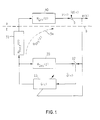
- FIG. 1 shows a structure diagram in control engineering representation with which an application of the linear predictor according to the invention in a system for active noise reduction is explained.
- the equalizer is implemented as a transversal filter.
- the design of this filter is based on the principle of linear prediction.
- the associated autocorrelated ⁇ ( ⁇ ) is determined from a certain number NE, for example 100, of coefficients of an identified route impulse response h err (k). The equation for this is as follows:
- the linear predictor as described above will used or applied to a system.
- This system exists preferably from a transmission block.
- the transmission block in turn it is preferably described by an FIR filter.
- a FIR filter Finite Impulse Response Filter
- a FIR filter is a filter with limited response to an impulse.
- the FIR filter forms an equalization device in one Error path of a transmission system, especially one such, which both from electrical, as well as from acoustic components.
- FIG. 1 the use of the linear predictor according to the invention in an arrangement for active noise reduction, which is constructed in the form of a control or feedback structure, is shown on a structural diagram in a control-technical representation.
- the reference and error sensors coincide, ie the only microphone signal used serves both to control an adaptive controller 10 and to control the adaptation of this controller 10.
- An equalizer is inserted into the system.
- a block 40 is shown on the acoustic side A, which represents a fault path with the transfer function H Err (z).
- a compensation signal y (k) is present at the output of this error path, which is superimposed with a noise d (k).
- the result of this superposition is determined as an error signal e (k).
- This error signal e (k) is on the electrical side E, which is symbolically separated from the acoustic side A by the dashed line D, the point 12 and the adaptation input of the block 10, which the adaptive controller 10 with the function G (z ) represents, fed.
- the output of the controller 10 is routed to the input of a block 31, which represents the equalizer with the equalized transfer function H Entz (z).
- the output of the controller 10 is routed to the input of a block 20, which represents the route model of the entire error route with the transfer function H Ges (z).
- the entire error distance on the electrical side E, ie block 31, and on the acoustic side A, ie block 40, is indicated by the curved arrow 34 shown in broken lines. It can also be called the transfer function H Ges (z).
- a route model 20, which is connected antiparallel to the controller 10, has the same transfer function. The output of the controller 10 is fed to this line model 20 at its input. The output of the route model 20 is given to the summation point 12 with a negative sign.
- a signal d (k) is generated, which can be referred to as a cleaned up noise, in which the "as pure" noise as possible is found and fed to the controller 10 for generating an adequate compensation signal y (k).
- this feedback structure designed in this way an equivalent control or controller feedforward arrangement is made possible by determining the interference noise d (k) as precisely as possible.
- the linear predictor according to the present invention takes place with great effectiveness use in digital systems to get there the distance with linear distortions increases equalize.
- the individual signal components thus appear different frequencies not attenuated to different degrees, but essentially with the original amplitude.
- the signal thus obtained is particularly good in connected adaptive controllers to use because of the low Delays responding to changes as quickly as possible the spectral composition of the variable to be controlled enable.
Landscapes
- Soundproofing, Sound Blocking, And Sound Damping (AREA)
- Filters That Use Time-Delay Elements (AREA)
- Cable Transmission Systems, Equalization Of Radio And Reduction Of Echo (AREA)
- Surface Acoustic Wave Elements And Circuit Networks Thereof (AREA)
Claims (6)
- Dispositif de correction d'un chemin de défaut dans un système de transmission, notamment un système de transmission électroacoustique mixte comme cela s'applique tout particulièrement à un système de réduction active du bruit,
caractérisé en ce que
le correcteur est formé d'un filtre transversal et sa conception repose sur la base de la prévision linéaire. - Dispositif selon la revendication 1,
caractérisé en ce qu'
à partir d'un nombre déterminé NE de coefficients de la réponse impulsionnelle du chemin identifié hErr(k) du chemin de défaut, on détermine l'autocorrélation correspondante ρ(κ) selon l'équation de définition suivante :
- Dispositif selon la revendication 1 ou 2,
caractérisé en ce qu'
à l'aide de la récurrence Durbin-Levinson, on calcule les équations Yule-Walker pour les coefficients a1... aN du prédicteur linéaire d'ordre (N), prédéterminés, les équations étant les suivantes :et pour les coefficients de la réponse impulsionnelle du correcteur, on en déduit finalement la suite {1, -a1, -a2, ..., -aN}.
- Application d'un prédicteur linéaire à la conception d'un filtre transversal, notamment par la réalisation selon l'une des revendications précédentes, avec un système composé d'un bloc de transmission linéaire sélectif en fréquence décrit notamment sous la forme d'un filtre numérique.
- Application d'un prédicteur linéaire selon la revendication 4 comme dispositif de correction dans un système de transmission notamment dans un système de transmission formé à la fois de composants électriques et de composants acoustiques.
- Application d'un prédicteur linéaire selon l'une des revendications 3 ou 4,
caractérisée en ce que
le filtre du bloc de transmission est un filtre FIR (filtre à réponse impulsionnelle finie), c'est-à-dire un filtre à réponse limitée pour une impulsion.
Applications Claiming Priority (3)
| Application Number | Priority Date | Filing Date | Title |
|---|---|---|---|
| DE19505611A DE19505611A1 (de) | 1995-02-18 | 1995-02-18 | Vorrichtung zur Entzerrung einer Fehlerstrecke in einem Übertragungssystem |
| DE19505611 | 1995-02-18 | ||
| PCT/DE1996/000080 WO1996026573A1 (fr) | 1995-02-18 | 1996-01-20 | Dispositif de correction des distorsions dans une section de propagation d'un systeme de transmission |
Publications (2)
| Publication Number | Publication Date |
|---|---|
| EP0809883A1 EP0809883A1 (fr) | 1997-12-03 |
| EP0809883B1 true EP0809883B1 (fr) | 1999-12-29 |
Family
ID=7754396
Family Applications (1)
| Application Number | Title | Priority Date | Filing Date |
|---|---|---|---|
| EP96900533A Expired - Lifetime EP0809883B1 (fr) | 1995-02-18 | 1996-01-20 | Dispositif de correction des distorsions dans une section de propagation d'un systeme de transmission |
Country Status (5)
| Country | Link |
|---|---|
| EP (1) | EP0809883B1 (fr) |
| JP (1) | JPH11500285A (fr) |
| DE (2) | DE19505611A1 (fr) |
| ES (1) | ES2142568T3 (fr) |
| WO (1) | WO1996026573A1 (fr) |
Families Citing this family (3)
| Publication number | Priority date | Publication date | Assignee | Title |
|---|---|---|---|---|
| DE19649595B4 (de) * | 1996-11-29 | 2006-02-02 | Deutsche Telekom Ag | Messverfahren zur Bestimmung der Übertragungsfaktoren von mehreren Mikrofonen und Meßvorrichtung |
| DE19743171A1 (de) * | 1997-09-30 | 1999-04-01 | Daimler Benz Ag | Verfahren zur Entzerrung eines Empfangssignals |
| AU2002221517A1 (en) * | 2001-12-06 | 2003-06-17 | Linkair Communications, Inc. | A limited impulse response digital filter |
Family Cites Families (1)
| Publication number | Priority date | Publication date | Assignee | Title |
|---|---|---|---|---|
| US5243686A (en) * | 1988-12-09 | 1993-09-07 | Oki Electric Industry Co., Ltd. | Multi-stage linear predictive analysis method for feature extraction from acoustic signals |
-
1995
- 1995-02-18 DE DE19505611A patent/DE19505611A1/de not_active Withdrawn
-
1996
- 1996-01-20 ES ES96900533T patent/ES2142568T3/es not_active Expired - Lifetime
- 1996-01-20 EP EP96900533A patent/EP0809883B1/fr not_active Expired - Lifetime
- 1996-01-20 JP JP8525278A patent/JPH11500285A/ja not_active Abandoned
- 1996-01-20 DE DE59604046T patent/DE59604046D1/de not_active Expired - Fee Related
- 1996-01-20 WO PCT/DE1996/000080 patent/WO1996026573A1/fr active IP Right Grant
Also Published As
| Publication number | Publication date |
|---|---|
| JPH11500285A (ja) | 1999-01-06 |
| WO1996026573A1 (fr) | 1996-08-29 |
| DE19505611A1 (de) | 1996-08-22 |
| EP0809883A1 (fr) | 1997-12-03 |
| DE59604046D1 (de) | 2000-02-03 |
| ES2142568T3 (es) | 2000-04-16 |
Similar Documents
| Publication | Publication Date | Title |
|---|---|---|
| DE3856269T2 (de) | Digitales Entzerrungsgerät mit Möglichkeit zur getrennten Modifikation der Phasen- und Amplitudencharakteristik | |
| DE69028273T2 (de) | Entzerrer | |
| EP0948237B1 (fr) | Procédé pour la suppression du bruit dans un signal de microphone | |
| DE69125349T2 (de) | Einstellungsverfahren für Einrichtungen zur Auslöschung Signalzerstreuungen in Nachrichtenübertragungssystemen | |
| DE60312444T2 (de) | Hybrider adaptiver Entzerrer für optische Übertragungssysteme | |
| DE2749132A1 (de) | Rauschfilter-anordnung | |
| DE3405010A1 (de) | Vorrichtung zur erzeugung eines verzoegerungsschaetzwertes fuer eine echoausloescheinrichtung | |
| DE4322033B4 (de) | Vorrichtung für die Nachfilterung von Rauschen bei der Entscheidungs-Rückkopplungs-Entzerrung | |
| DE60311862T2 (de) | Entzerrer zur abtastwertweisen Entscheidungsrückmeldung im Transformationsbereich | |
| EP0809883B1 (fr) | Dispositif de correction des distorsions dans une section de propagation d'un systeme de transmission | |
| DE69520084T2 (de) | Verfahren und Vorrichtung für die Entzerrung von digitalen Signalen im Frequenzbereich | |
| DE69105527T2 (de) | Saw-laufzeitleitungen mit anzapfungen. | |
| DE10101950C1 (de) | Entscheidungsrückgekoppelte Entzerrervorrichtung | |
| DE19824171A1 (de) | Verfahren und Verarbeitungssystem zum iterativen Aktualisieren der Koeffizienten eines adaptiven Filters | |
| EP0268842B1 (fr) | Egaliseur adaptatif en bande passante pour systèmes numériques à faisceaux hertziens | |
| EP0256286B1 (fr) | Dispositif de filtrage | |
| EP1775851B1 (fr) | Circuit, unité et méthode de compensation de la diaphonie | |
| DE69602962T2 (de) | Filteranordnung mit entscheidungsrückkopplung im frequenzbereich | |
| EP0402519B1 (fr) | Méthode et dispositif pour modifier la portée dynamique d'un circuit adaptatif récursif pour le traitement de signaux en temps discret | |
| DE4405817C2 (de) | Automatischer Entzerrer | |
| DE69809367T2 (de) | Verfahren zur Stabilisierung eines fraktionierten Entzerrers in digitalen Signalempfängern | |
| EP0326672A1 (fr) | Méthode et disposition pour la transmission de signaux numériques | |
| EP0258574A2 (fr) | Dispositif de filtrage | |
| DE3418011C2 (fr) | ||
| DE3610383A1 (de) | Adaptiver entscheidungsrueckgekoppelter entzerrer |
Legal Events
| Date | Code | Title | Description |
|---|---|---|---|
| PUAI | Public reference made under article 153(3) epc to a published international application that has entered the european phase |
Free format text: ORIGINAL CODE: 0009012 |
|
| 17P | Request for examination filed |
Effective date: 19970918 |
|
| AK | Designated contracting states |
Kind code of ref document: A1 Designated state(s): CH DE ES FR GB IT LI SE |
|
| RIN1 | Information on inventor provided before grant (corrected) |
Inventor name: HILLER, CHRISTOPH Inventor name: AREVALO, LUIS Inventor name: BENDEL, KARL |
|
| 17Q | First examination report despatched |
Effective date: 19980804 |
|
| GRAG | Despatch of communication of intention to grant |
Free format text: ORIGINAL CODE: EPIDOS AGRA |
|
| GRAG | Despatch of communication of intention to grant |
Free format text: ORIGINAL CODE: EPIDOS AGRA |
|
| GRAH | Despatch of communication of intention to grant a patent |
Free format text: ORIGINAL CODE: EPIDOS IGRA |
|
| GRAH | Despatch of communication of intention to grant a patent |
Free format text: ORIGINAL CODE: EPIDOS IGRA |
|
| GRAA | (expected) grant |
Free format text: ORIGINAL CODE: 0009210 |
|
| AK | Designated contracting states |
Kind code of ref document: B1 Designated state(s): CH DE ES FR GB IT LI SE |
|
| REG | Reference to a national code |
Ref country code: CH Ref legal event code: EP |
|
| REG | Reference to a national code |
Ref country code: CH Ref legal event code: NV Representative=s name: SCINTILLA AG, DIREKTION |
|
| REF | Corresponds to: |
Ref document number: 59604046 Country of ref document: DE Date of ref document: 20000203 |
|
| ET | Fr: translation filed | ||
| ITF | It: translation for a ep patent filed | ||
| GBT | Gb: translation of ep patent filed (gb section 77(6)(a)/1977) |
Effective date: 20000306 |
|
| REG | Reference to a national code |
Ref country code: ES Ref legal event code: FG2A Ref document number: 2142568 Country of ref document: ES Kind code of ref document: T3 |
|
| PLBE | No opposition filed within time limit |
Free format text: ORIGINAL CODE: 0009261 |
|
| STAA | Information on the status of an ep patent application or granted ep patent |
Free format text: STATUS: NO OPPOSITION FILED WITHIN TIME LIMIT |
|
| 26N | No opposition filed | ||
| REG | Reference to a national code |
Ref country code: GB Ref legal event code: IF02 |
|
| PGFP | Annual fee paid to national office [announced via postgrant information from national office to epo] |
Ref country code: GB Payment date: 20030113 Year of fee payment: 8 |
|
| PGFP | Annual fee paid to national office [announced via postgrant information from national office to epo] |
Ref country code: FR Payment date: 20030117 Year of fee payment: 8 |
|
| PGFP | Annual fee paid to national office [announced via postgrant information from national office to epo] |
Ref country code: SE Payment date: 20030123 Year of fee payment: 8 Ref country code: ES Payment date: 20030123 Year of fee payment: 8 |
|
| PGFP | Annual fee paid to national office [announced via postgrant information from national office to epo] |
Ref country code: CH Payment date: 20030124 Year of fee payment: 8 |
|
| PGFP | Annual fee paid to national office [announced via postgrant information from national office to epo] |
Ref country code: DE Payment date: 20030225 Year of fee payment: 8 |
|
| PG25 | Lapsed in a contracting state [announced via postgrant information from national office to epo] |
Ref country code: GB Free format text: LAPSE BECAUSE OF NON-PAYMENT OF DUE FEES Effective date: 20040120 |
|
| PG25 | Lapsed in a contracting state [announced via postgrant information from national office to epo] |
Ref country code: SE Free format text: LAPSE BECAUSE OF NON-PAYMENT OF DUE FEES Effective date: 20040121 Ref country code: ES Free format text: LAPSE BECAUSE OF NON-PAYMENT OF DUE FEES Effective date: 20040121 |
|
| PG25 | Lapsed in a contracting state [announced via postgrant information from national office to epo] |
Ref country code: LI Free format text: LAPSE BECAUSE OF NON-PAYMENT OF DUE FEES Effective date: 20040131 Ref country code: CH Free format text: LAPSE BECAUSE OF NON-PAYMENT OF DUE FEES Effective date: 20040131 |
|
| PG25 | Lapsed in a contracting state [announced via postgrant information from national office to epo] |
Ref country code: DE Free format text: LAPSE BECAUSE OF NON-PAYMENT OF DUE FEES Effective date: 20040803 |
|
| EUG | Se: european patent has lapsed | ||
| GBPC | Gb: european patent ceased through non-payment of renewal fee |
Effective date: 20040120 |
|
| REG | Reference to a national code |
Ref country code: CH Ref legal event code: PL |
|
| PG25 | Lapsed in a contracting state [announced via postgrant information from national office to epo] |
Ref country code: FR Free format text: LAPSE BECAUSE OF NON-PAYMENT OF DUE FEES Effective date: 20040930 |
|
| REG | Reference to a national code |
Ref country code: FR Ref legal event code: ST |
|
| PG25 | Lapsed in a contracting state [announced via postgrant information from national office to epo] |
Ref country code: IT Free format text: LAPSE BECAUSE OF NON-PAYMENT OF DUE FEES;WARNING: LAPSES OF ITALIAN PATENTS WITH EFFECTIVE DATE BEFORE 2007 MAY HAVE OCCURRED AT ANY TIME BEFORE 2007. THE CORRECT EFFECTIVE DATE MAY BE DIFFERENT FROM THE ONE RECORDED. Effective date: 20050120 |
|
| REG | Reference to a national code |
Ref country code: ES Ref legal event code: FD2A Effective date: 20040121 |