EP0809466B1 - Chirurgisches instrument - Google Patents
Chirurgisches instrument Download PDFInfo
- Publication number
- EP0809466B1 EP0809466B1 EP96906402A EP96906402A EP0809466B1 EP 0809466 B1 EP0809466 B1 EP 0809466B1 EP 96906402 A EP96906402 A EP 96906402A EP 96906402 A EP96906402 A EP 96906402A EP 0809466 B1 EP0809466 B1 EP 0809466B1
- Authority
- EP
- European Patent Office
- Prior art keywords
- instrument
- window
- tube
- shield
- support member
- Prior art date
- Legal status (The legal status is an assumption and is not a legal conclusion. Google has not performed a legal analysis and makes no representation as to the accuracy of the status listed.)
- Expired - Lifetime
Links
- 238000005520 cutting process Methods 0.000 claims description 41
- 239000000463 material Substances 0.000 claims description 15
- 238000011065 in-situ storage Methods 0.000 claims description 5
- 230000004044 response Effects 0.000 claims description 3
- 210000001519 tissue Anatomy 0.000 description 19
- 210000004283 incisor Anatomy 0.000 description 11
- 239000012530 fluid Substances 0.000 description 8
- 229910001220 stainless steel Inorganic materials 0.000 description 6
- 239000010935 stainless steel Substances 0.000 description 6
- 230000008878 coupling Effects 0.000 description 5
- 238000010168 coupling process Methods 0.000 description 5
- 238000005859 coupling reaction Methods 0.000 description 5
- 230000007246 mechanism Effects 0.000 description 4
- 239000002184 metal Substances 0.000 description 4
- 238000000034 method Methods 0.000 description 4
- 230000008859 change Effects 0.000 description 3
- 239000012634 fragment Substances 0.000 description 3
- 206010052428 Wound Diseases 0.000 description 2
- 210000000988 bone and bone Anatomy 0.000 description 2
- 238000005219 brazing Methods 0.000 description 2
- 230000003155 kinesthetic effect Effects 0.000 description 2
- 230000013011 mating Effects 0.000 description 2
- 239000004033 plastic Substances 0.000 description 2
- 239000007787 solid Substances 0.000 description 2
- 238000001356 surgical procedure Methods 0.000 description 2
- 210000005222 synovial tissue Anatomy 0.000 description 2
- 238000003466 welding Methods 0.000 description 2
- 241001474374 Blennius Species 0.000 description 1
- 230000009471 action Effects 0.000 description 1
- 230000003213 activating effect Effects 0.000 description 1
- 238000005452 bending Methods 0.000 description 1
- 230000005540 biological transmission Effects 0.000 description 1
- 238000001574 biopsy Methods 0.000 description 1
- 239000000919 ceramic Substances 0.000 description 1
- 238000010276 construction Methods 0.000 description 1
- 230000003247 decreasing effect Effects 0.000 description 1
- 239000013536 elastomeric material Substances 0.000 description 1
- 239000000835 fiber Substances 0.000 description 1
- 230000002262 irrigation Effects 0.000 description 1
- 238000003973 irrigation Methods 0.000 description 1
- 210000005067 joint tissue Anatomy 0.000 description 1
- 210000003127 knee Anatomy 0.000 description 1
- 210000000629 knee joint Anatomy 0.000 description 1
- 238000004519 manufacturing process Methods 0.000 description 1
- 238000000465 moulding Methods 0.000 description 1
- 230000003287 optical effect Effects 0.000 description 1
- 230000003534 oscillatory effect Effects 0.000 description 1
- 210000004417 patella Anatomy 0.000 description 1
- 229920000642 polymer Polymers 0.000 description 1
- 229920001296 polysiloxane Polymers 0.000 description 1
- 230000000007 visual effect Effects 0.000 description 1
- XLYOFNOQVPJJNP-UHFFFAOYSA-N water Substances O XLYOFNOQVPJJNP-UHFFFAOYSA-N 0.000 description 1
Images


Classifications
-
- A—HUMAN NECESSITIES
- A61—MEDICAL OR VETERINARY SCIENCE; HYGIENE
- A61B—DIAGNOSIS; SURGERY; IDENTIFICATION
- A61B17/00—Surgical instruments, devices or methods
- A61B17/32—Surgical cutting instruments
- A61B17/320016—Endoscopic cutting instruments, e.g. arthroscopes, resectoscopes
- A61B17/32002—Endoscopic cutting instruments, e.g. arthroscopes, resectoscopes with continuously rotating, oscillating or reciprocating cutting instruments
-
- A—HUMAN NECESSITIES
- A61—MEDICAL OR VETERINARY SCIENCE; HYGIENE
- A61B—DIAGNOSIS; SURGERY; IDENTIFICATION
- A61B17/00—Surgical instruments, devices or methods
- A61B17/00234—Surgical instruments, devices or methods for minimally invasive surgery
- A61B2017/00292—Surgical instruments, devices or methods for minimally invasive surgery mounted on or guided by flexible, e.g. catheter-like, means
- A61B2017/003—Steerable
- A61B2017/00318—Steering mechanisms
- A61B2017/00331—Steering mechanisms with preformed bends
-
- A—HUMAN NECESSITIES
- A61—MEDICAL OR VETERINARY SCIENCE; HYGIENE
- A61B—DIAGNOSIS; SURGERY; IDENTIFICATION
- A61B17/00—Surgical instruments, devices or methods
- A61B17/32—Surgical cutting instruments
- A61B17/3209—Incision instruments
- A61B17/3211—Surgical scalpels, knives; Accessories therefor
- A61B2017/32113—Surgical scalpels, knives; Accessories therefor with extendable or retractable guard or blade
Definitions
- This invention relates to surgical instruments, and in particular to powered arthroscopic surgical instruments.
- Powered arthroscopic surgical instruments typically include a rigid, stationary outer tube within which a rigid inner tube is rotated by a motor.
- a cutting implement such as a blade or abrading burr, is disposed on the distal end of the inner tube. Tissue or bone is exposed to the cutting implement through an opening in the distal end of the outer tube, and tissue or bone fragments cut by the rotating blade or burr are drawn through the interior of the inner tube along with irrigating fluid by the use of suction applied at the proximal end of the instrument.
- Examples of such surgical instruments are described in U.S. Patent Nos. 4,203,444, 4,274,414, 4,834,729, and 4.842,578, all of which are assigned to the present assignee.
- the cutting implement disposed at the distal end of instruments of the prior art have tended to lack versatility in their control with the excision of tissue being "all or nothing" event. In certain circumstances, the cutting of tissue may necessitate careful and delicate use of the cutting implement. In other circumstances, a more aggressive approach may be needed. Instruments of the prior art tend to lack this versatility and thus the success of an operation may lie more in the skill of the surgeon to control the cutting implement than might otherwise be desired.
- a surgical instrument comprising:
- the invention allows the user to partially or completely cover the opening by moving the shield, thereby preventing at least some tissue from entering into the instrument through the opening and being cut by the surgical tool.
- the cutting action of the surgical tool can be reduced or disabled by appropriate positioning of the shield.
- the invention allows the user to partially or completely cover one of the openings by moving the shield, thereby preventing at least some tissue from entering into the instrument through that opening and being cut by the surgical tool.
- the user can select between windows that have, for example, different cutting configurations and different rotational orientations.
- one window can be configured for more aggressive cutting than the other.
- the preferred degree of cutting can thus be chosen by moving the shield to cover the opening of the window having the undesired cutting characteristics.
- the windows may be located at different rotational orientations around the distal region of the support member. Thus, even if their cutting characteristics are identical, the windows can be selectively covered and uncovered to change the direction of cutting of the instrument.
- an actuating member e.g., a tube coaxially disposed outside the support member
- the proximal end of the actuating member is rigidly secured to a knob rotatably mounted to a stationary portion of the base.
- the knob may be selectively rotated to a plurality of discrete positions with respect to the base, allowing the shield to be positioned to a corresponding plurality of discrete rotational orientations. Because the actuating member is rotatably coupled to the base, the openings may be selectively covered and uncovered while the instrument remains in situ within the patient.
- a drive member (e.g., a tube disposed coaxially within the support member) extends distally from the base, and transmits a rotational force applied at a proximal end to move at least a portion of the surgical tool, a cutting implement attached to a distal end of the drive member. As the drive member rotates, the edges of the cutting implement move toward and closely past the edges of the windows.
- a hollow passage in the tubular drive member is adapted to receive suction at its proximal end, transporting body material cut by the cutting implement away from a surgical site while the instrument remains in situ for further cutting.
- the support member (e.g., a tube) couples to the base in a manner that allows it to slide axially with respect to the base.
- the support tube is inserted into the actuator tube, and the actuator tube is attached to the base.
- the drive tube is then inserted into the support tube, the outer surface of the distal tip of the drive tube bears against the inner surface of the distal tip of the support tube.
- the support tube can slide axially with respect to the base, this forces the support tube distally until the outer surface of the distal tip of the support tube bears against the inner surface of the distal tip of the actuator tube.
- the support tube is bent, and an actuating member extending distally from the base is relatively flexible at least in the bend region, allowing the actuating member to transmit force through the bend region to move the shield.
- the actuating member e.g., a tube disposed outside the support member
- the drive tube may both be relieved with a series of axially spaced slots in the region of the bend. This arrangement provides the actuating and drive tubes with the requisite transverse flexibility to accommodate the bend, and the necessary torsional stiffness to rotate the shield and the cutting implement, respectively. Because it is bent, the instrument may be used to operate on surgical areas that would otherwise be difficult to reach with a straight-shafted instrument.
- FIG. 9 is an end view of the distal region of the intermediate tube of the surgical instrument, taken along line 9-9 of Fig. 7.
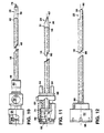
- Figs. 10, 11, and 12 show inner, intermediate, and outer tubes, respectively, of the surgical instrument.
- Fig. 13 is a sectional view of a ratchet mechanism of the surgical instrument, taken along line 13-13 of Fig. 1.
- Fig. 14 shows the surgical instrument in use.
- Fig. 15 shows another embodiment of a surgical instrument.
- Fig. 16 shows another embodiment of a surgical instrument.
- a surgical instrument 10 suitable for performing, e.g., closed, arthroscopic surgery on the knee with a surgical tool 12 includes an intermediate tube 14 within which a rotating inner tube 16 is coaxially disposed.
- intermediate tube 14 is coaxially disposed within a rotatable outer tube 18.
- Tubes 14, 16, and 18 extend distally from a base 20.
- a distal region of outer tube 18 is partially cut away to form an aperture 22, which extends to the longitudinal axis 24 of instrument 10.
- the remaining, solid portion of the distal region of outer tube 18 comprises a shield 26.
- shield 26 alternately covers and uncovers an incisor window 28 and a synovator window 30 located on opposite sides of a window assembly 31 carried at the distal end of intermediate tube 14.
- a window 35 formed by the sharpened, smooth edges 37 of a cutting implement 36 carried at the distal end of inner tube 16 is periodically exposed through incisor window 28 and synovator window 30 as inner tube 16 rotates.
- tissue entering through either incisor window 28 or synovator window 30 can extend into the interior of inner tube 16.
- edges 37 of cutting implement 36 move toward and closely past edges 32, 34 of windows 28, 30 in window assembly 31, severing the tissue projecting therethrough. Together, cutting implement 36 and window assembly 31 comprise surgical tool 12.
- Fig. 11 shows intermediate tube 14, which is also made from a rigid material such as stainless steel or other metal.
- Distal end 56 of intermediate tube 14 supports window assembly 31 (made from, for example, stainless steel and attached to tube 14 by welding or brazing).
- the inner and outer diameters of window assembly 31 are substantially equal to the inner and outer diameters of tube 14.
- Intermediate tube 14 is hollow along its entire length to provide a passage 60 that receives inner tube 16 and cutting implement 36, which extends to the partially closed distal end 62 of window assembly 31.
- the openings defined by windows 28, 30 in window assembly 31 are extensions of passage 60.
- the inner diameter of intermediate tube 14 is only slightly larger than the outer diameter of inner tube 16 (e.g., by approximately 0.002 inches, or 0.051 mm). This allows inner tube 16 to rotate freely but helps minimize wobbling of tube 16 to keep sharp cutting edges 37 of cutting implement 36 and edges 32, 34 of windows 28, 30 closely aligned.
- the proximal end 63 of intermediate tube 16 is rigidly mounted to a coupling 64 located within a cavity 66 of a hub 68 of base 20, shown also in Fig. 2.
- Cavity 66 includes an axially extending keyway 70 sized and located to receive a key 74 on coupling 64.
- Cavity 66 in hub 68 communicates with passage 60, and is configured to receive drive shaft 50.
- inner tube 16 is inserted through hub 68 into passage 60 of intermediate tube 14.
- distal tip 78 of cutting implement 36 Fig. 10
- coupling 64 and intermediate tube 14 are forced distally, until the outer surface of distal tip 62 contacts the inner surface of the partially closed distal tip 80 of outer tube 18.
- intermediate tube 14 can slide axially with respect to hub 68, the gap between the distal tips of intermediate tube 14 and outer tube 18, as well as the gap between the distal tips of inner tube 16 and intermediate tube 14, are essentially zero.
- Outer tube 18, shown in Fig. 12, is also made from a rigid material such as stainless steel or other metal.
- Aperture 22 is defined by smooth, unsharpened edges 84 of tube 18. Edges 84 extend, parallel to axis 24, from a point proximal of distal tip 80 to distal tip 80.
- Aperture 22 is an extension of a central passage 88 in outer tube 18 that runs the entire length of tube 18.
- Proximal region 90 of outer tube 18 is rigidly mounted to a knob 92 that rotatably couples to hub 68 of base 20.
- a pair of fingers 94 extends distally from base 68, parallel to axis 24, and a raised shoulder region 96 encircles base 68 immediately proximal of the point where fingers 94 attach to base 68.
- a mating shoulder 98 on the inner surface of the proximal end of knob 92 engages shoulder 96, as shown in Fig. 2, preventing knob 92 and base 68 from separating longitudinally.
- fingers 94 are quasi-pentagonal in cross-section. With knob 92 installed, the radial outermost point 100 of each finger 94 rests in an a mating apex 102 on the inner surface of knob 92. Apexes 102 are formed by the intersection of adjacent arcuate surfaces 104 of a wall 106 of knob 92. Fingers 94 and arcuate surfaces 104 coact to allow the relative rotational orientation between knob 92 and hub 68 to be changed, in a ratchet-like fashion, in discrete, 180° steps.
- outer tube 18, knob 92, and fingers 94 are oriented so that incisor window 28 is fully covered by shield 26 when knob 92 is rotated to one step, and synovator window 30 is fully covered by shield 26 when knob 92 is rotated to the other step.
- a pair of diametrically opposed bulges 108 on the outer surface of knob 92 are oriented adjacent to, and at the same circumferential location as, apexes 102. Bulges 108 thus make knob 92 easier to grasp, and further indicate to the surgeon when knob 92 has been rotated a sufficient degree. Together, fingers 94 and knob 92 comprise a ratchet assembly.
- surgical instrument 10 is inserted into the distal end of a handpiece 110.
- Outer tube 18 is then introduced as shown through a puncture wound 120 into the knee joint 122, below the patella.
- Light is projected into the joint via a second puncture 124 using a fiber optic light source 126, and a visual image of the surgical site is returned through a separate optical path to a television camera 128.
- the image is delivered by camera 128 onto a television screen 130 for viewing by the surgeon. (Alternatively, the surgeon can view the image using an eyepiece, or the image can be recorded.)
- instrument 10 Different types of surgical instruments such as instrument 10 have rotational and torsional limits. To prevent the surgeon from inadvertently operating instrument 10 at dangerously high speeds and torques, instrument 10 identifies to sensors (not shown) in handpiece 110 what type of instrument it is, and the speed of and torsion applied by motor 112 is controlled so that these limits are not exceeded. (This control technique is described in the aforementioned U.S. Patent No. 4,705,038.)
- tissue 136 which is, e.g., synovial tissue
- the surgeon progressively cuts away synovial tissue 136 by moving surgical instrument 10 from side to side and in the axial direction using handpiece 110 (while viewing television screen 130). For instance, if incisor window 28 is exposed to the joint tissue (that is, if synovator window 30 is fully covered by shield 26), instrument 10 will cut tissue aggressively, because of the configuration of serrated edges 32. If during the procedure the surgeon desires instead to cut tissue less aggressively, the present invention allows him to do so simply by holding knob 92 fixed, and rotating handpiece 110 (and thus hub 68) until incisor window 28 is fully covered by shield 26. This exposes the less-aggressive, smooth-edged synovator window 30.
- the ratchet mechanism provides the surgeon with kinesthetic feedback, indicating when the handpiece 110 has been rotated the requisite 180°. (Alternatively, handpiece 110 can be held fixed and knob 92 rotated. Because incisor window 28 is located on the opposite side of window assembly 31 from synovator window 30, in order to resume cutting the same tissue as before, the surgeon would then rotate instrument 10 180° about axis 24.)
- inner tube 16 can be dnven by motor 112 or may be stationary while the surgeon rotates shield 26.
- the surgeon can resume more aggressive tissue-cutting at any time simply by rotating knob 92 or handpiece 110 In either direction.
- Tissue fragments and other body material cut by surgical tool 12 are withdrawn from the surgical site along with irrigation fluid via central passage 46 of inner tube 16 (Figs. 2. 10) in response to suction applied by vacuum source 114.
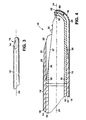
- a surgical instrument 210 embodying the teachings disclosed herein could instead include a bend region 212, as shown in Fig. 15. Bend region 212. which is disposed slightly proximal of the distal end 214 of outer tube 216, angularly offsets surgical tool 218 from a generally straight axis 220 of surgical instrument 210. Bend region 212 enables surgical instrument 210 to operate on surgical areas that are difficult to reach with a straight-shafted Instrument
- a region of an otherwise rigid tube or tubes may be relieved with a series of axially spaced, circumferentially extending slots 228 (only slots 228 in outer tube 216 shown in Fig. 15). Slotting a rotatable tube for flexibility and torque transmission is described in U.S. Patent No. 5,152,744, assigned to the present assignee.
- the slots can be covered with a pliable material such as silicone RTV or a heat-shrinkable polymeric sheath (not shown).
- Intermediate tube 226 is comprised of a material (e.g., stainless steel or other metal, ceramic, or plastic) sufficiently rigid to retain the shape and orientation of bend region 212 during normal surgical use of instrument 210.
- bend region 212 is often preformed during manufacture (e.g., by molding intermediate tube 226 to the desired shape or by bending it around a mandrel)
- bend region 212 can alternatively or additionally be preshaped or reshaped by the surgeon prior to or during the procedure to best match the contours and characteristics of the surgical site.
- FIG. 16 Another embodiment of the present invention, surgical instrument 310, is shown in Fig. 16.
- a bend region 312 in surgical instrument 310 is provided by a curved intermediate tube 314, and an inner tube 316 and an outer tube 318 of the instrument are flexible at least in bend region 312.
- outer tube 318 could be curved, and intermediate tube 314 could be flexible at least in bend region 312.
- a window assembly 320 carried at the distal end of intermediate tube 314 has oppositely disposed incisor and synovator windows 322. 324, within which a cutting Implement (not shown) disposed at the distal end of Innertube 316 rotates.
- a shield 326 carried at the distal end of outer tube 318 can be rotated to selectively cover either of windows 322, 324.
- intermediate tube 314 of surgical instrument 310 is resilient, and a straight, rigid sheath 328 is disposed coaxially outside outer tube 318.
- Sheath 328 is axially slidable with respect to outer tube 318. and in its rest position (shown in Fig 16) the distal end of sheath 328 terminates at a point just proximal of bend region 312. Sliding sheath 328 distally (i.e, in the direction indicated by arrow 330) over bend region 312 causes intermediate tube 314 to straighten out, decreasing the angle of offset provided by bend region 312.
- Sliding sheath 328 proximally back to its rest position allows bend region 312 to recover its preformed curvature.
- the angle of offset of the distal region 332 of instrument 310 with respect to the proximal region 334 of the instrument can be selectively changed while the instrument remains in situ within the patient.
- the shield need not be attached to a member that extends from the base. Rather, the shield may be a cap mounted on the distal end of the intermediate tube. In such a construction, the instrument would have to be withdrawn from the joint space in order to select a different window for cutting. Also, the shield need not rotate, but could be configured instead to slide along the intermediate tube to selectively cover and uncover either or both of the windows. The inner member could likewise translate axially to operate the distal tip surgical tool.
Landscapes
- Health & Medical Sciences (AREA)
- Surgery (AREA)
- Life Sciences & Earth Sciences (AREA)
- Medical Informatics (AREA)
- Nuclear Medicine, Radiotherapy & Molecular Imaging (AREA)
- Engineering & Computer Science (AREA)
- Biomedical Technology (AREA)
- Heart & Thoracic Surgery (AREA)
- Orthopedic Medicine & Surgery (AREA)
- Molecular Biology (AREA)
- Animal Behavior & Ethology (AREA)
- General Health & Medical Sciences (AREA)
- Public Health (AREA)
- Veterinary Medicine (AREA)
- Surgical Instruments (AREA)
- Agricultural Chemicals And Associated Chemicals (AREA)
Claims (25)
- Ein chirurgisches Instrument (10, 210, 310), das Folgendes beinhaltet:eine Basis (20);ein Stützelement (14), das sich distal von der Basis erstreckt und in einem distalen Bereich ein Fenster (28) trägt, welches eine Öffnung definiert;ein chirurgisches Werkzeug (12), das zumindest teilweise in dem distalen Bereich angeordnet und beweglich ist, um sich durch die Öffnung erstreckendes Gewebe zu schneiden;dadurch gekennzeichnet, dass das Stützelement mit einem Schutzschild (26, 222) versehen ist, der zumindest teilweise in dem distalen Bereich angeordnet und mit Bezug auf das Fenster beweglich ist, um die Öffnung zumindest teilweise abzudecken.
- Instrument gemäß Anspruch 1, das ferner ein zweites Fenster beinhaltet, welches eine zweite Öffnung definiert, die in dem distalen Bereich des Stützelements getragen wird.
- Instrument gemäß Anspruch 2, wobei der Schutzschild beweglich ist, um selektiv entweder die Öffnung oder die zweite Öffnung abzudecken.
- Instrument gemäß Anspruch 1, das ferner ein Betätigungselement beinhaltet, welches sich distal von der Basis erstreckt, um eine an einem proximalen Ende des Betätigungselements angewendete Kraft zum Bewegen des Schutzschildes zu übertragen.
- Instrument gemäß Anspruch 4, wobei der Schutzschild an einem distalen Ende des Betätigungselements angebracht ist.
- Instrument gemäß Anspruch 4, wobei das Betätigungselement ein Rohr beinhaltet.
- Instrument gemäß Anspruch 4, wobei das proximale Ende des Betätigungselements unnachgiebig an einem Knopf (92) gesichert ist, der drehbar an einem stationären Abschnitt der Basis montiert ist.
- Instrument gemäß Anspruch 7, wobei der Knopf an dem stationären Abschnitt so montiert ist, dass der Knopf mit Bezug auf den stationären Abschnitt selektiv in eine Vielzahl von diskreten Positionen gedreht werden kann, um dadurch zu ermöglichen, dass der Schutzschild selektiv in eine entsprechende Vielzahl diskreter Drehausrichtungen positioniert werden kann.
- Instrument gemäß Anspruch 1, wobei das Stützelement mit Bezug auf die Basis axial verschiebbar ist.
- Instrument gemäß Anspruch 1, wobei das Stützelement ein Rohr beinhaltet.
- Instrument gemäß Anspruch 1, wobei das Fenster in einem Zusammenbau, der an einem distalen Ende des Stützelements angebracht ist, definiert ist.
- Instrument gemäß Anspruch 1, das ferner ein Antriebselement beinhaltet, welches sich distal von der Basis erstreckt, um eine an einem proximalen Ende des Antriebselements angewendete Kraft zum Bewegen zumindest eines Abschnitts des chirurgischen Werkzeugs zu übertragen.
- Instrument gemäß Anspruch 12, wobei das chirurgische Werkzeug ein Schneidegerät beinhaltet, das an einem distalen Ende des Antriebselements angebracht ist.
- Instrument gemäß Anspruch 13, wobei sich Kanten des Schneidegeräts als Reaktion auf die von dem Antriebselement übertragene Kraft in Richtung auf Kanten des Fensters und dicht an ihnen vorbei bewegen.
- Instrument gemäß Anspruch 14, wobei sich das Schneidegerät als Reaktion auf eine von dem Antriebselement übertragene Drehkraft mit Bezug auf das Fenster dreht.
- Instrument gemäß Anspruch 12, wobei das Antriebselement ein Rohr beinhaltet.
- Instrument gemäß Anspruch 15, wobei das Antriebselement hohl ist und ausgeführt ist, um an seinem proximalen Ende Sog zu empfangen und um Körpermaterial, das von dem Schneidegerät geschnitten worden ist, von einer Chirurgiestelle weg zu transportieren, während das Instrument zum weiteren Schneiden in situ verbleibt.
- Instrument gemäß Anspruch 1, das ferner einen Biegungsbereich (212, 312) in dem Stützelement beinhaltet.
- Instrument gemäß Anspruch 18, das ferner ein Betätigungselement beinhaltet, welches sich distal von der Basis erstreckt, um eine an einem proximalen Ende des Betätigungselements angewendete Kraft zum Bewegen des Schutzschildes durch den Biegungsbereich zu übertragen, wobei das Betätigungselement zumindest in dem Biegungsbereich relativ flexibel ist.
- Instrument gemäß Anspruch 19, wobei das Betätigungselement ein Rohr ist, das außerhalb des Stützelements angeordnet ist, und wobei das Rohr mit einer Reihe axial mit Abstand angeordneter Schlitze in der Gegend des Biegungsbereichs ausgespart ist, um das Rohr relativ flexibel zu machen.
- Instrument gemäß Anspruch 18, wobei das Stützelement zumindest in dem Biegungsbereich relativ verformbar ist.
- Instrument gemäß Anspruch 21, das ferner eine unnachgiebige Scheide beinhaltet, die mit Bezug auf das Stützelement koaxial angeordnet und axial verschiebbar ist.
- Chirurgisches Instrument gemäß Anspruch 1, das ferner Folgendes beinhaltet:Stützelement, das in dem distalen Bereich ein erstes Fenster und ein zweites Fenster trägt, die eine jeweilige erste und zweite Öffnung definieren; undder Schutzschild mit Bezug auf die Fenster beweglich ist, um selektiv eine der Öffnungen abzudecken.
- Instrument gemäß Anspruch 23, wobei der Schutzschild beweglich ist, um zumindest teilweise eine der Öffnungen abzudecken.
- Instrument gemäß Anspruch 23, wobei das erste Fenster für aggressiveres Schneiden konfiguriert ist als das zweite Fenster.
Applications Claiming Priority (3)
| Application Number | Priority Date | Filing Date | Title |
|---|---|---|---|
| US388992 | 1995-02-15 | ||
| US08/388,992 US5601583A (en) | 1995-02-15 | 1995-02-15 | Surgical instrument |
| PCT/US1996/001920 WO1996025103A1 (en) | 1995-02-15 | 1996-02-15 | Surgical instrument |
Publications (3)
| Publication Number | Publication Date |
|---|---|
| EP0809466A1 EP0809466A1 (de) | 1997-12-03 |
| EP0809466A4 EP0809466A4 (de) | 2001-11-21 |
| EP0809466B1 true EP0809466B1 (de) | 2006-11-22 |
Family
ID=23536402
Family Applications (1)
| Application Number | Title | Priority Date | Filing Date |
|---|---|---|---|
| EP96906402A Expired - Lifetime EP0809466B1 (de) | 1995-02-15 | 1996-02-15 | Chirurgisches instrument |
Country Status (8)
| Country | Link |
|---|---|
| US (1) | US5601583A (de) |
| EP (1) | EP0809466B1 (de) |
| JP (1) | JP3767903B2 (de) |
| AT (1) | ATE345737T1 (de) |
| AU (1) | AU690435B2 (de) |
| CA (1) | CA2210523A1 (de) |
| DE (1) | DE69636717T2 (de) |
| WO (1) | WO1996025103A1 (de) |
Cited By (2)
| Publication number | Priority date | Publication date | Assignee | Title |
|---|---|---|---|---|
| WO2018075274A1 (en) * | 2016-10-20 | 2018-04-26 | Acclarent, Inc. | Multi-window surgical cutting apparatus |
| US12616494B2 (en) | 2024-01-10 | 2026-05-05 | Hologic, Inc. | Uterine fibroid tissue removal device |
Families Citing this family (125)
| Publication number | Priority date | Publication date | Assignee | Title |
|---|---|---|---|---|
| US5669921A (en) * | 1994-07-19 | 1997-09-23 | Linvatec Corporation | Endoscopic shaver blade window positioning system |
| AU722939B2 (en) * | 1996-04-10 | 2000-08-17 | Linvatec Corporation | Process for shaping and sharpening a rotatable surgical shaver blade |
| US5693063A (en) * | 1996-04-10 | 1997-12-02 | Bristol-Myers Squibb Company | Process for shaping and sharpening a rotatable surgical shaver blade |
| US5662603A (en) * | 1996-05-29 | 1997-09-02 | Gelbfish; Gary A. | Medical material removal method and associated instrumentation |
| US5857995A (en) * | 1996-08-15 | 1999-01-12 | Surgical Dynamics, Inc. | Multiple bladed surgical cutting device removably connected to a rotary drive element |
| US6017354A (en) | 1996-08-15 | 2000-01-25 | Stryker Corporation | Integrated system for powered surgical tools |
| US6342061B1 (en) | 1996-09-13 | 2002-01-29 | Barry J. Kauker | Surgical tool with integrated channel for irrigation |
| US5792167A (en) * | 1996-09-13 | 1998-08-11 | Stryker Corporation | Surgical irrigation pump and tool system |
| US5741287A (en) * | 1996-11-01 | 1998-04-21 | Femrx, Inc. | Surgical tubular cutter having a tapering cutting chamber |
| NL1006944C2 (nl) | 1997-09-04 | 1999-03-11 | Mark Hans Emanuel | Chirurgische endoscopische snij-inrichting. |
| US6436116B1 (en) * | 1997-10-06 | 2002-08-20 | Smith & Nephew, Inc. | Methods and apparatus for removing veins |
| US5964777A (en) * | 1997-12-11 | 1999-10-12 | Smith & Nephew, Inc. | Surgical cutting instrument |
| AU768557B2 (en) * | 1997-12-11 | 2003-12-18 | Smith & Nephew, Inc. | Surgical cutting instrument |
| US6428541B1 (en) | 1998-04-09 | 2002-08-06 | Sdgi Holdings, Inc. | Method and instrumentation for vertebral interbody fusion |
| US7776046B2 (en) | 1998-04-09 | 2010-08-17 | Warsaw Orthopedic, Inc. | Method and instrumentation for vertebral interbody fusion |
| ATE274844T1 (de) * | 1998-04-09 | 2004-09-15 | Sdgi Holdings Inc | Wirbelkörper-distraktor |
| US6494892B1 (en) | 1998-10-20 | 2002-12-17 | Suros Surgical Systems, Inc. | Disposable hub for a surgical cutting instrument |
| US7189206B2 (en) * | 2003-02-24 | 2007-03-13 | Senorx, Inc. | Biopsy device with inner cutter |
| US6398791B1 (en) | 1999-06-11 | 2002-06-04 | Scimed Life Systems Inc | Variable composite sheath with interrupted sections |
| US6200322B1 (en) | 1999-08-13 | 2001-03-13 | Sdgi Holdings, Inc. | Minimal exposure posterior spinal interbody instrumentation and technique |
| US20080091264A1 (en) | 2002-11-26 | 2008-04-17 | Ample Medical, Inc. | Devices, systems, and methods for reshaping a heart valve annulus, including the use of magnetic tools |
| US20050222489A1 (en) | 2003-10-01 | 2005-10-06 | Ample Medical, Inc. | Devices, systems, and methods for reshaping a heart valve annulus, including the use of a bridge implant |
| US6893459B1 (en) | 2000-09-20 | 2005-05-17 | Ample Medical, Inc. | Heart valve annulus device and method of using same |
| US7226459B2 (en) | 2001-10-26 | 2007-06-05 | Smith & Nephew, Inc. | Reciprocating rotary arthroscopic surgical instrument |
| AU2003218696A1 (en) | 2002-03-19 | 2003-09-29 | Bard Dublin Itc Limited | Biopsy device and biopsy needle module that can be inserted into the biopsy device |
| JP4260024B2 (ja) | 2002-03-19 | 2009-04-30 | バード ダブリン アイティーシー リミティッド | 真空生検装置 |
| US7244263B2 (en) * | 2002-04-09 | 2007-07-17 | Stryker Corporation | Surgical instrument |
| US20030199753A1 (en) * | 2002-04-23 | 2003-10-23 | Ethicon Endo-Surgery | MRI compatible biopsy device with detachable probe |
| US20040243163A1 (en) * | 2003-04-02 | 2004-12-02 | Gyrus Ent L.L.C | Surgical instrument |
| US8277474B2 (en) | 2004-05-26 | 2012-10-02 | Medtronic, Inc. | Surgical cutting instrument |
| EP1768571B1 (de) | 2004-07-09 | 2012-03-21 | Bard Peripheral Vascular, Inc. | Feuersystem für eine biopsievorrichtung |
| CH700185B1 (de) † | 2004-07-22 | 2010-07-15 | Orlando Da Rold | Chirurgisches Schneidinstrument. |
| US7226460B2 (en) * | 2004-08-02 | 2007-06-05 | Karl Storz Endovision, Inc. | Surgical instrument attachment system |
| US8062214B2 (en) | 2004-08-27 | 2011-11-22 | Smith & Nephew, Inc. | Tissue resecting system |
| US7517321B2 (en) | 2005-01-31 | 2009-04-14 | C. R. Bard, Inc. | Quick cycle biopsy system |
| WO2007021904A2 (en) | 2005-08-10 | 2007-02-22 | C.R. Bard Inc. | Single-insertion, multiple sampling biopsy device usable with various transport systems and integrated markers |
| JP4955681B2 (ja) | 2005-08-10 | 2012-06-20 | シー・アール・バード・インコーポレーテッド | 直線駆動装置を有する単一挿入複数サンプリング生検デバイス |
| US8814871B2 (en) * | 2005-11-23 | 2014-08-26 | Formae, Inc. | Surgical tools with extendible and rotatable accessory components |
| US7666200B2 (en) * | 2006-07-19 | 2010-02-23 | Target Medical Innovations Llc | Endoscopic cutting instrument with axial and rotary motion |
| US8251917B2 (en) | 2006-08-21 | 2012-08-28 | C. R. Bard, Inc. | Self-contained handheld biopsy needle |
| ATE493074T1 (de) | 2006-10-06 | 2011-01-15 | Bard Peripheral Vascular Inc | Gewebehandhabungssystem mit verringerter exposition der bedienungsperson |
| US8647349B2 (en) | 2006-10-18 | 2014-02-11 | Hologic, Inc. | Systems for performing gynecological procedures with mechanical distension |
| EP3714798A3 (de) | 2006-10-24 | 2020-12-16 | C. R. Bard, Inc. | Biopsienadeln für grosse proben mit geringem aspektverhältnis |
| US20080146872A1 (en) * | 2006-11-07 | 2008-06-19 | Gruber William H | Mechanical distension systems for performing a medical procedure in a remote space |
| US8025656B2 (en) | 2006-11-07 | 2011-09-27 | Hologic, Inc. | Methods, systems and devices for performing gynecological procedures |
| WO2008124650A1 (en) * | 2007-04-06 | 2008-10-16 | Interlace Medical, Inc. | Method, system and device for tissue removal |
| US9259233B2 (en) | 2007-04-06 | 2016-02-16 | Hologic, Inc. | Method and device for distending a gynecological cavity |
| US20090270895A1 (en) * | 2007-04-06 | 2009-10-29 | Interlace Medical, Inc. | Low advance ratio, high reciprocation rate tissue removal device |
| US9095366B2 (en) | 2007-04-06 | 2015-08-04 | Hologic, Inc. | Tissue cutter with differential hardness |
| US8241225B2 (en) | 2007-12-20 | 2012-08-14 | C. R. Bard, Inc. | Biopsy device |
| US8303594B2 (en) * | 2008-12-30 | 2012-11-06 | Howmedica Osteonics Corp. | Method and apparatus for removal of tissue |
| WO2010107424A1 (en) * | 2009-03-16 | 2010-09-23 | C.R. Bard, Inc. | Biopsy device having rotational cutting |
| US11903602B2 (en) | 2009-04-29 | 2024-02-20 | Hologic, Inc. | Uterine fibroid tissue removal device |
| US8435259B2 (en) * | 2009-05-19 | 2013-05-07 | Stryker Corporation | Surgical tool arrangement and surgical cutting accessory for use therewith with the tool arrangement including a toothed cutting edge and a generally straight cutting edge |
| EP2464294B1 (de) | 2009-08-12 | 2019-10-02 | C.R. Bard Inc. | Biopsiegerät mit integriertem daumenradmechanismus zur manuellen rotation einer biopsiekanüle |
| WO2011031448A2 (en) * | 2009-08-25 | 2011-03-17 | Entrigue Surgical, Inc. | Apparatus and methods for removing tissue |
| US8283890B2 (en) | 2009-09-25 | 2012-10-09 | Bard Peripheral Vascular, Inc. | Charging station for battery powered biopsy apparatus |
| US8430824B2 (en) | 2009-10-29 | 2013-04-30 | Bard Peripheral Vascular, Inc. | Biopsy driver assembly having a control circuit for conserving battery power |
| US8409235B2 (en) * | 2010-04-30 | 2013-04-02 | Medtronic Xomed, Inc. | Rotary cutting tool with improved cutting and reduced clogging on soft tissue and thin bone |
| EP2618767A4 (de) | 2010-09-24 | 2017-11-08 | ArthroCare Corporation | Systeme, vorrichtungen und verfahren zur bereitstellung einer behandlung für eine anatomische struktur mithilfe hochfrequenter druckwellen und/oder kryogener temperaturen |
| US9155454B2 (en) | 2010-09-28 | 2015-10-13 | Smith & Nephew, Inc. | Hysteroscopic system |
| US9308013B2 (en) | 2010-11-03 | 2016-04-12 | Gyrus Ent, L.L.C. | Surgical tool with sheath |
| US8574254B2 (en) * | 2011-01-25 | 2013-11-05 | Smith & Nephew, Inc. | Arthroscopic cutting blade |
| US9198685B2 (en) | 2011-08-24 | 2015-12-01 | Gyrus Ent, L.L.C. | Surgical instrument with malleable tubing |
| US9770289B2 (en) | 2012-02-10 | 2017-09-26 | Myromed, Llc | Vacuum powered rotary devices and methods |
| US20130211321A1 (en) * | 2012-02-10 | 2013-08-15 | Laurimed, Llc | Devices and methods for resecting soft tissue |
| US8920419B2 (en) * | 2012-11-30 | 2014-12-30 | Gyrus Acmi, Inc. | Apparatus and method for tubeset with drive axle |
| US9839441B2 (en) | 2013-03-14 | 2017-12-12 | Stryker Corporation | Surgical tool arrangement and surgical cutting accessory for use therewith |
| US9636131B2 (en) | 2013-03-15 | 2017-05-02 | Stryker Corporation | Surgical tool arrangement and surgical cutting accessory for use therewith |
| ES2875575T3 (es) | 2013-03-20 | 2021-11-10 | Bard Peripheral Vascular Inc | Dispositivo de biopsia |
| EP3549533B1 (de) | 2013-11-05 | 2020-12-30 | C.R. Bard, Inc. | Biopsievorrichtung mit integriertem vakuum |
| CN105705107A (zh) * | 2013-11-14 | 2016-06-22 | 史密夫和内修有限公司 | 手动工具附接组件 |
| CN105705106A (zh) * | 2013-11-14 | 2016-06-22 | 史密夫和内修有限公司 | 具有可移除附接组件的手动工具 |
| US11241333B2 (en) | 2014-03-20 | 2022-02-08 | Medical Instrument Development Laboratories, Inc. | Aspirating cutter and method to use |
| EP3131479B1 (de) | 2014-04-17 | 2019-04-10 | Stryker Corporation | Chirurgisches werkzeug mit selektiv neigbarem schaft mit widerstandsfähigkeit gegenüber knicken |
| US10070882B2 (en) | 2014-08-20 | 2018-09-11 | Gyrus Acmi, Inc. | Apparatus and method for cutting tissue |
| US9636132B2 (en) | 2014-09-08 | 2017-05-02 | Medtronic Xomed, Inc. | Tumor debulker |
| US9737322B2 (en) | 2014-09-08 | 2017-08-22 | Medtronic Xomed, Inc. | Method for resection of tumors and tissues |
| US20160066945A1 (en) * | 2014-09-08 | 2016-03-10 | Medtronic-Xomed, Inc. | Tumor margin device |
| US10470786B2 (en) | 2014-10-16 | 2019-11-12 | Stryker Corporation | Surgical tool arrangement and surgical cutting accessory for use therewith |
| WO2016100522A1 (en) | 2014-12-16 | 2016-06-23 | Smith & Nephew, Inc. | Surgical device with incorporated tissue extraction |
| WO2016122500A1 (en) | 2015-01-28 | 2016-08-04 | Smith & Nephew, Inc. | Tissue resection system |
| US10022144B2 (en) | 2015-04-17 | 2018-07-17 | Medtronic Xomed, Inc. | Surgical cutting instrument |
| JP6636136B2 (ja) | 2015-05-01 | 2020-01-29 | シー・アール・バード・インコーポレーテッドC R Bard Incorporated | 生検装置 |
| WO2016191422A1 (en) | 2015-05-26 | 2016-12-01 | Covidien Lp | Systems and methods for generating a fluid bearing for an operative procedure |
| US10206706B2 (en) | 2015-05-29 | 2019-02-19 | Medtronic Xomed, Inc. | Inner tubular member for angled rotary surgical instrument |
| US10804769B2 (en) | 2015-06-17 | 2020-10-13 | Covidien Lp | Surgical instrument with phase change cooling |
| WO2016205126A1 (en) | 2015-06-17 | 2016-12-22 | Covidien Lp | Endoscopic device with drip flange and methods of use thereof for an operative procedure |
| CA2989162A1 (en) | 2015-06-18 | 2016-12-22 | Covidien Lp | Surgical instrument with suction control |
| US9707012B2 (en) | 2015-07-31 | 2017-07-18 | Polygon Medical, Inc. | Polypectomy systems, devices, and methods |
| US10166013B2 (en) | 2015-10-30 | 2019-01-01 | Medtronic Xomed, Inc. | Flexible member for angled system |
| CA3006662C (en) | 2015-12-10 | 2023-12-19 | Mvrx, Inc. | Devices, systems, and methods for reshaping a heart valve annulus |
| WO2017120467A1 (en) * | 2016-01-07 | 2017-07-13 | Smith Michael D | Handheld surgical device having retractable portion |
| US11864735B2 (en) | 2016-05-26 | 2024-01-09 | Covidien Lp | Continuous flow endoscope |
| EP4005512B1 (de) | 2016-07-14 | 2024-08-14 | Stryker European Operations Holdings LLC | Schneidanordnung für ein chirurgisches instrument mit einer antriebsanordnung |
| US10299819B2 (en) | 2016-07-28 | 2019-05-28 | Covidien Lp | Reciprocating rotary surgical cutting device and system for tissue resecting, and method for its use |
| US10299803B2 (en) | 2016-08-04 | 2019-05-28 | Covidien Lp | Self-aligning drive coupler |
| US10518095B2 (en) * | 2016-09-12 | 2019-12-31 | Pacesetter, Inc. | System for repeated delivery of implantable devices |
| US10772654B2 (en) | 2017-03-02 | 2020-09-15 | Covidien Lp | Fluid-driven tissue resecting instruments, systems, and methods |
| US10285731B2 (en) | 2017-06-14 | 2019-05-14 | Polygon Medical, Inc. | Polypectomy systems, devices, and methods |
| USD847992S1 (en) | 2017-06-27 | 2019-05-07 | Polygon Medical, Inc. | Medical device handle |
| EP4173579B1 (de) | 2017-08-02 | 2024-06-19 | Stryker Corporation | Chirurgische werkzeugsysteme |
| US10869684B2 (en) | 2018-02-13 | 2020-12-22 | Covidien Lp | Powered tissue resecting device |
| US11547815B2 (en) | 2018-05-30 | 2023-01-10 | Covidien Lp | Systems and methods for measuring and controlling pressure within an internal body cavity |
| US11065147B2 (en) | 2018-10-18 | 2021-07-20 | Covidien Lp | Devices, systems, and methods for pre-heating fluid to be introduced into a patient during a surgical procedure |
| US11197710B2 (en) | 2018-10-26 | 2021-12-14 | Covidien Lp | Tissue resecting device including a blade lock and release mechanism |
| US11083481B2 (en) | 2019-02-22 | 2021-08-10 | Covidien Lp | Tissue resecting instrument including an outflow control seal |
| US11154318B2 (en) | 2019-02-22 | 2021-10-26 | Covidien Lp | Tissue resecting instrument including an outflow control seal |
| US10898218B2 (en) | 2019-02-25 | 2021-01-26 | Covidien Lp | Tissue resecting device including a motor cooling assembly |
| US10945752B2 (en) | 2019-03-20 | 2021-03-16 | Covidien Lp | Tissue resecting instrument including a rotation lock feature |
| US11883058B2 (en) | 2019-03-26 | 2024-01-30 | Covidien Lp | Jaw members, end effector assemblies, and ultrasonic surgical instruments including the same |
| CN113840578B (zh) | 2019-05-29 | 2024-06-18 | 柯惠有限合伙公司 | 用于管理患者体液的宫腔镜检查系统和方法 |
| US11452806B2 (en) | 2019-10-04 | 2022-09-27 | Covidien Lp | Outflow collection vessels, systems, and components thereof for hysteroscopic surgical procedures |
| US11890237B2 (en) | 2019-10-04 | 2024-02-06 | Covidien Lp | Outflow collection vessels, systems, and components thereof for hysteroscopic surgical procedures |
| US11179172B2 (en) | 2019-12-05 | 2021-11-23 | Covidien Lp | Tissue resecting instrument |
| US11376032B2 (en) | 2019-12-05 | 2022-07-05 | Covidien Lp | Tissue resecting instrument |
| US11547782B2 (en) | 2020-01-31 | 2023-01-10 | Covidien Lp | Fluid collecting sheaths for endoscopic devices and systems |
| US11737777B2 (en) | 2020-02-05 | 2023-08-29 | Covidien Lp | Tissue resecting instruments |
| US11317947B2 (en) | 2020-02-18 | 2022-05-03 | Covidien Lp | Tissue resecting instrument |
| US11596429B2 (en) | 2020-04-20 | 2023-03-07 | Covidien Lp | Tissue resecting instrument |
| US12156673B2 (en) | 2020-10-07 | 2024-12-03 | Covidien Lp | Temperature measurement device for a handpiece of a surgical instrument |
| US11571233B2 (en) | 2020-11-19 | 2023-02-07 | Covidien Lp | Tissue removal handpiece with integrated suction |
| US12364500B2 (en) | 2021-05-26 | 2025-07-22 | Covidien Lp | Tissue resecting instrument |
| US12303109B2 (en) | 2021-12-22 | 2025-05-20 | Covidien Lp | Surgical systems and methods for component cooling while warming fluid to be introduced during a surgical procedure |
| US12478359B2 (en) | 2022-09-13 | 2025-11-25 | Covidien Lp | Surgical instruments and manufacturing methods facilitating durable engagement between components of different materials |
Family Cites Families (32)
| Publication number | Priority date | Publication date | Assignee | Title |
|---|---|---|---|---|
| US1136493A (en) | 1914-02-09 | 1915-04-20 | Frank Stasek | Oven. |
| US3618611A (en) * | 1969-03-05 | 1971-11-09 | Julius C Urban | Vacuum rotary dissector |
| US4071030A (en) * | 1976-04-12 | 1978-01-31 | Pevrick Engineering Company, Inc. | Rotatable duraguard |
| CH610753A5 (de) * | 1976-12-22 | 1979-05-15 | Roland Leuenberger | |
| US4167944A (en) * | 1977-06-27 | 1979-09-18 | Surgical Design Corp. | Rotatable surgical cutting instrument with improved cutter blade wear |
| US4167943A (en) * | 1977-06-27 | 1979-09-18 | Surgical Design Corp. | Blade type rotatable surgical cutting instrument with improved cutter blade wear |
| US4203444A (en) * | 1977-11-07 | 1980-05-20 | Dyonics, Inc. | Surgical instrument suitable for closed surgery such as of the knee |
| US4274414A (en) * | 1979-02-21 | 1981-06-23 | Dyonics, Inc. | Surgical instrument |
| US4662371A (en) * | 1983-01-26 | 1987-05-05 | Whipple Terry L | Surgical instrument |
| US4522206A (en) * | 1983-01-26 | 1985-06-11 | Dyonics, Inc. | Surgical instrument |
| US5007896A (en) * | 1988-12-19 | 1991-04-16 | Surgical Systems & Instruments, Inc. | Rotary-catheter for atherectomy |
| US4705038A (en) * | 1985-01-23 | 1987-11-10 | Dyonics, Inc. | Surgical system for powered instruments |
| US4649919A (en) * | 1985-01-23 | 1987-03-17 | Precision Surgical Instruments, Inc. | Surgical instrument |
| US4842578A (en) * | 1986-03-12 | 1989-06-27 | Dyonics, Inc. | Surgical abrading instrument |
| US4728319A (en) * | 1986-03-20 | 1988-03-01 | Helmut Masch | Intravascular catheter |
| US4834729A (en) * | 1986-12-30 | 1989-05-30 | Dyonics, Inc. | Arthroscopic surgical instrument |
| US4867157A (en) * | 1987-08-13 | 1989-09-19 | Baxter Travenol Laboratories, Inc. | Surgical cutting instrument |
| US4811734A (en) * | 1987-08-13 | 1989-03-14 | Baxter Travenol Laboratories, Inc. | Surgical cutting instrument |
| US4850354A (en) * | 1987-08-13 | 1989-07-25 | Baxter Travenol Laboratories, Inc. | Surgical cutting instrument |
| US4844064A (en) * | 1987-09-30 | 1989-07-04 | Baxter Travenol Laboratories, Inc. | Surgical cutting instrument with end and side openings |
| DE3828478C2 (de) * | 1987-10-30 | 1994-05-05 | Olympus Optical Co | Chirurgische Resektionsvorrichtung |
| US5084052A (en) * | 1989-02-09 | 1992-01-28 | Baxter International Inc. | Surgical cutting instrument with plurality of openings |
| US5112299A (en) * | 1989-10-25 | 1992-05-12 | Hall Surgical Division Of Zimmer, Inc. | Arthroscopic surgical apparatus and method |
| US5152744A (en) * | 1990-02-07 | 1992-10-06 | Smith & Nephew Dyonics | Surgical instrument |
| US5007917A (en) * | 1990-03-08 | 1991-04-16 | Stryker Corporation | Single blade cutter for arthroscopic surgery |
| US5275609A (en) * | 1990-06-22 | 1994-01-04 | Vance Products Incorporated | Surgical cutting instrument |
| DK0481760T3 (da) * | 1990-10-19 | 1999-03-22 | Smith & Nephew Inc | Kirurgisk indretning |
| US5217479A (en) * | 1991-02-14 | 1993-06-08 | Linvatec Corporation | Surgical cutting instrument |
| US5376078B1 (en) * | 1992-12-10 | 1997-06-24 | Linvatec Corp | Rotatable surgical cutting instrument with positionally adjustable window |
| US5282821A (en) * | 1993-01-26 | 1994-02-01 | Donahue John R | Adjustable surgical instrument |
| CA2114329A1 (en) * | 1993-01-29 | 1994-07-30 | Graham Smith | Powered rotatable curved instrument |
| CA2114330A1 (en) * | 1993-01-29 | 1994-07-30 | Smith & Nephew Endoscopy, Inc. | Rotatable curved instrument |
-
1995
- 1995-02-15 US US08/388,992 patent/US5601583A/en not_active Expired - Lifetime
-
1996
- 1996-02-15 AT AT96906402T patent/ATE345737T1/de not_active IP Right Cessation
- 1996-02-15 AU AU49791/96A patent/AU690435B2/en not_active Ceased
- 1996-02-15 CA CA002210523A patent/CA2210523A1/en not_active Abandoned
- 1996-02-15 DE DE69636717T patent/DE69636717T2/de not_active Expired - Lifetime
- 1996-02-15 JP JP52508196A patent/JP3767903B2/ja not_active Expired - Fee Related
- 1996-02-15 EP EP96906402A patent/EP0809466B1/de not_active Expired - Lifetime
- 1996-02-15 WO PCT/US1996/001920 patent/WO1996025103A1/en not_active Ceased
Cited By (3)
| Publication number | Priority date | Publication date | Assignee | Title |
|---|---|---|---|---|
| WO2018075274A1 (en) * | 2016-10-20 | 2018-04-26 | Acclarent, Inc. | Multi-window surgical cutting apparatus |
| US10271871B2 (en) | 2016-10-20 | 2019-04-30 | Acclarent, Inc. | Multi-window surgical cutting apparatus |
| US12616494B2 (en) | 2024-01-10 | 2026-05-05 | Hologic, Inc. | Uterine fibroid tissue removal device |
Also Published As
| Publication number | Publication date |
|---|---|
| AU4979196A (en) | 1996-09-04 |
| JP3767903B2 (ja) | 2006-04-19 |
| WO1996025103A1 (en) | 1996-08-22 |
| JPH11504533A (ja) | 1999-04-27 |
| AU690435B2 (en) | 1998-04-23 |
| CA2210523A1 (en) | 1996-08-22 |
| ATE345737T1 (de) | 2006-12-15 |
| EP0809466A4 (de) | 2001-11-21 |
| EP0809466A1 (de) | 1997-12-03 |
| DE69636717T2 (de) | 2007-10-18 |
| US5601583A (en) | 1997-02-11 |
| DE69636717D1 (de) | 2007-01-04 |
Similar Documents
| Publication | Publication Date | Title |
|---|---|---|
| EP0809466B1 (de) | Chirurgisches instrument | |
| US5620447A (en) | Surgical instrument | |
| EP0609084B1 (de) | Schwenkbares gekrümmtes Instrument, motorisch betrieben | |
| EP1017323B1 (de) | Lenkbares chirurgisches instrument | |
| EP0892621B1 (de) | Chirurgisches instrument | |
| US5618293A (en) | Surgical instrument | |
| US5707350A (en) | Surgical instrument | |
| AU2002329752B2 (en) | Flexible inner tubular member and rotary tissue cutting instrument having flexible inner tubular member | |
| AU674993B2 (en) | Surgical device | |
| US10702285B2 (en) | Method and apparatus for performing minimally invasive arthroscopic procedures | |
| EP0669105B1 (de) | Endoskopisches Resezierinstrument | |
| AU2002329752A1 (en) | Flexible inner tubular member and rotary tissue cutting instrument having flexible inner tubular member | |
| CN119856893A (zh) | 内窥镜稳定工具以及相关的使用方法 | |
| EP0926992B1 (de) | Flexibeles chirurgisches instrument |
Legal Events
| Date | Code | Title | Description |
|---|---|---|---|
| PUAI | Public reference made under article 153(3) epc to a published international application that has entered the european phase |
Free format text: ORIGINAL CODE: 0009012 |
|
| 17P | Request for examination filed |
Effective date: 19970730 |
|
| AK | Designated contracting states |
Kind code of ref document: A1 Designated state(s): AT BE CH DE DK ES FR GB GR IE IT LI LU MC NL PT SE |
|
| A4 | Supplementary search report drawn up and despatched |
Effective date: 20011009 |
|
| AK | Designated contracting states |
Kind code of ref document: A4 Designated state(s): AT BE CH DE DK ES FR GB GR IE IT LI LU MC NL PT SE |
|
| RIC1 | Information provided on ipc code assigned before grant |
Free format text: 7A 61B 17/00 A, 7A 61B 17/32 B |
|
| 17Q | First examination report despatched |
Effective date: 20050523 |
|
| GRAP | Despatch of communication of intention to grant a patent |
Free format text: ORIGINAL CODE: EPIDOSNIGR1 |
|
| GRAS | Grant fee paid |
Free format text: ORIGINAL CODE: EPIDOSNIGR3 |
|
| GRAA | (expected) grant |
Free format text: ORIGINAL CODE: 0009210 |
|
| AK | Designated contracting states |
Kind code of ref document: B1 Designated state(s): AT BE CH DE DK ES FR GB GR IE IT LI LU MC NL PT SE |
|
| PG25 | Lapsed in a contracting state [announced via postgrant information from national office to epo] |
Ref country code: NL Free format text: LAPSE BECAUSE OF FAILURE TO SUBMIT A TRANSLATION OF THE DESCRIPTION OR TO PAY THE FEE WITHIN THE PRESCRIBED TIME-LIMIT Effective date: 20061122 Ref country code: LI Free format text: LAPSE BECAUSE OF FAILURE TO SUBMIT A TRANSLATION OF THE DESCRIPTION OR TO PAY THE FEE WITHIN THE PRESCRIBED TIME-LIMIT Effective date: 20061122 Ref country code: CH Free format text: LAPSE BECAUSE OF FAILURE TO SUBMIT A TRANSLATION OF THE DESCRIPTION OR TO PAY THE FEE WITHIN THE PRESCRIBED TIME-LIMIT Effective date: 20061122 Ref country code: BE Free format text: LAPSE BECAUSE OF FAILURE TO SUBMIT A TRANSLATION OF THE DESCRIPTION OR TO PAY THE FEE WITHIN THE PRESCRIBED TIME-LIMIT Effective date: 20061122 Ref country code: AT Free format text: LAPSE BECAUSE OF FAILURE TO SUBMIT A TRANSLATION OF THE DESCRIPTION OR TO PAY THE FEE WITHIN THE PRESCRIBED TIME-LIMIT Effective date: 20061122 |
|
| REG | Reference to a national code |
Ref country code: GB Ref legal event code: FG4D |
|
| REG | Reference to a national code |
Ref country code: CH Ref legal event code: EP |
|
| REG | Reference to a national code |
Ref country code: IE Ref legal event code: FG4D |
|
| REF | Corresponds to: |
Ref document number: 69636717 Country of ref document: DE Date of ref document: 20070104 Kind code of ref document: P |
|
| PG25 | Lapsed in a contracting state [announced via postgrant information from national office to epo] |
Ref country code: SE Free format text: LAPSE BECAUSE OF FAILURE TO SUBMIT A TRANSLATION OF THE DESCRIPTION OR TO PAY THE FEE WITHIN THE PRESCRIBED TIME-LIMIT Effective date: 20070222 Ref country code: DK Free format text: LAPSE BECAUSE OF FAILURE TO SUBMIT A TRANSLATION OF THE DESCRIPTION OR TO PAY THE FEE WITHIN THE PRESCRIBED TIME-LIMIT Effective date: 20070222 |
|
| PG25 | Lapsed in a contracting state [announced via postgrant information from national office to epo] |
Ref country code: MC Free format text: LAPSE BECAUSE OF NON-PAYMENT OF DUE FEES Effective date: 20070228 |
|
| PG25 | Lapsed in a contracting state [announced via postgrant information from national office to epo] |
Ref country code: ES Free format text: LAPSE BECAUSE OF FAILURE TO SUBMIT A TRANSLATION OF THE DESCRIPTION OR TO PAY THE FEE WITHIN THE PRESCRIBED TIME-LIMIT Effective date: 20070305 |
|
| PG25 | Lapsed in a contracting state [announced via postgrant information from national office to epo] |
Ref country code: PT Free format text: LAPSE BECAUSE OF FAILURE TO SUBMIT A TRANSLATION OF THE DESCRIPTION OR TO PAY THE FEE WITHIN THE PRESCRIBED TIME-LIMIT Effective date: 20070423 |
|
| NLV1 | Nl: lapsed or annulled due to failure to fulfill the requirements of art. 29p and 29m of the patents act | ||
| ET | Fr: translation filed | ||
| REG | Reference to a national code |
Ref country code: CH Ref legal event code: PL |
|
| PLBE | No opposition filed within time limit |
Free format text: ORIGINAL CODE: 0009261 |
|
| STAA | Information on the status of an ep patent application or granted ep patent |
Free format text: STATUS: NO OPPOSITION FILED WITHIN TIME LIMIT |
|
| 26N | No opposition filed |
Effective date: 20070823 |
|
| PG25 | Lapsed in a contracting state [announced via postgrant information from national office to epo] |
Ref country code: IE Free format text: LAPSE BECAUSE OF NON-PAYMENT OF DUE FEES Effective date: 20070215 |
|
| PG25 | Lapsed in a contracting state [announced via postgrant information from national office to epo] |
Ref country code: GR Free format text: LAPSE BECAUSE OF FAILURE TO SUBMIT A TRANSLATION OF THE DESCRIPTION OR TO PAY THE FEE WITHIN THE PRESCRIBED TIME-LIMIT Effective date: 20070223 |
|
| PG25 | Lapsed in a contracting state [announced via postgrant information from national office to epo] |
Ref country code: LU Free format text: LAPSE BECAUSE OF NON-PAYMENT OF DUE FEES Effective date: 20070215 |
|
| PGFP | Annual fee paid to national office [announced via postgrant information from national office to epo] |
Ref country code: DE Payment date: 20110208 Year of fee payment: 16 Ref country code: IT Payment date: 20110219 Year of fee payment: 16 Ref country code: FR Payment date: 20110218 Year of fee payment: 16 |
|
| PGFP | Annual fee paid to national office [announced via postgrant information from national office to epo] |
Ref country code: GB Payment date: 20110209 Year of fee payment: 16 |
|
| GBPC | Gb: european patent ceased through non-payment of renewal fee |
Effective date: 20120215 |
|
| REG | Reference to a national code |
Ref country code: FR Ref legal event code: ST Effective date: 20121031 |
|
| PG25 | Lapsed in a contracting state [announced via postgrant information from national office to epo] |
Ref country code: IT Free format text: LAPSE BECAUSE OF NON-PAYMENT OF DUE FEES Effective date: 20120215 |
|
| REG | Reference to a national code |
Ref country code: DE Ref legal event code: R119 Ref document number: 69636717 Country of ref document: DE Effective date: 20120901 |
|
| PG25 | Lapsed in a contracting state [announced via postgrant information from national office to epo] |
Ref country code: GB Free format text: LAPSE BECAUSE OF NON-PAYMENT OF DUE FEES Effective date: 20120215 Ref country code: FR Free format text: LAPSE BECAUSE OF NON-PAYMENT OF DUE FEES Effective date: 20120229 |
|
| PG25 | Lapsed in a contracting state [announced via postgrant information from national office to epo] |
Ref country code: DE Free format text: LAPSE BECAUSE OF NON-PAYMENT OF DUE FEES Effective date: 20120901 |