EP0809455B1 - Reservoir d'eau froide destine a un appareil electromenager permettant de preparer des boissons chaudes - Google Patents
Reservoir d'eau froide destine a un appareil electromenager permettant de preparer des boissons chaudes Download PDFInfo
- Publication number
- EP0809455B1 EP0809455B1 EP96903966A EP96903966A EP0809455B1 EP 0809455 B1 EP0809455 B1 EP 0809455B1 EP 96903966 A EP96903966 A EP 96903966A EP 96903966 A EP96903966 A EP 96903966A EP 0809455 B1 EP0809455 B1 EP 0809455B1
- Authority
- EP
- European Patent Office
- Prior art keywords
- reservoir
- cold water
- section
- container part
- inner section
- Prior art date
- Legal status (The legal status is an assumption and is not a legal conclusion. Google has not performed a legal analysis and makes no representation as to the accuracy of the status listed.)
- Expired - Lifetime
Links
Images
Classifications
-
- A—HUMAN NECESSITIES
- A47—FURNITURE; DOMESTIC ARTICLES OR APPLIANCES; COFFEE MILLS; SPICE MILLS; SUCTION CLEANERS IN GENERAL
- A47J—KITCHEN EQUIPMENT; COFFEE MILLS; SPICE MILLS; APPARATUS FOR MAKING BEVERAGES
- A47J31/00—Apparatus for making beverages
- A47J31/44—Parts or details or accessories of beverage-making apparatus
- A47J31/60—Cleaning devices
- A47J31/605—Water filters
-
- A—HUMAN NECESSITIES
- A47—FURNITURE; DOMESTIC ARTICLES OR APPLIANCES; COFFEE MILLS; SPICE MILLS; SUCTION CLEANERS IN GENERAL
- A47J—KITCHEN EQUIPMENT; COFFEE MILLS; SPICE MILLS; APPARATUS FOR MAKING BEVERAGES
- A47J31/00—Apparatus for making beverages
- A47J31/44—Parts or details or accessories of beverage-making apparatus
- A47J31/4403—Constructional details
- A47J31/441—Warming devices or supports for beverage containers
- A47J31/4425—Supports for beverage containers when filled or while being filled
- A47J31/4432—Supports for beverage containers when filled or while being filled with means for keeping the beverage warm
- A47J31/4435—Heated support plates
- A47J31/4442—Heated support plates in combination with a continuous-flow heater for the water
- A47J31/445—Heated support plates in combination with a continuous-flow heater for the water an electrical heating element being used for the flow-through heater
Definitions
- the invention relates to a cold water reservoir for an electric domestic brewing beverage machine according to the preamble of claim 1 (see. DE-U-9319872).
- a similar cold water storage container is known from WO 90/13250.
- the Cold water reservoir is from a housing wall of the household brewing beverage machine surround. This housing wall centers the cold water storage container on the one hand when inserting it and on the other hand it gives it a safe operating position Stop.
- the cold water storage container has a bottom for fetching water outward and downward pipe socket in which a in the direction of Cold water reservoir opening check valve is formed.
- the pipe socket reaches into an opening in the operating position of the household brewing beverage machine below angled connector, the part of the housing of the domestic brewing beverage machine is.
- the check valve controlled by a ball in its open position.
- the object of the invention is now to provide a cold water reservoir for a domestic brewing beverage machine to create a leakage of water in the operation the machine is avoided in any case, which is easy to clean, and the Handling of the inner container part is improved in a simple manner.
- the rib can run all around on the side walls pointing outwards, that when the inner container part is inserted, this rib at the top of the outer container part rests and thus fixes the inner container part in the axial direction (Claim 5).
- the rib also closes the between the outer and inner Container part formed gap from above when the inner container part is in its operating position has taken and if the rib the outer side wall in the area of Edge of the outer container part completely encircles. This also avoids that dust or other dirt particles get between these two container parts.
- the inner container part is closed, so that it is also protected against the ingress of dirt.
- a lid inner container part
- a rib outer container part
- a simpler handling of the inner container part can be by the features of Reach claim 6, but then for faster and better Differentiation of the outer container part advantageously not made transparent should be. Due to the transparency of the inner part of the container, the fill level can also be easily measured of the cold water reservoir can be determined.
- a particularly easy detection of the fill level is due to the features of the patent claim 7 reached. Because the distance of the side walls of the inner opposite the outer part of the container is only very small, it extends to the breakthrough inner part of the container from the incident light, the level from the outside is sufficient to illuminate. The level can be checked by attaching a measuring scale to the Side wall of the inner container part can be improved (claim 8).
- An optical separation between the inner and outer container part is particularly achieved by the features of claim 9, which the operation of the Household brewed beverage machine simplified by making the inner container part special stands out well from the outer part of the container.
- the inner container part is a safer Lend in the inserted state, so that the inner container part also vibrations during transport from the outer part of the container solves.
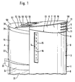
- FIGS. 1 to 3 there is the electric domestic brewing beverage machine 62 from a cold water reservoir 1 formed in the rear area, which in essentially runs from the base 2 upwards in a columnar manner and one in cross section has a substantially U-shaped outer or side surface 9.
- the Cold water storage container 1 essentially consists of an outer container part 3 and an inner container part 4 inserted into the outer container part 3.
- the inner Container part 4 protrudes with its upper one in the inserted state, that is to say in the operating position End 5, as clearly shown in FIG. 1, from the upper edge 6 of the outer container part 3 up out.
- the upper edge 6 of the outer container part 3 runs horizontally to the rear (area B) or also, as can be seen in FIGS. 1 to 3, slightly sloping backwards, during the upper edge 7 of the inner container part 4 to the front (in direction A) to the household brewing beverage machine 62 sloping so that the between the upper Edge 6 of the outer container part 3 and the upper edge 7 of the inner container part 4 formed U-shaped disc section 8 of the inner container part 4 like a flat the piece of cake that has been put down looks like, but only if 7 of the inner container part 4, which is designed as a flat disc and is connected to the section 8 adapted lid 10 is placed and thus closes the inner container part 4. Of the Lid 10 closes with the outer edge 7 of the inner container part 4 and is itself just trained.
- Behind the disc 15 is a measuring scale 16 with numbers from 3 to 10 to recognize that are printed on the same height on the inner container part 4, as Fig. 3 shows particularly clearly.
- a filling level which is set on the measuring scale 16 (not of water indicates the amount of water in the inner container part 4 is present and what number of cups this amount after brewing results.
- the side wall 9 widens at the lower region of the outer container part 3 over the base 2 to a ring collar.
- the base 2 serves as a closed ring collar, which also encloses the front part of the household brewing beverage machine, like this is apparent from Figures 2 and 3.
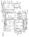
- the front end wall 18 of the inner container part 4 is concave, while the end wall 17 of the outer container part 3, adapted accordingly, is convex is.
- the filter housing adjoining the end walls 17, 18 in the front area 19 and the glass container 20 placed underneath are partially in this concave recess 21 are received.
- the majority of the filter housing 19 and the glass container 20 with their substantially semi-cylindrical shape connect to the outer container part 3 to the front as the outer surface 22, 23.
- Of the Glass container 20 also has an annular ring collar 24 on its upper edge to which a handle 25 connects.
- the glass container 20 is on a hot plate 26 placed, which are surrounded by an annular bottom portion 27 is.
- the bottom part 27 then closes at the same height as the outer container part 3 of the base 2.
- the base part 27 extends from FIGS. 1 to 3 Warming plate 26 is slightly conical downwards and ends in one cylindrical section 28.
- a semicircular cylinder closes flush and disc-shaped brewing head 30 on the lower edge has an outlet 31, as shown in dashed lines in Fig. 3.
- the outlet 31 leaves hot water in a formed in the filter housing 19 and down Flowing in conically tapering recess 32, in which one with an extraction material 33 fillable paper filter 34 is used.
- These parts are shown in dashed lines in Fig. 3, since they are not visible from the outside.
- the outlet 31 is connected via a riser 35 an electrical formed below the warming plate 26 in the bottom part 27 Water heater 36 connected, the electrical lines 37 with one at the Front (area A) trained on / off switch 38 is controllable.
- the electric one Switch 38 is also connected via a line, not shown in the drawing coming out of the brewing beverage machine 62 connecting cable connected with an electrical power supply network can be connected.
- the water heater 36 has an input line 39 according to FIG Line 40 is connected to the outlet 41.
- the outlet 41 forming the opening 61 is formed by a pipe section 40a, which integrally connects to the bottom 42 of the outer container part 3 connects down. This area was also dashed in Fig. 3 shown since it is not visible from the outside.
- In the outlet 41 engages on inner container part 4 at the bottom 43 formed tube 44, which with a Seal 45 is sealed against the housing wall of the outlet 41.
- the Seal 45 preferably consists of an O-ring, which is not in one in the drawing annular groove shown in detail is used on the pipe section 40a and held stationary. At very tight fits of outlet 41 and pipe section 44 can even with the same sealing effect the seal 45 is omitted if these surfaces are permanently greased.
- the receiving space 46 forming the bottom 42 of the inner container 4 serves as the receiving space a water filter 47, as can be seen in FIG. 3 in the inner container part 4 which has sieves (not recognizable) at its upper and lower ends, the one Allow flow of water only through the water filter 47.
- the inner container part 4 expands and forms the actual one Recording room for the cold water.
- the inner Container part 4 formed transparent, so that in addition to the water level indicator Water filter 47 is clearly visible from the outside. This is for cleaning the water a granulate 49 can be filled.
- buttons 53, 54 are rotatable, which in turn are provided with a rib 55, 56 pointing forward.
- the actuating buttons 53, 54 can, for example, be formed in the lower region in the cylindrical section 28 completely replace electrical switch 38 or they can additionally as other switches are used, for example, to operate a clock or other serve electrical devices of the household brewing beverage machine.
- the control buttons 53, 54 can also be used, for example, as actuating elements for unlocking devices serve the inner container part 3 or the filter housing 19. However, they can also advantageously be used as setting knobs for a water metering device Determination of the aroma of a brewed beverage or as a consumption indicator of the Serve water filters etc.
- the outer plane of the lid 10 lies on the same outer plane as the surface 52 of the pedestal 51.
- the lid 10 can be opened upwards on two articulated hinges 57 and has at its other end a projection 58 which opens the Lid 10 relieved by hand.
- the mode of operation of the domestic brewing beverage machine is as follows:
- the boiling water is due to the onset of steam bubbles via the riser 35 to the brewing head 30, at the outlet 31 of which it is in the paper filter which can be filled with the extraction material 33, such as ground coffee 34 flows.
- the finished brewed drink then flows at outlet 59 of the Filter housing 19 from where it flows into the glass container 20.
- After all water has passed the water heater 36, and flowed into the glass container 20 as a brewed beverage is switched on an electrical trained in the household brewing beverage machine Thermostat (not shown) from the water heater 36 and now only controls the temperature of the hot plate 26.
- the inner container part 4 can become dirty, but this is easy can be lifted out of the outer container part 3. Even if still little liquid is present in the inner container part 4, this can easily be made the outer container part 3 can be removed because when the water on the pipe section 44 flows out, gets into the outer container part 3, but which in turn via the Outlet 41 is sealingly connected to line 40. To prevent inside Container part 4 located water does not get into the outer container part 3, is between the outlet 41 and the pipe section 44 an O-ring 45 in an advantageous manner educated.
- the water filter 47 located therein can be easily removed and the Inner container part 4 can be easily from all sides in a dishwasher getting cleaned. After cleaning it, a new water filter 47 with a new one Granules 49 in (complete cartridge) the receiving space 46 can be used. Subsequently is by gripping the upper end 5 in the region of the ribs 11 of the inner container part 4 again in the receiving space 59 of the outer container part 3 used and lowered until it reaches the operating position shown in Fig. 1 has reached.
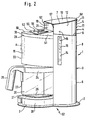
- Fig. 2 shows an intermediate position of the inner container part 4 during its Inserting into the outer container part 3.
- this is centered via its outer wall 12 on the inner wall 60 of the outer Container part 3, so that the inner container 4 by itself due to its gravity its operating position comes when the inner container part 4 is released.
- the pipe section 44 slides concentrically into the outlet 41 and seals itself over the seal 45 by itself.
- the seal 45 can also be made from one of these parts 44, 41 molded sealing lip (not shown).
Landscapes
- Engineering & Computer Science (AREA)
- Food Science & Technology (AREA)
- Physics & Mathematics (AREA)
- Thermal Sciences (AREA)
- Apparatus For Making Beverages (AREA)
Claims (11)
- Réservoir d'eau froide destiné à un appareil électroménager (62) permettant de préparer des boissons chaudes, comportant une sortie (41) d'écoulement d'eau froide contenue dans celui-ci, laquelle est amenée, après mise en route de l'appareil à préparer les boissons chaudes (62), depuis ledit réservoir vers un chauffe-eau (36) et ensuite à un produit d'extraction (33) pour préparer une boisson chaude, la sortie (41) étant en liaison d'écoulement avec le côté d'entrée d'eau (39) du chauffe-eau (36), le réservoir d'eau froide (1) étant réalisé à double paroi sur ses parois latérales et sa paroi de fond, une partie intérieure de réservoir (4) formée par les parois intérieures latérales et de fond (62, 43) étant susceptibles d'être extraite hors de la partie extérieure de réservoir (3) formée par les parois extérieures latérales et de fond (9, 42), et une ouverture (61) étant réalisée sur la partie intérieure de réservoir (4), ladite ouverture étant reliée de manière étanche avec la sortie (41) du réservoir d'eau froide lorsque la partie intérieure de réservoir (4) est mise en place dans la partie extérieure de réservoir (3), caractérisé en ce que la paroi latérale intérieure (12) de la partie intérieure de réservoir (4) fait saillie de manière différemment éloignée hors de la paroi latérale (9) de la partie extérieure de réservoir (3).
- Réservoir d'eau froide selon la revendication 1, caractérisé en ce que la partie en saillie (8) de la paroi latérale (12) de la partie intérieure de réservoir (4) est pourvue d'au moins un élément de manipulation.
- Réservoir d'eau froide selon la revendication 2, caractérisé en ce que l'élément de manipulation (11) est formé par un creux ou au moins une nervure.
- Réservoir d'eau froide selon la revendication 1, caractérisé en ce que le réservoir d'eau froide (1) est susceptible d'être fermé par un couvercle (10) posé amovible sur le bord supérieur (7) de la partie intérieure de réservoir (4)
- Réservoir d'eau froide selon la revendication 1, caractérisé en ce que sur la paroi latérale (12) de la partie intérieure de réservoir (4) est formé un épaulement (11) périphérique qui fait saillie vers l'extérieur, lequel recouvre le bord supérieur (6) de la partie extérieure de réservoir (3) lorsque la partie intérieure de réservoir (4) est mise en place.
- Réservoir d'eau froide selon la revendication 1, caractérisé en ce que la partie intérieure de réservoir (4) est transparente.
- Réservoir d'eau froide selon la revendication 5, caractérisé en ce que la partie extérieure de réservoir (3) présente une traversée (14) à travers laquelle une partie de la paroi latérale (12) de la partie intérieure de réservoir (4) est visible.
- Réservoir d'eau froide selon la revendication 6, caractérisé en ce qu'une graduation de mesure (16) est réalisée dans la paroi extérieure (12) de la partie intérieure de réservoir (4) au niveau de la traversée (14).
- Réservoir d'eau froide selon la revendication 1, caractérisé en ce que la partie extérieure de réservoir (3) présente une autre couleur que la partie intérieure de réservoir (4).
- Réservoir d'eau froide selon la revendication 1, caractérisé en ce qu'une chambre de réception (46) pour un filtre à eau (47) est réalisée sur le fond (43) de la partie intérieure de réservoir (4).
- Réservoir d'eau froide selon la revendication 1, caractérisé en ce qu'il est prévu entre les parties de réservoir intérieure (4) et extérieure (3) des moyens de blocage qui relient mécaniquement l'une à l'autre et de manière amovible les deux parties de réservoir (3, 4) lorsque la partie intérieure de réservoir (4) est mise en place dans la partie extérieure de réservoir (3).
Applications Claiming Priority (3)
| Application Number | Priority Date | Filing Date | Title |
|---|---|---|---|
| DE19504839 | 1995-02-14 | ||
| DE19504839A DE19504839C1 (de) | 1995-02-14 | 1995-02-14 | Kaltwasservorratsbehälter für eine elektrische Haushaltsbrühgetränkemaschine |
| PCT/EP1996/000439 WO1996025078A1 (fr) | 1995-02-14 | 1996-02-02 | Reservoir d'eau froide destine a un appareil electromenager permettant de preparer des boissons chaudes |
Publications (2)
| Publication Number | Publication Date |
|---|---|
| EP0809455A1 EP0809455A1 (fr) | 1997-12-03 |
| EP0809455B1 true EP0809455B1 (fr) | 1998-10-14 |
Family
ID=7753896
Family Applications (1)
| Application Number | Title | Priority Date | Filing Date |
|---|---|---|---|
| EP96903966A Expired - Lifetime EP0809455B1 (fr) | 1995-02-14 | 1996-02-02 | Reservoir d'eau froide destine a un appareil electromenager permettant de preparer des boissons chaudes |
Country Status (3)
| Country | Link |
|---|---|
| EP (1) | EP0809455B1 (fr) |
| DE (2) | DE19504839C1 (fr) |
| WO (1) | WO1996025078A1 (fr) |
Cited By (3)
| Publication number | Priority date | Publication date | Assignee | Title |
|---|---|---|---|---|
| DE102004004837A1 (de) * | 2004-01-30 | 2005-08-18 | BSH Bosch und Siemens Hausgeräte GmbH | Kaffeemaschine und Wasserbehälter für eine Kaffeemaschine |
| DE102004004822A1 (de) * | 2004-01-30 | 2005-08-18 | BSH Bosch und Siemens Hausgeräte GmbH | Kaffeemaschine und Wasserbehälter für eine Kaffeemaschine |
| RU2566475C2 (ru) * | 2011-01-17 | 2015-10-27 | Сантори Беверидж Энд Фуд Лимитед | Устройство для экстрагирования напитка |
Families Citing this family (9)
| Publication number | Priority date | Publication date | Assignee | Title |
|---|---|---|---|---|
| FR2806606B1 (fr) * | 2000-03-24 | 2002-10-25 | Moulinex Sa | Machine a cafe electrique avec reservoir d'eau pivotant |
| FR2824248B1 (fr) * | 2001-05-04 | 2006-09-01 | Seb Sa | Machine a boissons chaudes comportant un reservoir d'eau amovible |
| GB2447024A (en) * | 2007-02-27 | 2008-09-03 | Kraft Foods R & D Inc | A dispensing machine for hot or cold drinks |
| IT1392056B1 (it) * | 2008-09-19 | 2012-02-09 | De Longhi Spa | Struttura di filtro per il filtraggio dell'acqua contenuta in un serbatoio di una macchina per la produzione di caffe' |
| CN203619242U (zh) * | 2013-11-11 | 2014-06-04 | 李文钦 | 一种多功能饮水机水杯 |
| DE102015208328A1 (de) * | 2015-05-05 | 2016-11-10 | BSH Hausgeräte GmbH | Wassertank eines Getränkeautomaten |
| CN204797600U (zh) | 2015-06-24 | 2015-11-25 | 博西华电器(江苏)有限公司 | 饮料机 |
| CN108348093B (zh) * | 2015-11-11 | 2020-12-15 | 雀巢产品有限公司 | 液体罐与饮料机器的简单连接 |
| DE102016219197A1 (de) | 2016-10-04 | 2018-04-05 | BSH Hausgeräte GmbH | Tank für eine Getränkezubereitungsvorrichtung und Getränkezubereitungs-vorrichtung |
Family Cites Families (5)
| Publication number | Priority date | Publication date | Assignee | Title |
|---|---|---|---|---|
| DE3914281A1 (de) * | 1989-04-29 | 1990-10-31 | Siegfried Keusch | Elektrisch betriebenes geraet zum zubereiten von heissgetraenken, wie kaffee, tee oder dgl. |
| FR2648694B1 (fr) * | 1989-06-23 | 1991-09-20 | Seb Sa | Reservoir d'eau amovible pour appareil menager et appareil menager comportant un tel reservoir |
| DE3938446C1 (fr) * | 1989-11-18 | 1991-04-18 | Melitta Haushaltsprodukte Gmbh & Co Kg, 4950 Minden, De | |
| FR2708452B1 (fr) * | 1993-07-29 | 1997-09-05 | Moulinex Sa | Machine à infusion comportant un dispositif de purification d'eau. |
| DE9319872U1 (de) * | 1993-12-23 | 1994-03-03 | Bosch-Siemens Hausgeräte GmbH, 81669 München | Elektrische Kaffeemaschine |
-
1995
- 1995-02-14 DE DE19504839A patent/DE19504839C1/de not_active Revoked
-
1996
- 1996-02-02 WO PCT/EP1996/000439 patent/WO1996025078A1/fr active IP Right Grant
- 1996-02-02 DE DE59600672T patent/DE59600672D1/de not_active Expired - Fee Related
- 1996-02-02 EP EP96903966A patent/EP0809455B1/fr not_active Expired - Lifetime
Cited By (4)
| Publication number | Priority date | Publication date | Assignee | Title |
|---|---|---|---|---|
| DE102004004837A1 (de) * | 2004-01-30 | 2005-08-18 | BSH Bosch und Siemens Hausgeräte GmbH | Kaffeemaschine und Wasserbehälter für eine Kaffeemaschine |
| DE102004004822A1 (de) * | 2004-01-30 | 2005-08-18 | BSH Bosch und Siemens Hausgeräte GmbH | Kaffeemaschine und Wasserbehälter für eine Kaffeemaschine |
| DE102004004837B4 (de) * | 2004-01-30 | 2013-11-21 | BSH Bosch und Siemens Hausgeräte GmbH | Kaffeemaschine |
| RU2566475C2 (ru) * | 2011-01-17 | 2015-10-27 | Сантори Беверидж Энд Фуд Лимитед | Устройство для экстрагирования напитка |
Also Published As
| Publication number | Publication date |
|---|---|
| WO1996025078A1 (fr) | 1996-08-22 |
| DE19504839C1 (de) | 1996-04-04 |
| EP0809455A1 (fr) | 1997-12-03 |
| DE59600672D1 (de) | 1998-11-19 |
Similar Documents
| Publication | Publication Date | Title |
|---|---|---|
| DE19846583C2 (de) | Wasserfiltervorrichtung mit einer Auffangkanne und mit Heizelement | |
| DE3803728C2 (fr) | ||
| EP0809455B1 (fr) | Reservoir d'eau froide destine a un appareil electromenager permettant de preparer des boissons chaudes | |
| DE69407549T2 (de) | Brühverfahren | |
| DE69317455T2 (de) | Automatische Getränkebrühvorrichtung | |
| DE3436984A1 (de) | Maschine zum zubereiten heisser getraenke mit dosierter fluessigkeitsentnahme | |
| DE2851846A1 (de) | Kombinierte vorrichtung aus kaffeemaschine und kaffeemuehle | |
| EP3166452A1 (fr) | Dispositif et procédé de préparation d'une boisson infusée | |
| AT398272B (de) | Kaffeemaschine | |
| EP1468635B1 (fr) | Dispositif pour la préparation de boissons chaudes | |
| EP0867142B1 (fr) | Machine à café express | |
| DE2745959B2 (de) | Kaffeemaschine | |
| DE102006025419A1 (de) | Bewegliches Fenster am Kaffeegerätegehäuse | |
| DE102014109765A1 (de) | Verfahren und Vorrichtung zur Zubereitung eines Brühgetränks | |
| DE102015117891A1 (de) | Schmutzwasserablauf für einen Heißgetränkeautomaten | |
| DE2829775A1 (de) | Geraet zur zubereitung von tee | |
| DE69403127T2 (de) | Kaffeemaschine mit Wasserrückführungsschacht | |
| DE4124993C2 (de) | Vorrichtung zum Zubereiten von Tee | |
| CH182342A (de) | Apparat zur Herstellung von Auszügen aus Kaffee, Tee, usw. | |
| DE715730C (de) | Bruehvorrichtung fuer Kaffee mit herausnehmbarem Filtersiebbehaelter | |
| EP0053234B1 (fr) | Couvercle isolant pour un pot à café à isolation thermique | |
| DE20015710U1 (de) | Brühkopf für eine Espressomaschine | |
| DE2732053A1 (de) | Kaffeemaschine mit filter | |
| EP0011290A1 (fr) | Machine à café express | |
| DE19823546A1 (de) | Verfahren und Vorrichtungen zur Zubereitung von Kaffee |
Legal Events
| Date | Code | Title | Description |
|---|---|---|---|
| PUAI | Public reference made under article 153(3) epc to a published international application that has entered the european phase |
Free format text: ORIGINAL CODE: 0009012 |
|
| 17P | Request for examination filed |
Effective date: 19961030 |
|
| AK | Designated contracting states |
Kind code of ref document: A1 Designated state(s): DE ES FR IT NL |
|
| GRAG | Despatch of communication of intention to grant |
Free format text: ORIGINAL CODE: EPIDOS AGRA |
|
| 17Q | First examination report despatched |
Effective date: 19971217 |
|
| GRAG | Despatch of communication of intention to grant |
Free format text: ORIGINAL CODE: EPIDOS AGRA |
|
| GRAH | Despatch of communication of intention to grant a patent |
Free format text: ORIGINAL CODE: EPIDOS IGRA |
|
| GRAH | Despatch of communication of intention to grant a patent |
Free format text: ORIGINAL CODE: EPIDOS IGRA |
|
| GRAA | (expected) grant |
Free format text: ORIGINAL CODE: 0009210 |
|
| AK | Designated contracting states |
Kind code of ref document: B1 Designated state(s): DE ES FR IT NL |
|
| PG25 | Lapsed in a contracting state [announced via postgrant information from national office to epo] |
Ref country code: NL Free format text: LAPSE BECAUSE OF FAILURE TO SUBMIT A TRANSLATION OF THE DESCRIPTION OR TO PAY THE FEE WITHIN THE PRESCRIBED TIME-LIMIT Effective date: 19981014 Ref country code: IT Free format text: LAPSE BECAUSE OF FAILURE TO SUBMIT A TRANSLATION OF THE DESCRIPTION OR TO PAY THE FEE WITHIN THE PRESCRIBED TIME-LIMIT;WARNING: LAPSES OF ITALIAN PATENTS WITH EFFECTIVE DATE BEFORE 2007 MAY HAVE OCCURRED AT ANY TIME BEFORE 2007. THE CORRECT EFFECTIVE DATE MAY BE DIFFERENT FROM THE ONE RECORDED. Effective date: 19981014 Ref country code: ES Free format text: THE PATENT HAS BEEN ANNULLED BY A DECISION OF A NATIONAL AUTHORITY Effective date: 19981014 |
|
| REF | Corresponds to: |
Ref document number: 59600672 Country of ref document: DE Date of ref document: 19981119 |
|
| PGFP | Annual fee paid to national office [announced via postgrant information from national office to epo] |
Ref country code: DE Payment date: 19990122 Year of fee payment: 4 |
|
| ET | Fr: translation filed | ||
| PGFP | Annual fee paid to national office [announced via postgrant information from national office to epo] |
Ref country code: FR Payment date: 19990215 Year of fee payment: 4 |
|
| NLV1 | Nl: lapsed or annulled due to failure to fulfill the requirements of art. 29p and 29m of the patents act | ||
| PLBE | No opposition filed within time limit |
Free format text: ORIGINAL CODE: 0009261 |
|
| STAA | Information on the status of an ep patent application or granted ep patent |
Free format text: STATUS: NO OPPOSITION FILED WITHIN TIME LIMIT |
|
| 26N | No opposition filed | ||
| REG | Reference to a national code |
Ref country code: FR Ref legal event code: CD Ref country code: FR Ref legal event code: CA |
|
| PG25 | Lapsed in a contracting state [announced via postgrant information from national office to epo] |
Ref country code: FR Free format text: LAPSE BECAUSE OF NON-PAYMENT OF DUE FEES Effective date: 20001031 |
|
| PG25 | Lapsed in a contracting state [announced via postgrant information from national office to epo] |
Ref country code: DE Free format text: LAPSE BECAUSE OF NON-PAYMENT OF DUE FEES Effective date: 20001201 |
|
| REG | Reference to a national code |
Ref country code: FR Ref legal event code: ST |