EP0809377B1 - Signalerfassung in einer Satellitenübertragungsanordnung - Google Patents
Signalerfassung in einer Satellitenübertragungsanordnung Download PDFInfo
- Publication number
- EP0809377B1 EP0809377B1 EP97660057A EP97660057A EP0809377B1 EP 0809377 B1 EP0809377 B1 EP 0809377B1 EP 97660057 A EP97660057 A EP 97660057A EP 97660057 A EP97660057 A EP 97660057A EP 0809377 B1 EP0809377 B1 EP 0809377B1
- Authority
- EP
- European Patent Office
- Prior art keywords
- frequency
- signal
- calculated
- sample sequence
- frame
- Prior art date
- Legal status (The legal status is an assumption and is not a legal conclusion. Google has not performed a legal analysis and makes no representation as to the accuracy of the status listed.)
- Expired - Lifetime
Links
- 238000000034 method Methods 0.000 claims description 52
- 238000012937 correction Methods 0.000 claims description 36
- 230000005855 radiation Effects 0.000 claims description 20
- 239000000523 sample Substances 0.000 description 40
- 230000005540 biological transmission Effects 0.000 description 11
- 238000004891 communication Methods 0.000 description 10
- 238000004364 calculation method Methods 0.000 description 9
- 238000005070 sampling Methods 0.000 description 6
- 238000012545 processing Methods 0.000 description 5
- 238000004088 simulation Methods 0.000 description 4
- 238000001228 spectrum Methods 0.000 description 4
- 238000001514 detection method Methods 0.000 description 3
- 238000010586 diagram Methods 0.000 description 3
- 239000000203 mixture Substances 0.000 description 3
- 230000001020 rhythmical effect Effects 0.000 description 3
- 238000007792 addition Methods 0.000 description 2
- 230000015572 biosynthetic process Effects 0.000 description 2
- 238000006243 chemical reaction Methods 0.000 description 2
- 230000002349 favourable effect Effects 0.000 description 2
- 238000012986 modification Methods 0.000 description 2
- 230000004048 modification Effects 0.000 description 2
- 238000012935 Averaging Methods 0.000 description 1
- 239000000654 additive Substances 0.000 description 1
- 230000000996 additive effect Effects 0.000 description 1
- 230000003321 amplification Effects 0.000 description 1
- 239000000969 carrier Substances 0.000 description 1
- 239000012141 concentrate Substances 0.000 description 1
- 230000006866 deterioration Effects 0.000 description 1
- 230000003292 diminished effect Effects 0.000 description 1
- 230000000694 effects Effects 0.000 description 1
- 230000008030 elimination Effects 0.000 description 1
- 238000003379 elimination reaction Methods 0.000 description 1
- 238000005516 engineering process Methods 0.000 description 1
- 238000001914 filtration Methods 0.000 description 1
- 230000006870 function Effects 0.000 description 1
- 230000002452 interceptive effect Effects 0.000 description 1
- 230000001788 irregular Effects 0.000 description 1
- 238000003199 nucleic acid amplification method Methods 0.000 description 1
- 230000010363 phase shift Effects 0.000 description 1
- 230000011664 signaling Effects 0.000 description 1
- 230000001360 synchronised effect Effects 0.000 description 1
Images


Classifications
-
- H—ELECTRICITY
- H04—ELECTRIC COMMUNICATION TECHNIQUE
- H04L—TRANSMISSION OF DIGITAL INFORMATION, e.g. TELEGRAPHIC COMMUNICATION
- H04L7/00—Arrangements for synchronising receiver with transmitter
- H04L7/04—Speed or phase control by synchronisation signals
- H04L7/041—Speed or phase control by synchronisation signals using special codes as synchronising signal
- H04L7/042—Detectors therefor, e.g. correlators, state machines
-
- H—ELECTRICITY
- H04—ELECTRIC COMMUNICATION TECHNIQUE
- H04B—TRANSMISSION
- H04B7/00—Radio transmission systems, i.e. using radiation field
- H04B7/14—Relay systems
- H04B7/15—Active relay systems
- H04B7/185—Space-based or airborne stations; Stations for satellite systems
- H04B7/1853—Satellite systems for providing telephony service to a mobile station, i.e. mobile satellite service
- H04B7/18532—Arrangements for managing transmission, i.e. for transporting data or a signalling message
-
- H—ELECTRICITY
- H04—ELECTRIC COMMUNICATION TECHNIQUE
- H04L—TRANSMISSION OF DIGITAL INFORMATION, e.g. TELEGRAPHIC COMMUNICATION
- H04L7/00—Arrangements for synchronising receiver with transmitter
- H04L7/02—Speed or phase control by the received code signals, the signals containing no special synchronisation information
- H04L7/027—Speed or phase control by the received code signals, the signals containing no special synchronisation information extracting the synchronising or clock signal from the received signal spectrum, e.g. by using a resonant or bandpass circuit
-
- H—ELECTRICITY
- H04—ELECTRIC COMMUNICATION TECHNIQUE
- H04L—TRANSMISSION OF DIGITAL INFORMATION, e.g. TELEGRAPHIC COMMUNICATION
- H04L7/00—Arrangements for synchronising receiver with transmitter
- H04L7/0054—Detection of the synchronisation error by features other than the received signal transition
- H04L7/007—Detection of the synchronisation error by features other than the received signal transition detection of error based on maximum signal power, e.g. peak value, maximizing autocorrelation
Definitions
- the invention relates in general to the operation of a receiver in order to find the electric signal to be received, and in particular to the utilisation of a control signal provided in a predetermined rhythmic pattern in a situation where the receiver must find the signal among several possible frequencies and synchronise the reception according to the signal properties.
- the receiver In such radio communications systems that have several data transmission frequencies and variable uses with respect to area and/or time, the receiver must, prior to beginning the reception proper, find the desired signal and synchronise its operation in order to interpret the content of the signal. Finding the signal means that the receiver is tuned to exactly that frequency where the signal is located. In the synchronisation process the receiver must find out where each separate symbol pertaining to the signal begins, and at what rate the signals succeed to each other.
- the present application pays special attention to the I-CO Global Communications satellite telephone system, which is based on ten communications satellites with a so-called medium-high orbit (roughly 10,000 km).
- the satellites orbit the earth at regular intervals on two mutually perpendicular orbits with an inclination of 45°.
- Each satellite comprises an antenna arrange-ment with a power pattern of 121 narrow radiation lobes, which together cover the coverage area of said satellite on earth.
- the coverage area means the whole area from which the satellite is seen more than 10 degrees above the horizon.
- the operational frequency range of the system is roughly 2 GHz, and it utilises TDMA, Time Division Multiple Access.
- the system defines a so-called CCS carrier (Common Channel Signalling), which means a given carrier frequency reserved for signal acquisition, synchronisation and distribution of general communications information.
- CCS carrier Common Channel Signalling
- a receiver located on earth or near the surface of the earth stores the eight location-connected local CCS frequencies to a non-volatile memory; consequently, when it is switched off and back on, it searches a signal from among said eight frequencies. If a signal is not found, the receiver next studies the 40 regional frequencies, and if there still is no signal, finally all 120 global frequencies.
- a transmission with each CCS frequency consists of several multiframes 10, which are divided into 25 slots 11.
- Each slot includes 120 symbols 12.
- the symbol rate in the system is 18,000 symbols per second, but it may be increased to 36,000 symbols per second in the future.
- the first slot in the frame comprises a BCCH (Broadcast Control Channel) burst 13, which is BPSK (Binary Phase Shift Keying) modulated and contains, among others, communications data and a 32 symbols long reference sequence 14, which is important for synchronisation.
- BCCH Broadcast Control Channel
- BPSK Binary Phase Shift Keying
- Two successive slots contain a FCH (Frequency Channel) burst 15, which is transmitted with a somewhat lower frequency than the BCCH burst and consists of pure sinus wave at the frequency of said CCS carrier; the purpose of said FCH burst 15 is to aid the synchronisation of the receiver.
- FCH Frequency Channel
- Other slots in the CCS carrier are empty.
- the receiver For successful reception, the receiver must, after being switched on, first find the desired signal.
- General criteria for the signal to be found is that the timing error in the reception is ⁇ 1 ⁇ 2 symbols at the most, and that the frequency error is no more than a few percentages of the symbol rate. The nearer to zero these two error factors are, the smaller the probability that bit errors happen in the reception, and the less the reception is sensitive to the deterioration of the S/N ratio.
- the receiver observes the power profile in the frame scale with the found CCS frequency and assumes that the peak of the power profile corresponds to a BCCH burst. Thereafter the receiver picks a discrete sample series of the FCH burst and calculates therefrom a 128-sample long fast Fourier transform (FFT), the results of which are used in the coarse correction of frequency error.
- FFT long fast Fourier transform
- EP-A-0 632 606 (NIPPON ELECTRIC CO) of 4 January 1995 is known to disclose an apparatus and method for establishing frame synchronization in a satellite communication system which receives a modulated signal having frames. A unique word and data are multiplexed in each of the frames.
- a demodulator demodulates the modulated signal and provides a demodulated signal including the unique words.
- a signal detector compares the signal power of the demodulated signal with a threshold signal and provides a detection signal.
- a selector provides, in accordance with the detection signal, the detected demodulated signal or fixed data as a selected signal.
- a frame synchronizing circuit detects the unique word from the selected signal, when the demodulated signal is provided as the selected signal by the selector, and establishes frame synchronization in accordance with the detected unique word.
- the object of the present invention is to introduce a method for signal acquisition, frame synchronisation and elimination of frequency errors in a multi-frequency communications system by utilising a transmission which is in advance arranged to a certain rhythmic pattern on a given control channel.
- Another object of the invention is to achieve a system which operates quickly and reliably in varying reception conditions and can adapt itself to changing conditions.
- the method according to the invention is characterised in that it comprises steps where
- the method of the invention proceeds step by step. Samples are picked of received radiation on a given carrier frequency, mixed to the baseband and filtered, and each of said samples corresponds to one symbol as for duration.
- the receiver device records complex samples for the length of two frames and one slot and slides over them an estimation window having the length of one slot. Sliding is carried out in steps of one symbol, and every step produces a sample value which is the average of the single samples located in the window at each point of time.
- the result of the estimation is a convolution of the sample sequence and a unit function having the length of one slot, and this convolution is described with discrete values of the size of one symbol.
- the receiver selects two highest power values from both recorded frames - presupposing that the two selected values are not located at immediately adjacent points of time, but there is a certain distance in between. The significance of this distance and the realisation of the selection process are explained in more detail below. If among the four chosen values there are found two with a mutual distance that corresponds to the frame length with sufficient accuracy, the receiver maintains that it has found in the frame the location of a regularly repeated high-power burst (in the above mentioned CCS carrier this means a BCCH burst). The found location is called the frame synchronisation point.
- the receiver adjusts the automatic amplification level to be such that the average obtained for said two power peaks is equal to a nominal target value defined for the reception.
- power average the sum of the power values located in the estimation window and divided by the number of said values
- the receiver calculates the signal level by subtracting said noise level from the average of said two power peaks.
- the signal to noise ratio is defined as the quotient of the signal level and the noise level.
- the receiver decides, on the basis of the signal to noise ratio, whether more frequency data must be received in order to estimate the frequency error.
- the signal to noise ratio is sufficiently good, and the receiver decides, on the basis of the detected high-power burst, which part of the recorded sample sequence describes frequency data contained in the transmission, and calculates a discrete fast Fourier transform on the basis of this.
- the obtained result is a given frequency spectrum, where the frequency point corresponding to the highest power value describes a frequency deviation from a desired frequency. If the frequency deviation is smaller than a given threshold value, advantageously one percentage of the symbol rate, the recorded sample sequence is accepted without corrections as a basis for the next step in the method.
- the receiver compensates by calculatory means the phase rotation which was caused in the samples of the recorded sample sequence owing to the frequency error.
- the receiver corrects the mixing frequency for the quantity of the frequency deviation and receives, mixes, filters and records two new signal lengths, each of which comprises the reference sequence of one BCCH as well as additional 30 samples at the beginning and end thereof.
- the found location of the frame synchronisation point is adjusted so that the error is no more than ⁇ 1 ⁇ 2 symbols.
- the receiver selects an area that extends, for the length of a given error margin, to both directions from the earlier calculated frame synchronisation point.
- the estimation window of a given length is slided over the selected area, so that there are obtained two separate sequences of estimate values.
- the receiver does not obtain an unambiguous synchronisation result, it concludes that there is no transmission at the carrier frequency in question, and continues searching at another carrier frequency.
- the first and foremost frequencies are those local frequencies that the receiver assumes to be used within its range of location. If a signal is not found, the search proceeds first to regional and then to global frequencies.
- FIG. 2 is a schematic flow diagram describing how the method according to the invention proceeds step by step.
- the receiver attempts a coarse frame synchronisation at a given carrier frequency by detecting local power peaks in the recorded sample sequence and by comparing their mutual location.
- the decision-making step 21 the receiver checks whether the coarse frame synchronisation has succeeded. If there is no receivable signal at the carrier frequency in question, the frame synchronisation fails and the receiver shifts to mode 22, where it selects another carrier frequency. If the coarse frame synchronisation has succeeded, the method of the invention proceeds to step 23, where the receiver calculates the discrete Fourier transform by using as initial data such part of the recorded sample sequence that contains frequency data connected to the carrier frequency in question.
- the number of the Fourier transforms to be calculated depends on the signal to noise ratio in a way that will be explained below.
- the step 24 of the method of the invention comprises an adjusted frame synchronisation, which makes use of the frequency correction rendered by the Fourier transforms, and where the location of the frame synchronisation point is attempted to be adjusted at the accuracy of half a symbol.
- the receiver checks whether the adjusted frame synchronisation has succeeded. If not, the result is a mode 26 similar to the mode 22 - where a new carrier frequency is chosen. After successful adjusted frame synchronisation, the receiver can start reception and tracking in step 27.
- Figure 3a is a schematic illustration of a sample sequence 30, received and stored by the receiver device, with a length of two frames and one slot, in which sequence the sampling ratio is 1/1, i.e. the sequence contains as many samples as two frames and one slot contain symbols.
- the detailed creation of the samples will be dealt with later on.
- the sample sequence is essentially a series of measured values of received radio power, and its composition is affected both by received transmission and noise.
- Figure 3a also illustrates an estimation window 31, the length whereof is advantageously equal to the length of one slot (here 120 symbols), and which is slided past the sample sequence 30 at one-symbol-long steps.
- the obtained result is a number sequence 32, which here is called an estimate sequence and which contains as many estimates as there are symbols in two frames, but each estimate is an average of 120 successive samples (assuming that one slot contains 120 symbols). If the received sample sequence 30 would only contain received signal, with a one-slot-long BCCH burst and a successive lower-power, two-slot-long FCH burst, the descriptor of the estimate sequence would consist of two bulges 33 and 34 formed of broken lines as illustrated in figure 3b.
- the power peak with both broken lines 33 and 34 is the estimate during the formation whereof a whole BCCH burst has been in the estimation window.
- noise has accumulated in the signal while it has proceeded on the radio path, and the estimate sequence descriptor may look fairly irregular, as is the case in figure 3c.
- the relative length of the broken lines 33 and 34 is exaggerated in comparison with the length of the part 1 - F or F + 1 -2F corresponding to one frame in the descriptor of the estimate sequence.
- the estimates can be numbered for reference for instance from 1 to 2F, where F is the number of estimates corresponding to one frame. Now the numbers from 1 to F refer to the first frame, and the numbers from F + 1 to 2F refer to the second frame.
- the receiver detects, according to a preferred embodiment of the invention, in the area of both frames first the largest estimate and thereafter the next largest such estimate which is located at the distance of at least P1 from the largest estimate.
- the critical value P1 can be for instance a distance corresponding to the length of 50 samples.
- the receiver assumes that at least two of the thus obtained four values correspond to the power peak of two successive BCCH bursts, in which case the two other values are caused by noise.
- the values corresponding to the power peaks must be located at a distance of F ⁇ P1 samples from each other.
- P1 the size of the critical value P1 is defined experimentally, because the lower the value of P1, the more accurately the power peaks must be identified irrespective of the noise accumulated in the signal. Respectively, the larger is P1, the easier it is to interpret two estimate peaks caused by pure noise to be power peaks caused by the signal.
- an advantageous P1 value is the above mentioned distance corresponding to the length of 50 samples.
- estimate 35, 36, 37 and 38 there are selected estimates 35, 36, 37 and 38.
- Estimate 39 is not chosen, although it corresponds to a higher power value than estimate 36, because it is located at a distance less than ⁇ P1 from the largest estimate 35 of the first frame.
- the distances between the selected estimates 35 - 38 are compared in order to detect whether there is found a pair with a mutual distance within the range (F-P1; F+P1), borders included.
- the estimates 35 and 38 form such a pair.
- a given order which can be for instance as follows:
- the receiver selects the average of the locations of estimates 35 and 38 as a so-called frame synchronisation point. Moreover, the receiver calculates the average of the reception power indicated by these two estimates and adjusts the automatic gain control (AGC), included in the receiver circuits in a known fashion, so that the average of said reception power, as amplified by the determined gain control, gives a certain nominal power as a result.
- AGC automatic gain control
- the receiver further calculates the signal power, noise power and the signal to noise ratio according to the procedure described above, or according to some other suitable calculation method.
- Table 1 illustrates results from a calculatory simulation, where to the signal there is fed additive white gaussian noise (AWGN) in amounts that correspond to various signal to noise ratios (S/N); it is examined how large is the percentage of all attempts where the signal frame synchronisation is missed or false.
- AWGN additive white gaussian noise
- S/N signal to noise ratios
- the distance P2 is significant in step 23 of the method according to the invention, in which step the receiver calculates the frequency correction by utilising the frequency data contained in the received signal. If the error in the frame synchronisation point is no more than P2 symbols and the frequency data is included, in a known fashion, to a given received symbol sequence, it is recommendable to ignore P2 symbols at both ends of the sequence. Frequency correction is calculated from the received samples and not from the estimates, because estimation destroys frequency data.
- the receiver has recorded in the memory samples from two frames and one slot, altogether 6120 samples. It can be assumed that among these, the first is located in memory address E, and the calculated address of the frame synchronisation point is at a distance of D symbols from the beginning of the recorded sequence.
- the address of a first memory location wherefrom there is read a sample for calculating the frequency correction is E + D + the length of one slot (i.e. 120) + error margin P2.
- E + D + the length of one slot (i.e. 120) + error margin P2 the length of one frame (i.e. 3,000).
- the length of one FCH burst is 240 symbols, for calculating the frequency correction, there is read 240 - (2*P2) samples starting from the initial memory location. Because the recorded sample sequence is two frames long, it also contains another FCH burst, the reading whereof is started one frame length later.
- one memory location corresponds to one sample, and thus to one symbol (when the sampling ratio is 1/1); therefore it is obvious for a man skilled in the art that distances between samples can be treated as time units as well as memory addresses.
- the distance in time of two samples is the same as the difference of the respective memory addresses multiplied by the known duration of one symbol. The same applies for the above mentioned estimates. If the receiver device deals with the memory locations in other than direct successive order, this must be taken into account, when the distances between memory locations are transformed to distances in time or vice versa.
- the receiver reads, for calculating frequency correction, 180 samples starting with the memory location explained above, and another set of 180 samples starting one frame length further.
- the discrete Fourier transform used in the calculation of frequency correction can in known circuit arrangements be carried out with 128 or 256 samples; thus the alternatives are either to further eliminate read samples, so that only 128 samples remain from each sequence, or to use padding as the rest of the values in the 256-sample Fourier transform. Simulation has shown that the latter alternative, i.e. adding zeroes to serve as samples 181 - 256 gives better results.
- the receiver calculates the Fourier transform separately for both FCH sample sequences read from the memory.
- the reliability of frequency correction can be remarkably improved by receiving and mixing to baseband yet one additional sample sequence, from which there are read the 180 samples corresponding to a FCH burst in similar fashion as was described above, in relation to earlier recorded sample sequences.
- For the third sample sequence there is likewise calculated a separate Fourier transform, as above. Respectively, in particularly good communication conditions, even one Fourier transform may suffice. If more than one Fourier transforms are calculated, they are averaged frequency component by component in order to reduce the effect of random errors.
- results of Fourier transforms can be slidably averaged by two, in order to bring out more clearly than before the FCH frequency possibly distributed evenly to adjacent frequency components, but this did not appear to be remarkably useful in connection with the 256-sample Fourier transform.
- the AWGN channel means a channel where the influence of multipath transmission propagation is not significant, but the interference is mainly due to gaussian noise. In the Ricean type channel, multipath transmission propagation is a remarkable interference factor.
- the result from the Fourier transform and possible averaging is a discrete frequency spectrum from -9 kHz to 9 kHz.
- the receiver detects in the spectrum the frequency component with the highest power value. This frequency represents the frequency deviation between the real FCH frequency and the frequency used in the baseband mixing. If the deviation is less than one percentage of the symbol rate, the calculation can be continued on the basis of recorded samples without calculatory corrections. The limit of one percent is defined through experimentation, and it can be replaced with some other critical value. If the deviation is within the range of 1 % - 10 % of the symbol rate, the receiver calculates the resulting phase error per symbol in radians by multiplying the frequency deviation with 2 ⁇ and by dividing the obtained product by the symbol rate.
- phase error contained in the recorded symbols and caused by the frequency deviation can be corrected by calculatory means.
- 10 percent limit is found by experimentation and can be replaced by some other critical value.
- Information contained in samples recorded with larger deviations is, owing to erroneous mixing frequency, too distorted for further processing, wherefore the receiver must correct the mixing frequency (by subtracting from the original mixing frequency the frequency deviation given by the Fourier spectrum) and receive, mix and record a number of samples corresponding to two new reference sequences of the BCCH burst. Owing to the error margin observed in the calculation of the frame synchronisation point, new data must be recorded for the amount of P2 samples in addition to the reference sequences of the assumed BCCH bursts, both at the beginning and end of said bursts.
- the receiver tries to reduce the synchronisation error from P2 (30 symbols) to the required ⁇ 1 ⁇ 2 symbols, by searching in the recorded BCCH bursts a point which best correlates with the known reference sequence.
- the reference sequence is a certain 32 symbols long repeated symbol sequence with a known location within the BCCH burst.
- the correct form of the reference sequence is stored, as a 32 symbols long sequence, in the non-volatile memory of the receiver. Irrespective of whether the receiver uses samples that were recorded earlier or has received new samples after frequency correction, it detects, on the basis of the known location of the calculated frame synchronisation point and the reference sequence, the assumed starting point of the reference sequence in each BCCH burst.
- part of the sample sequence is represented as a line 40
- the assumed starting point of the reference sequence is represented as an arrow 41.
- the correlation comparison is started, according to figure 4a, from sample 42, which is located at P2 symbols before the assumed starting point 41 of the reference sequence.
- the receiver multiplies, according to figure 4a, this complex sample 42 with the first symbol 43a of the known reference sequence 43, the next sample with the next symbol of the known reference sequence, and so on throughout the whole length of the known reference sequence.
- the obtained complex products are added up, and the power of this sum is calculated and stored.
- the known reference sequence is shifted, according to figure 4b, one symbol length further in relation to the sample sequence 40, and the same multiplication, addition and power calculation procedure is repeated.
- the correlation calculations according to figures 4a - 4c are carried out separately for both observed BCCH bursts.
- the highest of the obtained power values corresponds to that point in the sample sequence 40 where a sequence of 32 successive samples best corresponds to a known reference sequence.
- the distance of this point from the earlier calculated nominal starting point of the reference sequence should be identical in both observed BCCH bursts. If the difference of the distances calculated on the basis of separate bursts is -1, 0 or 1 symbol, it can be assumed that the correct location of the reference sequence is found.
- the value 0 of the difference naturally means that a sequence with the highest power value is found in both bursts at exactly the same point with respect to the calculated frame synchronisation point.
- the difference -1 or 1 corresponds to a situation where the locations of the reference sequence calculated on the basis of separate BCCH bursts differ for one symbol to either direction. This may be due to the fact that in the A/D conversion, connected to the processing of the received signal in a known fashion, the border of the digital sampling window falls very near to the middle of a received real symbol, in which case incidental error factors define to which side of the border of said sampling window the power used for transmitting said real symbol is predominantly directed.
- the frame synchronisation has failed.
- the reason in the background can be one of the following:
- the estimate corresponding to the highest power value is chosen as the frame synchronisation point, and by means of that, there is detected a nominal starting point for the FCH burst; starting from this (subtracted by the safety margin P2), the frequency samples are read in order to calculate the Fourier transform. If the calculated frequency error proves out to be larger than one percent of the symbol rate, the receiver corrects the mixing frequency and receives a new BCCH burst. Thereafter the receiver calculates from the frame synchronisation point the starting point of the reference sequence and detects a more accurate frame synchronisation by studying the correlation of successive symbol sequences with the known reference sequence. The single shot acquisition saves some time and signal processing capacity, if the reception conditions are sufficiently good.
- the receiver If the receiver first attempts a single shot acquisition, but then decides that the signal to noise ratio is too bad, it must receive, filter, mix and record new sample sequences, which means that there is used more time than if at least two bursts were used as the basis for calculations already in the first attempt.
- the target of observation can also be some other amount of power peak values than the above mentioned two values per frame.
- the receiver can select nearly any number of peak values and use any combination in order to find a pair where the mutual order of the values corresponds, with desired accuracy, to the length of one frame. It is, however, pointed out that the larger the group of values that is chosen as the starting point in the selection of the frame synchronisation point, the higher the probability that some sudden power peak caused by noise is erroneously interpreted as a BCCH burst.
- the receiver can first process side by side two different signals synchronised according to different frame synchronisation points, whereafter that frame synchronisation point which gives better results is chosen as the final point.
- Another alternative is to shift the above mentioned digital sampling window forward or backward for half a symbol and then to study whether this improves the signal quality. If the shift took place in a wrong direction, the frame synchronisation point is shifted to the opposite direction for the length of one whole symbol.
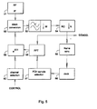
- FIG. 5 illustrates in block diagram a radio receiver 50, where the radio frequency and intermediate frequency parts represent the state of the art and are illustrated as one block 51 only.
- the intermediate frequency part produces at its output a signal which is mixed to baseband in the downconversion block 52, which essentially contains an A/D converter and a digital mixer (not illustrated separately in the drawing).
- the downconversion block 52 which essentially contains an A/D converter and a digital mixer (not illustrated separately in the drawing).
- the output of block 52 contains an eightfold number of samples as compared to the known symbol rate of the signal.
- the blocks 53 and 54 comprise underpass filtering and decimation parts, which remove interfering frequencies from the signal and reduce oversampling, until there is only one sample per symbol left in the signal.
- the frame synchronisation block 55 comprises parts corresponding to the above (in figure 2) described steps 20, 21, 24 and 25, which parts implement the frame synchronisation.
- the clock block 56 controls the synchronisation of the operation and for instance counts received symbols, even when they are not properly processed owing to the time used in the synchronisation process, so that the location of the frame synchronisation point after detection is up to date in relation to the received signal stream, irrespective of the length of time used in the frame synchronisation.
- the clock block 56 also gives the synchronisation data for the windowing block 57, which determines which samples are selected as the basis for calculating the Fourier transforms.
- the block 58 calculates the Fourier transforms (FFT) proper, and on the basis of the obtained results, the mixing frequency in block 59 is adjusted.
- the formation of the mixing frequency is part of the channel selection, which is controlled by the control block CTRL of the whole system by intermediation of the channel selection block 60.
- the signal to be demodulated is picked, after finding the frame synchronisation, from between the decimation block 54 and the frame synchronisation block 55.
- DSP digital signal processor
- the method according to the invention introduces a quick and reliable way for signal acquisition in a system where the receiver must find the signal from a group of several frequencies and synchronise to the signal by means of the rhythmic pattern of the transmission in a known control channel.
- the method requires that only about 6.000 samples are recorded for processing, which does not set inordinate demands for the equipment.
- the method according to the invention is also easily suited for various different reception environments, because the number of recorded and treated signal frames can be varied according to the prevailing signal to noise ratio.
Landscapes
- Engineering & Computer Science (AREA)
- Computer Networks & Wireless Communication (AREA)
- Signal Processing (AREA)
- Physics & Mathematics (AREA)
- Astronomy & Astrophysics (AREA)
- Aviation & Aerospace Engineering (AREA)
- General Physics & Mathematics (AREA)
- Radio Relay Systems (AREA)
- Mobile Radio Communication Systems (AREA)
- Synchronisation In Digital Transmission Systems (AREA)
Claims (14)
- Verfahren zum Erfassen eines Signals in einem Empfänger, wobei das Signal in einem gegebenen Kanal enthalten ist und umfasst:dadurch gekennzeichnet, dass es die Schritte umfasst, bei deneneinen Steuerdatenblock (13), der in regelmäßigen Intervallen in einer gegebenen Rahmenperiode (10) wiederholt wird und eine Referenzfolge (14) mit einer vorgegebenen Form enthält, undin Zuordnung zu jedem Steuerdatenblock einen Frequenzdatenteil (15), der einen niedrigeren Leistungspegel als der Steuerdatenblock (13) hat,Strahlung mit einer bestimmten Frequenz empfangen wird,in der empfangenen Strahlung ein erster Leistungspeak (35) und ein zweiter Leistungspeak (38) erfasst werden,falls die gegenseitige Zeitdifferenz zwischen dem ersten und dem zweiten Leistungspeak im Bereich [F - P1, F + P1] liegt, wobei F der Rahmenperiode entspricht und P1 ein bestimmter erster Fehler ist, eine vorläufige Entscheidung (21), dass das Signal gefunden wurde, getroffen wird,auf der Grundlage des zeitlichen Ortes des ersten und des zweiten Leistungspeaks ein gegebener zeitlicher Rahmensynchronisationspunkt definiert wird (24),ein Frequenzfehler beim Empfang der Strahlung geschätzt wird und dann, wenn der geschätzte Frequenzfehler angibt, dass der Frequenzfehler korrigiert werden muss, eine Frequenzfehlerkorrektur ausgeführt wird,auf der Grundlage des Rahmensynchronisationspunkts in der empfangenen Strahlung ein erster Teil und ein zweiter Teil, die der Referenzfolge (43) entsprechen, erfasst werden,durch das Kreuzkorrelationsverfahren mit der bekannten Form der Referenzfolge (43) der zeitliche Ort der dem ersten Teil entsprechenden besten Korrelation in Bezug auf den Rahmensynchronisationspunkt und der zeitliche Ort der dem zweiten Teil entsprechenden besten Korrelation in Bezug auf den Rahmensynchronisationspunkt erfasst werden undfalls sich der zeitliche Ort der dem ersten Teil entsprechenden besten Korrelation von dem zeitlichen Ort der dem zweiten Teil entsprechenden besten Korrelation in Bezug auf den Rahmensynchronisationspunkt um nicht mehr als die Länge eines gegebenen zweiten Fehlers unterscheidet, eine endgültige Entscheidung (25), dass das Signal gefunden wurde, getroffen wird.
- Verfahren nach Anspruch 1, dadurch gekennzeichnet, dass auf der Grundlage des zeitlichen Ortes des Rahmensynchronisationspunkts in der empfangenen Strahlung außerdem ein dritter Teil erfasst wird, der dem Frequenzdatenteil (15) entspricht, und auf der Grundlage der Inhalte des dritten Teils der Frequenzfehler zwischen der beim Empfang verwendeten Frequenz und der wirklichen Frequenz des Signals anhand der Inhalte des dritten Teils definiert wird (23).
- Verfahren nach Anspruch 2, dadurch gekennzeichnet, dass auf der Grundlage des zeitlichen Ortes des Rahmensynchronisationspunkts in der empfangenen Strahlung außerdem ein vierter Teil, der dem Frequenzdatenteil (15) entspricht, erfasst wird und auf der Grundlage der Inhalte des dritten Teils und des vierten Teils der Frequenzfehler zwischen der beim Empfang verwendeten Frequenz und der wirklichen Frequenz des Signals definiert wird.
- Verfahren nach einem der vorhergehenden Ansprüche, dadurch gekennzeichnet, dass für die Erfassung des ersten und des zweiten Leistungspeaks die empfangene Strahlung nach wenigstens vier Leistungspeaks (35, 36, 37, 38) durchsucht wird, wobei gefordert wird, dass von diesen keine zwei Leistungspeaks zeitlich näher als ein gegebener erster Grenzwert (P1) beisammen liegen.
- Verfahren nach Anspruch 4, dadurch gekennzeichnet, dass der erste Grenzwert gleich dem ersten Fehler (P1) ist.
- Verfahren nach Anspruch 1, bei dem die Rahmenperiode außerdem in eine vorgegebene Anzahl von Schlitzen (11) mit einer Standardlänge unterteilt wird und der Steuerdatenblock (13) die Länge eines Schlitzes besitzt, dadurch gekennzeichnet, dass für die in Anspruch 1 beschriebenen Schritte eine Strahlungsfolge, die im Wesentlichen die Länge von zwei Rahmen und einem Schlitz hat, in Form von Abtastwerten empfangen, gefiltert, in das Grundband gemischt und aufgezeichnet wird.
- Verfahren nach Anspruch 6, dadurch gekennzeichnet, dass für die Suche nach dem ersten und dem zweiten Leistungspeak in den aufgezeichneten Daten eine Anzahl von Schätzwerten (32) berechnet wird, wovon jeder Schätzwert ein gleitender Leistungsdurchschnitt aus N aufeinander folgenden Abtastwerten ist, wobei N die Anzahl der pro Schlitz aufgezeichneten Abtastwerte ist, und die Anzahl von Schätzwerten (32) in Schätzwerte, die anhand der ersten Rahmenperiode berechnet werden, und in Schätzwerte, die anhand der zweiten Rahmenperiode berechnet werden, unterteilt wird, wobei in diesem Fall der erste und der zweite Leistungspeak so gewählt werden, dassunter den anhand der ersten Rahmenperiode berechneten Schätzwerten der größte Schätzwert (35) und jener nächstgrößte Schätzwert (36), dessen Abstand von dem größten Schätzwert nicht länger als der erste Fehler (P1) ist, gewählt werden,unter den anhand der zweiten Rahmenperiode berechneten Schätzwerten der größte Schätzwert (38) und jener nächstgrößte Schätzwert (37), dessen Abstand vom größten Schätzwert länger als der erste Fehler ist, gewählt werden,unter den gewählten vier Schätzwerten jene zwei Schätzwerte (35, 38) ausgewählt werden, deren gegenseitige zeitliche Differenz im Bereich [F - P1, F + P1] liegt.
- Verfahren nach Anspruch 7, dadurch gekennzeichnet, dass für die Auswahl der zwei Schätzwerte, deren gegenseitige zeitliche Differenz in dem Bereich [F - P1, F + P1] liegt, die vier gewählten Schätzwerte paarweise in der folgenden Reihenfolge verglichen werden:der größte Schätzwerte (35), der anhand der ersten Rahmenperiode berechnet wird, und der größte Schätzwert (38), der anhand der zweiten Rahmenperiode berechnet wird, und als Nächstes, falls erforderlich,der größte Schätzwert (35), der anhand der ersten Rahmenperiode berechnet wird, und der zweitgrößte Schätzwert (37), der anhand der zweiten Rahmenperiode berechnet wird, und als Nächstes, falls erforderlich,der zweitgrößte Schätzwert (36), der anhand der ersten Rahmenperiode berechnet wird, und der größte Schätzwert (38), der anhand der zweiten Rahmenperiode berechnet wird, und als Nächstes, falls erforderlich,der zweitgrößte Schätzwert (36), der anhand der ersten Rahmenperiode berechnet wird, und der zweitgrößte Schätzwert (37), der anhand der zweiten Rahmenperiode berechnet wird, und als Nächstes, falls erforderlich,der größte (35) und der zweitgrößte Schätzwert (36), die anhand der ersten Rahmenperiode berechnet werden, und als Nächstes, falls erforderlich,der größte (38) und der zweitgrößte Schätzwert (37), die anhand der zweiten Rahmenperiode berechnet werden.
- Verfahren nach Anspruch 6, dadurch gekennzeichnet, dass auch ein Signal/Rausch-Verhältnis definiert wird, indemder Rauschpegel berechnet wird, indem ein Leistungsdurchschnitt für die Einzelschlitz-Abtastwertfolgen definiert wird und hiervon die Summe aus dem ersten und dem zweiten Leistungspeak subtrahiert wird,der Signalpegel berechnet wird, indem die Leistungssumme des ersten und des zweiten Leistungspeaks durch zwei dividiert wird unddas Signal/Rausch-Verhältnis berechnet wird, indem der Signalpegel durch den Rauschpegel dividiert wird.
- Verfahren nach Anspruch 9, dadurch gekennzeichnet, dass dann, wenn festgestellt wird, dass das Signal/Rausch-Verhältnis höher als ein gegebener erster Schwellenwert ist,aus einer aufgezeichneten Abtastwertfolge (30), die der Länge zweier Rahmenperioden entspricht, eine erste Frequenzabtastwertfolge gelesen wird, die einem separaten Frequenzdatenteil entspricht,auf der Grundlage der ersten Frequenzabtastwertfolge eine erste Fourier-Transformation berechnet wird,aus der erhaltenen Fourier-Transformation eine Frequenz, die der Frequenzkomponente mit der höchsten Leistung entspricht, als die Korrekturfrequenz ausgewählt wird,dann, wenn die Korrekturfrequenz höher als ein gegebener erster kritischer Wert ist, eine neue Mischfrequenz gebildet wird, um das Signal in das Grundband zu mischen, indem die Korrekturfrequenz von der alten Mischfrequenz subtrahiert wird, undfalls die Korrekturfrequenz niedriger als der erste kritische Wert ist, jedoch höher als ein zweiter kritischer Wert ist, wenigstens ein Teil der Abtastwerte, die in der aufgezeichneten Abtastwertfolge (30) enthalten sind, durch eine Phasenkorrektur, die mit der Korrekturfrequenz vergleichbar ist, korrigiert wird.
- Verfahren nach Anspruch 9, dadurch gekennzeichnet, dass dann, wenn das erfasste Signal/Rausch-Verhältnis niedriger als ein gegebener erster Schwellenwert, jedoch höher als ein weiterer gegebener Schwellenwert ist,aus der aufgezeichneten Abtastwertfolge (30), die zwei Rahmenperioden entspricht, eine erste Frequenzabtastwertfolge und eine zweite Frequenzabtastwertfolge, die einem separaten Frequenzdatenteil entsprechen, gelesen werden,auf der Grundlage der ersten Frequenzabtastwertfolge eine erste Fourier-Transformation berechnet wird und auf der Grundlage der zweiten Frequenzabtastwertfolge eine zweite Fourier-Transformation berechnet wird,ein Durchschnitt der Leistungen der ersten und der zweiten Fourier-Transformation berechnet wird,aus dem erhaltenen Durchschnitt eine der Frequenzkomponente mit der höchsten Leistung entsprechende Frequenz als die Korrekturfrequenz ausgewählt wird,falls die Korrekturfrequenz höher als ein gegebener erster kritischer Wert ist, eine neue Mischfrequenz gebildet wird, um das Signal in das Grundband zu mischen, indem die Korrekturfrequenz von der alten Mischfrequenz subtrahiert wird, undfalls die Korrekturfrequenz niedriger als der erste kritische Wert, jedoch höher als ein weiterer gegebener kritischer Wert ist, wenigstens ein Teil der Abtastwerte in der aufgezeichneten Abtastwertfolge (30) durch Phasenkorrektur, die zu der Korrekturfrequenz proportional ist, korrigiert wird.
- Verfahren nach Anspruch 9, dadurch gekennzeichnet, dass, falls erfasst wird, dass das Signal/Rausch-Verhältnis niedriger als ein weiterer gegebener Schwellenwert ist,eine Strahlungsfolge, die im Wesentlichen dem Frequenzdatenteil der dritten Rahmenperiode entspricht, empfangen, gefiltert, in das Grundband gemischt und in Form von Abtastwerten zusätzlich zu der bereits aufgezeichneten Abtastwertfolge (30) aufgezeichnet wird,aus den aufgezeichneten Abtastwertfolgen eine erste Frequenzabtastwertfolge, eine zweite Frequenzabtastwertfolge und eine dritte Frequenzabtastwertfolge, die drei entsprechenden getrennten Frequenzdatenteilen entsprechen, gelesen werden,auf der Grundlage der ersten Frequenzabtastwertfolge eine erste Fourier-Transformation berechnet wird, auf der Grundlage der zweiten Frequenzabtastwertfolge eine zweite Fourier-Transformation berechnet wird und auf der Grundlage der dritten Frequenzabtastwertfolge eine dritte Fourier-Transformation berechnet wird,durch jede Frequenzkomponente ein Durchschnitt der ersten, der zweiten und der dritten Fourier-Transformationen berechnet wird,aus dem erhaltenen Durchschnitt eine Frequenz, die der Frequenzkomponente mit der höchsten Leistung entspricht, als die Korrekturfrequenz ausgewählt wird,falls die Korrekturfrequenz höher als ein gegebener erster kritischer Wert ist, eine neue Mischfrequenz gebildet wird, um das Signal in das Grundband zu mischen, indem die Korrekturfrequenz von der alten Mischfrequenz subtrahiert wird, undfalls die Korrekturfrequenz niedriger als der erste kritische Wert, jedoch größer als ein gegebener zweiter kritischer Wert ist, wenigstens ein Teil der Abtastwerte, die in der aufgezeichneten Abtastwertfolge (30) enthalten sind, durch eine Phasenkorrektur, die zu der Korrekturfrequenz proportional ist, korrigiert wird.
- Verfahren nach einem der Ansprüche 10-12, dadurch gekennzeichnet, dass entsprechend einer Unsicherheit hinsichtlich des zeitlichen Ortes des Rahmensynchronisationspunkts ein weiterer gegebener Grenzwert (P2) gesetzt wird und, um die Frequenzabtastwertfolgen zu lesen,der bezeichnete Beginn (41) und das bezeichnete Ende des Frequenzdatenteils in der aufgezeichneten Abtastwertfolge (40) durch Berechnung in Bezug auf den Rahmensynchronisationspunkt definiert werden,das Lesen jeder Frequenzabtastwertfolge bei einem Punkt (42) der aufgezeichneten Abtastwertfolge (40), der gleich dem bezeichneten Beginn (41) des Frequenzdatenteils ist und zu dem der zweite Grenzwert (P2) addiert ist, begonnen wird unddas Lesen jeder Frequenzabtastwertfolge an einem Punkt (44) in der aufgezeichneten Abtastwertfolge (40), der gleich dem bezeichneten Ende des Frequenzdatenteils ist und von dem der zweite Grenzwert subtrahiert ist, beendet wird.
- Verfahren zum Erfassen eines Signals in einem Empfänger, wobei das Signal in einem gegebenen Kanal enthalten ist und einen Steuerdatenblock (13) enthält, der in regelmäßigen Intervallen auf der Länge einer gegebenen Rahmenperiode wiederholt wird, wobei der Steuerdatenblock (13) eine Referenzfolge (14) mit einer vorgegebenen Form sowie einen Frequenzdatenteil (15), der jedem Steuerdatenblock zugeordnet ist und einen niedrigeren Leistungswert als der Steuerdatenblock (13) besitzt, enthält, dadurch gekennzeichnet, dass das Verfahren die folgenden Schritte umfasst, bei denenStrahlung mit einer gegebenen Frequenz empfangen wird,in der empfangenen Strahlung ein Leistungspeak, der die höchste empfangene Leistung beschreibt, erfasst wird (20),auf der Grundlage des zeitlichen Ortes des Leistungspeaks ein zeitlicher Rahmensynchronisationspunkt definiert wird (21),ein Frequenzfehler beim Empfang der Strahlung geschätzt wird, wobei dann, wenn der geschätzte Frequenzfehler angibt, dass ein Frequenzfehler korrigiert werden muss, eine Frequenzfehlerkorrektur ausgeführt wird,auf der Grundlage einer inhaltlichen Korrelation in der empfangenen Strahlung der Teil, der der Referenzfolge (14) entspricht, erfasst wird (23, 24), undfalls sich der zeitliche Ort des Teils, der der Referenzfolge (14) entspricht und anhand der inhaltlichen Korrelation in Bezug auf den Rahmensynchronisationspunkt definiert ist, von dem bezeichneten zeitlichen Ort, der für die Referenzfolge in Bezug auf den Rahmensynchronisationspunkt berechnet wurde, um nicht mehr als die Länge eines gegebenen weiteren Fehlers unterscheidet, die Schlussfolgerung gezogen wird (25), dass das Signal gefunden wurde.
Applications Claiming Priority (2)
| Application Number | Priority Date | Filing Date | Title |
|---|---|---|---|
| FI962139A FI101438B (fi) | 1996-05-21 | 1996-05-21 | Signaalin haku eräässä satelliittipuhelinjärjestelmässä |
| FI962139 | 1996-05-21 |
Publications (3)
| Publication Number | Publication Date |
|---|---|
| EP0809377A2 EP0809377A2 (de) | 1997-11-26 |
| EP0809377A3 EP0809377A3 (de) | 2002-09-11 |
| EP0809377B1 true EP0809377B1 (de) | 2004-07-21 |
Family
ID=8546050
Family Applications (1)
| Application Number | Title | Priority Date | Filing Date |
|---|---|---|---|
| EP97660057A Expired - Lifetime EP0809377B1 (de) | 1996-05-21 | 1997-05-20 | Signalerfassung in einer Satellitenübertragungsanordnung |
Country Status (4)
| Country | Link |
|---|---|
| US (1) | US5953649A (de) |
| EP (1) | EP0809377B1 (de) |
| DE (1) | DE69729910T2 (de) |
| FI (1) | FI101438B (de) |
Families Citing this family (19)
| Publication number | Priority date | Publication date | Assignee | Title |
|---|---|---|---|---|
| JP3375875B2 (ja) * | 1998-01-13 | 2003-02-10 | 三菱電機株式会社 | 衛星パケット端末とその送信方法 |
| JP3053173B2 (ja) * | 1998-01-13 | 2000-06-19 | 日本電気株式会社 | 移動体衛星通信方法およびシステム |
| US6618458B1 (en) * | 1999-01-29 | 2003-09-09 | Nec Corporation | Method and apparatus for signal receiving synchronization |
| US6529708B1 (en) * | 1999-07-16 | 2003-03-04 | Telefonaktiebolaget Lm Ericsson (Publ) | Efficient determination of time of arrival of radio communication bursts |
| JP3626047B2 (ja) * | 1999-10-05 | 2005-03-02 | 株式会社ケンウッド | 同期捕捉回路及び同期捕捉方法 |
| US7042854B2 (en) * | 2000-06-26 | 2006-05-09 | Hughes Network Systems, Llc | Method and apparatus for acquiring a synchronization signal |
| FR2821702A1 (fr) * | 2001-03-02 | 2002-09-06 | Canon Kk | Procede et dispositif de reception optimisee |
| JP3636145B2 (ja) * | 2001-06-15 | 2005-04-06 | ソニー株式会社 | 復調タイミング生成回路および復調装置 |
| US20040136334A1 (en) * | 2001-06-15 | 2004-07-15 | Gilat Satellite Networks, Ltd. | Efficient access in satellite communication system |
| DE60115017T2 (de) * | 2001-08-09 | 2006-07-20 | Alcatel | Empfänger, Sender, Verfahren und ein Burstsignal |
| US7079613B2 (en) * | 2001-10-25 | 2006-07-18 | Koninklijke Philips Electronics N. V. | Apparatus and method for using training sequences to estimate timing error in a digital signal receiver |
| JP3715606B2 (ja) * | 2002-09-10 | 2005-11-09 | 株式会社東芝 | 無線通信機及びその制御方法 |
| JP4259239B2 (ja) * | 2003-09-10 | 2009-04-30 | 日本電気株式会社 | 同期判定回路 |
| US20050129149A1 (en) * | 2003-12-12 | 2005-06-16 | Kuntz Thomas L. | Detecting GSM downlink signal frequency correction burst |
| US7991378B2 (en) * | 2008-04-14 | 2011-08-02 | Telefonaktiebolaget Lm Ericsson (Publ) | Time-error and frequency-error correction in a multi-carrier wireless communications system |
| CN112585874B (zh) * | 2018-06-08 | 2022-07-01 | 上海诺基亚贝尔股份有限公司 | 用于信号检测的本底噪声估计 |
| CN109507654B (zh) * | 2018-11-21 | 2022-12-02 | 南京长峰航天电子科技有限公司 | 一种基于ls的复杂环境下相位信息计算方法 |
| CN110445733B (zh) * | 2019-06-27 | 2021-12-03 | 西安宇飞电子技术有限公司 | 自适应信道去噪方法及自适应信道去噪装置 |
| CN119094005B (zh) * | 2024-10-29 | 2025-03-11 | 成都华日通讯技术股份有限公司 | 一种Ku波段星链下行信号检测方法 |
Family Cites Families (17)
| Publication number | Priority date | Publication date | Assignee | Title |
|---|---|---|---|---|
| US4168398A (en) * | 1976-11-10 | 1979-09-18 | Nippon Electric Co., Ltd. | Initial acquisition signal detection system for TDMA satellite communication |
| US4701934A (en) * | 1985-09-03 | 1987-10-20 | Motorola, Inc. | Method of doppler searching in a digital GPS receiver |
| JPH02256329A (ja) * | 1988-12-01 | 1990-10-17 | Nec Corp | 復調器制御方式 |
| FR2652472B1 (fr) * | 1989-09-22 | 1992-01-03 | Sgs Thomson Microelectronics | Procede de synchronisation du recepteur d'un signal de television de type mac. |
| US5373536A (en) * | 1991-05-06 | 1994-12-13 | Motorola, Inc. | Method of synchronizing to a signal |
| US5214687A (en) * | 1991-06-05 | 1993-05-25 | Nokia Mobile Phones Ltd. | Method to determine transmission quality |
| SE469678B (sv) * | 1992-01-13 | 1993-08-16 | Ericsson Telefon Ab L M | Saett foer synkronisering och kanalestimering i tdma- radiosystem |
| US5276691A (en) * | 1992-01-21 | 1994-01-04 | Nokia Mobile Phones Ltd. | Method for the control of receiver synchronization in a mobile phone |
| FI108975B (fi) * | 1993-03-09 | 2002-04-30 | Nokia Corp | Opetusjakso digitaalisessa solukkopuhelinjärjestelmässä |
| JP2556254B2 (ja) * | 1993-05-12 | 1996-11-20 | 日本電気株式会社 | バースト送出タイミング制御方式 |
| JPH0828754B2 (ja) * | 1993-06-30 | 1996-03-21 | 日本電気株式会社 | フレーム同期方式 |
| ES2078179B1 (es) * | 1993-12-31 | 1997-10-16 | Alcaltel Standard Electrica S | Metodo y dispositivo de sincronizacion automatica de rafagas de datos. |
| US5648991A (en) * | 1994-02-16 | 1997-07-15 | Kabushiki Kaisha Toshiba | Sampling phase synchronizing apparatus and bidirectional maximum likelihood sequence estimation scheme therefore |
| JP2943839B2 (ja) * | 1994-03-08 | 1999-08-30 | 国際電気株式会社 | 等化器用フレーム同期回路 |
| FI96257C (fi) * | 1994-04-13 | 1996-05-27 | Nokia Telecommunications Oy | Menetelmä radiotaajuisen signaalin vaihevirheen määrittämiseksi, sekä vastaanotin |
| FI96154C (fi) * | 1994-05-30 | 1996-05-10 | Nokia Telecommunications Oy | Menetelmä tilaajapäätelaitteiden synkronisoimiseksi, tukiasema sekä tilaajapäätelaite |
| FI101256B (fi) * | 1995-10-03 | 1998-05-15 | Nokia Mobile Phones Ltd | Menetelmä vastaanotetun signaalin ajoituksen mittaamiseksi tiedonsiirt ojärjestelmässä ja menetelmän toteuttava matkaviestin |
-
1996
- 1996-05-21 FI FI962139A patent/FI101438B/fi active IP Right Grant
-
1997
- 1997-05-20 DE DE69729910T patent/DE69729910T2/de not_active Expired - Lifetime
- 1997-05-20 EP EP97660057A patent/EP0809377B1/de not_active Expired - Lifetime
- 1997-05-20 US US08/859,500 patent/US5953649A/en not_active Expired - Fee Related
Also Published As
| Publication number | Publication date |
|---|---|
| EP0809377A2 (de) | 1997-11-26 |
| FI962139A0 (fi) | 1996-05-21 |
| EP0809377A3 (de) | 2002-09-11 |
| DE69729910T2 (de) | 2005-08-25 |
| FI962139A7 (fi) | 1997-11-22 |
| US5953649A (en) | 1999-09-14 |
| DE69729910D1 (de) | 2004-08-26 |
| FI101438B1 (fi) | 1998-06-15 |
| FI101438B (fi) | 1998-06-15 |
Similar Documents
| Publication | Publication Date | Title |
|---|---|---|
| EP0809377B1 (de) | Signalerfassung in einer Satellitenübertragungsanordnung | |
| KR100362783B1 (ko) | 직교 주파수 분할 다중 송수신 장치 및 방법과 그를이용한 통신 단말 장치 및 기지국 장치 | |
| US6993084B1 (en) | Coarse frequency synchronisation in multicarrier systems | |
| EP0706273B1 (de) | Verfahren und Einrichtung zur Demodulation eines auf mehreren Trägern übermittelten Signals | |
| US5619507A (en) | Method and apparatus for establishing and maintaining frame synchronization in a satellite communication system | |
| US7239675B2 (en) | GFSK receiver | |
| US5903614A (en) | Communication method and receiving apparatus | |
| US6181755B1 (en) | Receiver synchronisation in idle mode | |
| EP0880250B1 (de) | Empfangseinrichtungen und Empfangsverfahren | |
| US5914932A (en) | Communication method and receiving apparatus | |
| US5761190A (en) | OFDM broadcast wave receiver | |
| EP1195961A2 (de) | Korrektur eines Frequenzversatzes in Mehrträgerempfängern | |
| EP0151916B1 (de) | Automatische Verstärkungsregelungsschaltung | |
| EP0771435B1 (de) | Verfahren und vorrichtung zum abschätzen der frequenzverschiebung eines kohärenten empfängers | |
| AU2659897A (en) | Synchronization method, and associated circuitry, for synchronizing a receiver with a transmitter | |
| EP0915629B1 (de) | Kommunikationsendgerät, zellulares Funkkommunikationssystem und Informationsübertragungsverfahren | |
| US8537713B2 (en) | Carrier frequency acquisition method and apparatus having improved reliability for detecting carrier acquisition or loss thereof | |
| CA2328169C (en) | Coarse frequency synchronisation in multicarrier systems | |
| JP3274113B2 (ja) | 周波数偏差を判定する方法、受像機を多重搬送波信号に同調する方法及び多重搬送波放送信号受像機 | |
| US6983134B1 (en) | Method and apparatus for automatic frequency control and demodulator | |
| JPH11252038A (ja) | デジタル放送の受信機 | |
| US20050089108A1 (en) | Orthogonal frequency division multiplexing (OFDM) demodulator, integrated circuit for OFDM demodulation and OFDM demodulation method | |
| EP0843431A2 (de) | Diskriminatorvorrichtung für den digitalen Tonrundfunk |
Legal Events
| Date | Code | Title | Description |
|---|---|---|---|
| PUAI | Public reference made under article 153(3) epc to a published international application that has entered the european phase |
Free format text: ORIGINAL CODE: 0009012 |
|
| AK | Designated contracting states |
Kind code of ref document: A2 Designated state(s): DE FR GB SE |
|
| RAP1 | Party data changed (applicant data changed or rights of an application transferred) |
Owner name: NOKIA CORPORATION |
|
| PUAL | Search report despatched |
Free format text: ORIGINAL CODE: 0009013 |
|
| AK | Designated contracting states |
Kind code of ref document: A3 Designated state(s): DE FR GB SE |
|
| RIC1 | Information provided on ipc code assigned before grant |
Free format text: 7H 04L 7/04 A, 7H 04B 7/212 B |
|
| 17P | Request for examination filed |
Effective date: 20021214 |
|
| 17Q | First examination report despatched |
Effective date: 20030214 |
|
| GRAP | Despatch of communication of intention to grant a patent |
Free format text: ORIGINAL CODE: EPIDOSNIGR1 |
|
| GRAS | Grant fee paid |
Free format text: ORIGINAL CODE: EPIDOSNIGR3 |
|
| GRAA | (expected) grant |
Free format text: ORIGINAL CODE: 0009210 |
|
| AK | Designated contracting states |
Kind code of ref document: B1 Designated state(s): DE FR GB SE |
|
| REG | Reference to a national code |
Ref country code: GB Ref legal event code: FG4D |
|
| REF | Corresponds to: |
Ref document number: 69729910 Country of ref document: DE Date of ref document: 20040826 Kind code of ref document: P |
|
| REG | Reference to a national code |
Ref country code: SE Ref legal event code: TRGR |
|
| ET | Fr: translation filed | ||
| PLBE | No opposition filed within time limit |
Free format text: ORIGINAL CODE: 0009261 |
|
| STAA | Information on the status of an ep patent application or granted ep patent |
Free format text: STATUS: NO OPPOSITION FILED WITHIN TIME LIMIT |
|
| 26N | No opposition filed |
Effective date: 20050422 |
|
| PGFP | Annual fee paid to national office [announced via postgrant information from national office to epo] |
Ref country code: GB Payment date: 20100329 Year of fee payment: 14 |
|
| PGFP | Annual fee paid to national office [announced via postgrant information from national office to epo] |
Ref country code: FR Payment date: 20100525 Year of fee payment: 14 |
|
| PGFP | Annual fee paid to national office [announced via postgrant information from national office to epo] |
Ref country code: DE Payment date: 20100512 Year of fee payment: 14 |
|
| PGFP | Annual fee paid to national office [announced via postgrant information from national office to epo] |
Ref country code: SE Payment date: 20100510 Year of fee payment: 14 |
|
| REG | Reference to a national code |
Ref country code: DE Ref legal event code: R119 Ref document number: 69729910 Country of ref document: DE |
|
| REG | Reference to a national code |
Ref country code: DE Ref legal event code: R119 Ref document number: 69729910 Country of ref document: DE |
|
| REG | Reference to a national code |
Ref country code: SE Ref legal event code: EUG |
|
| GBPC | Gb: european patent ceased through non-payment of renewal fee |
Effective date: 20110520 |
|
| REG | Reference to a national code |
Ref country code: FR Ref legal event code: ST Effective date: 20120131 |
|
| PG25 | Lapsed in a contracting state [announced via postgrant information from national office to epo] |
Ref country code: FR Free format text: LAPSE BECAUSE OF NON-PAYMENT OF DUE FEES Effective date: 20110531 |
|
| PG25 | Lapsed in a contracting state [announced via postgrant information from national office to epo] |
Ref country code: GB Free format text: LAPSE BECAUSE OF NON-PAYMENT OF DUE FEES Effective date: 20110520 |
|
| PG25 | Lapsed in a contracting state [announced via postgrant information from national office to epo] |
Ref country code: SE Free format text: LAPSE BECAUSE OF NON-PAYMENT OF DUE FEES Effective date: 20110521 |
|
| PG25 | Lapsed in a contracting state [announced via postgrant information from national office to epo] |
Ref country code: DE Free format text: LAPSE BECAUSE OF NON-PAYMENT OF DUE FEES Effective date: 20111130 |