EP0809155A1 - Blatttransportvorrichtung mit Selbstreparaturfunktion - Google Patents
Blatttransportvorrichtung mit Selbstreparaturfunktion Download PDFInfo
- Publication number
- EP0809155A1 EP0809155A1 EP97303422A EP97303422A EP0809155A1 EP 0809155 A1 EP0809155 A1 EP 0809155A1 EP 97303422 A EP97303422 A EP 97303422A EP 97303422 A EP97303422 A EP 97303422A EP 0809155 A1 EP0809155 A1 EP 0809155A1
- Authority
- EP
- European Patent Office
- Prior art keywords
- transportation
- sheet
- control sequence
- related units
- state
- Prior art date
- Legal status (The legal status is an assumption and is not a legal conclusion. Google has not performed a legal analysis and makes no representation as to the accuracy of the status listed.)
- Withdrawn
Links
- 238000009472 formulation Methods 0.000 claims description 50
- 239000000203 mixture Substances 0.000 claims description 50
- 238000004088 simulation Methods 0.000 claims description 22
- 238000003745 diagnosis Methods 0.000 claims description 7
- 238000012423 maintenance Methods 0.000 abstract description 13
- 238000010586 diagram Methods 0.000 description 33
- 238000011156 evaluation Methods 0.000 description 17
- 238000002360 preparation method Methods 0.000 description 17
- 230000008439 repair process Effects 0.000 description 13
- 238000010276 construction Methods 0.000 description 8
- 238000000034 method Methods 0.000 description 7
- 238000009795 derivation Methods 0.000 description 4
- 230000004936 stimulating effect Effects 0.000 description 4
- 230000015572 biosynthetic process Effects 0.000 description 3
- 230000008569 process Effects 0.000 description 3
- 230000004044 response Effects 0.000 description 3
- 238000011144 upstream manufacturing Methods 0.000 description 3
- 238000013459 approach Methods 0.000 description 2
- 230000008859 change Effects 0.000 description 2
- 238000013523 data management Methods 0.000 description 2
- 230000006866 deterioration Effects 0.000 description 2
- 238000007599 discharging Methods 0.000 description 2
- 230000006872 improvement Effects 0.000 description 2
- 238000004092 self-diagnosis Methods 0.000 description 2
- 230000032258 transport Effects 0.000 description 2
- 230000032683 aging Effects 0.000 description 1
- 238000013473 artificial intelligence Methods 0.000 description 1
- 230000002950 deficient Effects 0.000 description 1
- 238000012840 feeding operation Methods 0.000 description 1
- 230000014509 gene expression Effects 0.000 description 1
- 230000004048 modification Effects 0.000 description 1
- 238000012986 modification Methods 0.000 description 1
- 230000003449 preventive effect Effects 0.000 description 1
- 238000012827 research and development Methods 0.000 description 1
Images


Classifications
-
- G—PHYSICS
- G03—PHOTOGRAPHY; CINEMATOGRAPHY; ANALOGOUS TECHNIQUES USING WAVES OTHER THAN OPTICAL WAVES; ELECTROGRAPHY; HOLOGRAPHY
- G03G—ELECTROGRAPHY; ELECTROPHOTOGRAPHY; MAGNETOGRAPHY
- G03G21/00—Arrangements not provided for by groups G03G13/00 - G03G19/00, e.g. cleaning, elimination of residual charge
- G03G21/16—Mechanical means for facilitating the maintenance of the apparatus, e.g. modular arrangements
- G03G21/1661—Mechanical means for facilitating the maintenance of the apparatus, e.g. modular arrangements means for handling parts of the apparatus in the apparatus
- G03G21/1695—Mechanical means for facilitating the maintenance of the apparatus, e.g. modular arrangements means for handling parts of the apparatus in the apparatus for paper transport
-
- G—PHYSICS
- G03—PHOTOGRAPHY; CINEMATOGRAPHY; ANALOGOUS TECHNIQUES USING WAVES OTHER THAN OPTICAL WAVES; ELECTROGRAPHY; HOLOGRAPHY
- G03G—ELECTROGRAPHY; ELECTROPHOTOGRAPHY; MAGNETOGRAPHY
- G03G15/00—Apparatus for electrographic processes using a charge pattern
- G03G15/55—Self-diagnostics; Malfunction or lifetime display
Definitions
- the present invention relates to a sheet transportation device having a self-repair function.
- an image forming apparatus of this type usually has self-diagnosis and self-repair functions necessary for the image quality improvement (see Japanese Unexamined Patent Publication(KOKAI) No. 4-130331 (1992), for example). More specifically, the state of an image is automatically sensed and, if the image is fogged or faint, a diagnosis is made on the cause or the fault of such a defective image to self-repair the fault.
- a sheet transportation device of the present invention includes a plurality of transportation-related units which are disposed in a predetermined order to define a transportation path, and each of the units has a function of autonomously performing a sheet transportation-related operation on the basis of a control sequence applied thereto.
- Predetermined physical quantities concerning the transportation-related units are sensed, and the sensed physical quantities are stored as those indicative of the states of the transportation-related units. If any of the states of the transportation-related units thus stored corresponds to a particular state, e.g., a faulty state, a control sequence is prepared by utilizing the states of the transportation-related units and knowledge information concerning a sheet and the transportation path.
- the control sequence prepared in consideration of the states of the transportation-related units is applied to the transportation-related units for implementation of a self-repair function.
- the respective transportation-related units can each perform an operation to cope with such an event.
- the functional maintenance of a sheet feeding and transporting system can be achieved.
- a diagnosis is made to determine whether any of the states of the transportation-related units corresponds to the particular state. If the diagnostic result indicates that any of the states of the transportation-related units corresponds to the particular state, a control sequence is formulated. Then, it is judged whether or not the formulated control sequence is suitable by performing a simulation on the basis of knowledge information concerning the sheet and the transportation path. If a state where an unidentified fault occurs is defined as the particular state, a control sequence can be prepared which effectively functions to cope with the unidentified fault.
- the control sequence may, if invalid, induce another fault in the transportation-related units.
- the validity of the control sequence is evaluated by the simulation so that such an inconvenience can be avoided. Since the validity evaluation of the control sequence is based on the simulation, it is possible to prepare a control sequence which can effectively cope with an unidentified fault. Further, only a valid control sequence is applied to the transportation-related units so that the units can operate in accordance with the current state of the unit. Thus, the functional maintenance of the sheet feeding and transporting system can be ensured.
- the prepared control sequence is divided on a task basis for the respective transportation-related units, and the resulting control sequence segments are allocated to the respective transportation-related units. Since only necessary ones of the control sequence segments can be applied to the corresponding transportation-related units, the transportation-related units can efficiently operate.
- Fig. 1 is a conceptual diagram illustrating the construction of a copying machine to which one embodiment of the present invention is applied. In Fig. 1, only major portions thereof relevant to the invention are shown.
- the copying machine is adapted to automatically perform diagnostics to determine whether or not a faulty event occurs and, if it is determined that such a faulty event occurs, perform a repair operation. Exemplary faulty events include breakage of transportation-related units to be described later, remarkable deterioration of functions of the transportation-related units and a sheet jam.
- the exterior of the copying machine is defined by a copying machine body 1.
- a sheet feeding cassette 2 accommodating copy sheets is detachably attached to one side of the copying machine body 1.
- a sheet discharge tray 3 for receiving copied sheets is detachably attached to the other side of the copying machine body 1.
- a sheet supply unit 4 for taking in a copy sheet accommodated in the sheet feeding cassette 2, a plurality of sheet transportation units 5 for transporting the copy sheet introduced by the sheet supply unit 4, a sheet discharge unit 6 for discharging the sheet transported by the sheet transportation units 5 to the sheet discharge tray 3, which are disposed in this order along a transportation path 7.
- the sheet supply unit 4, the sheet transportation units 5 and the sheet discharge unit 6 are referred to generally as "transportation-related units 8".
- the transportation-related units 8 are each provided with a plurality of sensors 9 for sensing the current states of the transportation-related units 8.
- the outputs S1, S2 ,.., Sn-1, Sn of the sensors 9 are applied to a system body 10.
- the system body 10 applies a control sequence to the transportation-related units 8 on the basis of the outputs of the sensors 9 to control the operations of the transportation-related units 8. More specifically, the system body 10 performs diagnostics on the current states of the transportation-related units 8 on the basis of the outputs of the sensors 9. If it is determined that any of the transportation-related units 8 is broken, that the function of any of the transportation-related units 8 is deteriorated, that there is a possibility to cause a sheet jam or that a sheet jam has occurred, the system body 10 applies to the transportation-related units 8 a control sequence for the repair of such a fault.
- the transportation-related units 8 which have received the control sequence operate in strict conformity with the control sequence.
- the copying machine herein employed is such that the sheet feeding cassette 2 and the sheet discharge tray 3 are attached to the right side and the left side, respectively, of the copying machine body 1 and the transportation path 7 is provided along a line extending from the right to the left as shown in Fig. 1.
- the present invention is applicable, for example, to a copying machine in which the sheet feeding cassette 2 is provided in a lower portion thereof, the sheet discharge tray 3 is provided within the copying machine body 1 thereof and the transportation path 7 is not linear.
- the present invention can readily be applied to any variations of the sheet transportation system having transportation-related units 8 of different configurations or different numbers.
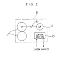
- Fig. 2 is a conceptual diagram illustrating the internal construction of each of the transportation-related units 8.
- the transportation-related units 8 each have a pair of rollers 11 for applying a transportation force to a copy sheet.
- a driving force of a motor 12 is transmitted to a shaft of one of the rollers via a clutch 81.
- the rotation speed and direction of the motor 12 are controlled by a control section 13.
- the control section 13 controls the operating conditions of the transportation-related unit 8 such as the rotation speed and direction of the motor 12 and the biasing condition of the rollers 11.
- the controlling operation is independently performed for each of the transportation-related units 8, which will be described later. More specifically, the respective transportation-related units 8 independently operate so that the copy sheet is transported from one transportation-related unit 8 to another transportation-related unit 8.
- the control sequence from the system body 10 is applied to the control section 13.
- the control section 13 interprets the control sequence to control the rotation speed and direction of the motor 12 and the state of the rollers 11.
- the control sequence applied from the system body 10 is interpreted to achieve the control of the rotating and biasing conditions of the rollers in the transportation-related unit 8.
- the transportation-related unit 8 autonomously performs a fault repairing operation. Therefore, even if the configuration of the transportation-related unit 8 is modified on a software basis or on a hardware basis, it is not necessary to change the basic functional configuration of the system body 11, thereby enabling the transportation-related unit 8 to flexibly accommodate the modification of the unit.
- the number of the sensors 9 provided in association with the transportation-related unit 8 corresponds to the number of items to be sensed.
- the sensors 9 sense whether or not a copy sheet is present at the entry and the exit of the rollers and whether or not the rollers smoothly rotate. Further, the sensors 9 sense the biasing state of the rollers 11, the amperage of the motor 12 and the like. The sensors apply signals indicative of the sensed states to the system body 10.
- a transportation belt may be employed as the actuator which is capable of performing the sheet feeding operation, the sheet transporting operation and the sheet discharging operation.
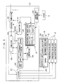
- Fig. 3 is a functional block diagram illustrating the internal constructions of the transportation-related units 8 and the system body 10.
- the system body 10 has a control data management section 20.
- the control data management section 20 writes information concerning the respective transportation-related units 8 into a data table 21 in a predetermined updating cycle on the basis of the signals from the sensors 9. More specifically, the states (STATE) of the respective transportation-related units 8 and sheet speeds (PAPER SPEED) at the respective transportation-related units 8 are written in the data table 21. Therefore, the data table 21 retains the current (latest) states of the respective transportation-related units 8.
- the data table 21 and a knowledge base to be described later correspond to the state storage means.
- the system body 10 has an evaluation section 22.
- the evaluation section 22 performs diagnostics on the current state of each of the transportation-related units 8 on the basis of the information on the transportation-related units 8 written in the data table 21. More specifically, the evaluation section 22 determines whether or not any of the transportation-related units 8 is broken, whether or not the function of any of the transportation-related units 8 is deteriorated, whether or not there is a possibility to cause a sheet jam, and whether or not a sheet jam has occurred.
- the evaluation section 22 requests a sequence formulation section 23 to formulate a control sequence for repair of the fault.
- the sequence formulation section 23 In response to the request of the formulation of the control sequence from the evaluation section 22, the sequence formulation section 23 performs a control sequence formulation operation. At this time, the sequence formulation section 23 refers to the knowledge information written in the knowledge base 24 in the system body 10.
- the knowledge base 24 functions as the knowledge storage means, and stores therein virtual models as knowledge information required for the fault repair. More specifically, the knowledge base 24 stores therein a sheet path model, a unit model, a sheet model, a transportation path model and a sensor model. Among those, the sheet path model, the sheet model, the transportation path model and the sensor model are preliminarily defined. These models will be described in greater detail later.
- the unit model is knowledge information corresponding to a difference between a state of the transportation-related unit 8 expected by the system body 10 and an actual state of the transportation-related unit 8 (e.g., deterioration of a component (rollers and the like) in the transportation-related unit 8).
- the unit model is constantly updated on the basis of data read out of the data table 21 by a state derivation section 25.
- the unit model is information indicative of a time-related change in the behavior of the transportation-related unit 8.
- the state derivation section 25 receives information on an ideal behavior of a control sequence presently executed by the transportation-related unit 8 from the simulation section 26.
- the state derivation section 25 determines a difference between the actual behavior information on the transportation-related unit 8 written in the data table 21 and the ideal behavior information, and writes information indicative of the difference as a unit model into the knowledge base 24.
- the sequence formulation section 23 formulates a control sequence by using the knowledge information including the unit model.
- the current state of the transportation-related unit 8 can be taken into consideration for the formulation of the control sequence.
- the control sequence formulated by the sequence formulation section 23 is a rough one which corresponds to a skeletal control sequence. Therefore, the control sequence is subjected to a transportation simulation which will be described later to provide an ultimate control sequence.
- the sequence formulation section 23 receives a request for the formulation of a control sequence from the outside when control specifications such as a copy speed and a transportation procedure are changed. In such a case, the sequence formulation section 23 formulates a control sequence in the same manner as described above.
- control sequence formulated by the sequence formulation section 23 is applied to the simulation section 26.
- the simulation section 26 simulates a sheet transportation operation in a virtual manner on the basis of the control sequence applied from the sequence formulation section 23. More specifically, the simulation section 26 specifies a transportation path and a sheet in a virtual manner on the basis of the sheet path model and the sheet model written in the knowledge base 24, and transports a virtual sheet along a virtual transportation path on the basis of the applied control sequence. At this time, the behavior of the virtual sheet is recognized by the simulation section 26. Further, the simulation section 26 obtains quantitative information such as PAPER SPEED and the like at the transportation-related unit 8, and reflects the quantitative information to the formulation of the control sequence. Thus, the formulation of the control sequence is completed.
- the result of the transportation simulation performed in the simulation section 26 is applied to the evaluation section 22.
- the evaluation section 22 determines on the basis of the simulation result applied from the simulation section 26 whether or not the control sequence formulated by the sequence formulation section 23 is valid.
- the evaluation section 22 If the evaluation result indicates that it is impossible to properly perform the sheet transporting operation on the basis of the formulated control sequence and to repair the fault (NO GOOD), the evaluation section 22 requests the sequence formulation section 23 again to formulate a control sequence. If it is judged that the sheet transporting operation can properly be performed on the basis of the formulated control sequence for the fault repair (GOOD), the control sequence is applied to a dividing section 27.
- the evaluation section 22 and the sequence formulation section 23 correspond to the diagnosis means and the formulation means, respectively.
- the simulation section 26 and the evaluation section 22 correspond to the judgment means, and a combination of the evaluation section 22, the sequence formulation section 23 and the simulation section 26 corresponds to the sequence generation means.
- the dividing section 27 divides the applied control sequence on a task basis, and the resulting control sequence segments are respectively applied to the corresponding transportation-related units 8. More specifically, since the control sequence is a time-series program, it is predicted that plural transportation-related units 8 are involved in the execution of the control sequence. Therefore, the control sequence segments are properly allocated to the transportation-related units 8 responsible for the execution of the control sequence.
- the system body 10 constantly monitors the overall sheet transportation system comprised of the plurality of transportation-related units 8 and, if there is a possibility to cause a transportation failure such as the slow-down of a sheet speed or a sheet jam or if such a transportation failure occurs, the system body 10 newly generates an improved control sequence for maintenance of the overall transportation system which is applied to the transportation-related units 8.
- the control section 13 of the transportation-related unit 8 has a interpretation section 28.
- the interpretation section 28 interprets the control sequence applied from the system body 10 and applies the interpreted control sequence to a controllable self-repair section 29.
- the controllable self-repair section 29 includes a sequence execution section 30.
- the sequence execution section 30 receives the control sequence applied from the interpretation section 28.
- the sequence execution section 30 controls the rotation speed and direction of the motor 12 (see Fig. 2) and the biasing state of the rollers 11 in strict conformity with the applied control sequence.
- the controllable self-repair section 29 further includes an autonomous operation section 31 which serves to perform a repairing operation on the basis of its original program.
- the autonomous operation section 31 performs diagnostics on a fault independently of the control sequence applied from the system body 10, and performs a repairing operation on the fault. More specifically, the autonomous operation section 31 performs diagnostics on a fault such as an erroneous operation due to the aging of a component or an external interference, and repairs the fault.
- the control sequence is formulated in consideration of the current states of the transportation-related units 8, and the transportaion-related units 8 operate on the basis of the control sequence. Therefore, a dynamic repairing operation can be performed for the repair of the fault. This ensures the functional maintenance for the sheet feeding and transporting system.
- the fault repair can be achieved without interrupting the operations of the copying machine.
- the validity evaluation of the repair approach by the transportation simulation enables the copying machine to perform a flexible repair operation on an unidentified fault.
- the formulation of the control sequence will hereinafter be described in greater detail. First, an explanation will be given to the knowledge information written in the knowledge base 24.
- the knowledge information is indispensable for the formulation of the control sequence.
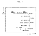
- Figs. 4 to 6 are diagrams for explaining the sheet path model.
- the sheet path model is represented as a quantitative map drawn in an x-y plane, and particular points on the map are each described by coordinates in the x-y plane and the like.
- the transportation path 7 (see Fig. 1) is represented as a line as shown in Fig. 4.
- the transportation-related units 8 disposed along the transportation path 7 are respectively represented as unit addresses on the line in accordance with the actual positions thereof.
- the sensors 9 disposed along the transportation path 7 are respectively represented as sensor addresses on the line in accordance with the actual positions thereof.
- the location and address of one sensor are shown just for illustration.
- Each line linking two adjacent unit addresses is herein referred to as "bridge".
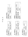
- the unit addresses, the sensor address and the bridges thus represented are described as shown in Fig. 5. More specifically, the unit addresses are each described by coordinates in the x-y plane and the status thereof. For example, “Paper Supply Unit” means that the sheet supply unit 4 is incorporated, and “Paper Feed Unit” means that the sheet transportation unit 6 is incorporated. “No Unit” means that no unit is incorporated.
- the sensor address is described by coordinates in the x-y plane and the status thereof. More specifically, the status of the sensor address indicates whether or not a sensor 9 is incorporated and, if the sensor 9 is incorporated, the status indicates the type of the incorporated sensor 9.
- the bridges are described in a manner different from the unit addresses and the sensor address. More specifically, the bridges are each described by connection points linked by the bridge, a connection form and the height of the bridge.
- the connection points each mean a unit address.
- the connection form means whether the bridge is linear or curved.
- the height means a bridge height which ensures smooth sheet transportation along the real transportation path without a sheet jam.
- the bridges are each represented by a pair of lines 40 and 41, i.e., an upper line and a lower line, connecting two adjacent unit addresses.
- the connection form of the bridge if the bridge has a curved configuration, is described by a curvature radius R of an arc drawn in the middle between the pair of curved lines 40 and 41 in concentricity therewith.
- the height of the bridge corresponds to a spacing between the pair of curved lines 40 and 41. Briefly, it is assumed that a copy sheet is transported between the pair of curved lines 40 and 41.
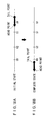
- Figs. 7 and 8 are diagrams for explaining the sensor model. As shown in Fig. 7, the sensor model is represented such that an electric digital signal is to be outputted in response to an external stimulative event with a predetermined time delay. The sensor model thus represented is described as shown in Fig. 8.
- the designation of the sensor is indexed, and the time delay and the output signal level are preliminarily defined for each of different stimulative events. More specifically, if the stimulative event is "Paper Exist” which means that a copy sheet is present, an “H” level digital signal is outputted with a time delay of X (ms). If the stimulative event is "No Paper” which means that no sheet is present, an “L” level digital signal is outputted with a time delay of XX (ms).
- Figs. 9 to 14 are diagrams for explaining the sheet model.
- the sheet model is represented by specific characteristic points on a copy sheet and an interval (or zone) between the points.
- the characteristic points on the sheet include a head point corresponding to a leading edge of the sheet, a tail point corresponding to a trailing edge of the sheet, and unit points at which transportation-related units 8 serving to apply a dynamic force to the sheet for the sheet transportation are located.
- a driving mode the rollers 11 (see Fig. 2) in the transportation-related unit 8 are biased against each other with a predetermined nip pressure to be ready to apply a transportation force to the copy sheet.
- the free mode conversely, the biasing state of the rollers 11 is eliminated, so that the rollers cannot apply a transportation force to the copy sheet for the transportation of the sheet.
- the interval is one factor representing the state of the copy sheet, and defines a zone between the head point or the tail point and a unit point in the driving mode in which a transportation force can be applied to the copy sheet.
- a unit point in the free mode is not herein taken into consideration. This is because the unit point in the free mode does not apply a transportation force to the copy sheet so that the state of the copy sheet is not influenced thereby.
- the head point, the tail point and the unit points thus represented are described as shown in Figs. 10A and 10B. More specifically, the head point and the tail point are each described by the designation of the point and a real speed corresponding to the speed of the copy sheet at the point as shown in Fig. 10A.
- the real speed is calculated from the rotational speed of the rollers 11 which is sensed, for example, by an encoder with the copy sheet brought in contact with the rollers 11 (see Fig. 2).
- the unit points are each described by the designation and mode of the point, the type of a transportation-related unit corresponding to the unit point, and a real speed at the unit point, as shown in Fig. 10B.
- the unit point influences the state of the copy sheet.
- the influence may result in the following three states (see Fig. 11):
- the influence to be exerted on the sheet is changed by changing the mode of the unit point and, if the unit point is put in the driving mode, by changing the target speed.
- the influence is reflected to the interval. More specifically, since the interval is defined by two adjacent points, the state of the interval is changed by the influence exerted on the sheet by these two points.
- an upper point and a lower point respectively located upstream and downstream of the copy sheet in a sheet transportation direction are specified as shown in Fig. 12, and how the interval is influenced by the modes of these points and the target speeds at the points are also described.
- the state of the interval is represented on the basis of three standard representations, i.e., "N", “TEAR” and "BM”, which mean a normal state, a tensile limit and a flexure limit, respectively.
- N an interval state between "N” and “BM” is a slacked state, which is represented as “increase”.
- An interval state between "N” and “TEAR” is a tensed state, which is represented as "decrease”.
- Fig. 14 is a diagram illustrating the relationships between the modes of the points, the target speeds at the points and the interval states. First, an explanation will be given to terms used in Fig. 14.
- TVlower and TVupper are a target speed at the lower point and a target speed at the upper point, respectively.
- RVlower and RVupper are a real speed at the lower point and a real speed at the upper point, respectively.
- IState is the interval state. More specifically, "[N, TEAR]” indicates that the interval is in a state between “N” and “TEAR", i.e., in a tensed state “decrease”. "[N, BM]” indicates that the interval is in a state between “N” and “BM”, i.e., in a slacked state “increase”. “[N, TEAR], N” indicates that the interval is in a state between "N” and “TEAR” including "N”, and “[N, BM], N” indicates that the interval is in a state between "N” and “BM” including “N”.
- the sequence formulation section 23 formulates a control sequence by utilizing the knowledge information stored in the knowledge base 24 in response to the request from the evaluation section 22 or from the outside, as described above. 4-2. Models to be Used for Formulation of Control Sequence
- the sequence formulation section 23 simplifies the sheet path model and the sheet model written in the knowledge base 24 in the following manner for representation thereof. More specifically, the transportation path is represented as a line in a virtual manner as shown in Fig. 15A. At this time, the lengths between the respective unit addresses along the virtual transportation path are described as shown in Fig. 15B. The sheet model is overlaid on the virtual transportation path.
- the information on the interval is described in slots of a table as shown in Fig. 15C. More specifically, the information on the interval includes a designation for identifying the interval, the point names of the upper point and the lower point and the state of the interval.
- the interval state corresponds to a concept which will be described later.
- the information on the sheet model includes the designation of a sheet corresponding to the size of the sheet, the point names of the head point and the tail point of the sheet, and the friction coefficient and the length of the sheet. 4-3. Conditions to be Satisfied by Formulated Control Sequence
- the sequence formulation section 23 uses the virtual transportation path and the virtual sheet represented in the aforesaid manner to determine conditions to be satisfied for the formulation of the control sequence. More specifically, qualitative specifications are first determined.
- the qualitative specifications define indispensable conditions required to be satisfied for the formation of the control sequence, and are represented by an initial state of the sheet and a complete state of the sheet after the completion of the sheet transportation.
- the complete state of the sheet is properly defined.
- the complete state to be determined may be such a state that the sheet is located upstream of the initial position of the sheet after the sheet transportation. If there is a possibility to cause a sheet jam, it may be preferred to transport the sheet in a direction opposite to a usual transportation direction for easy repair.
- the initial state of the sheet is determined in the following manner.
- the position of the copy sheet in the real transportation path 7 (see Fig. 1) is determined which corresponds to a position in the virtual transportation path where the sheet model is to be located, with reference to the unit model stored in the knowledge base 24, and the initial state is determined such that the sheet model is located at this position.
- the unit model retains information concerning the current state of the transportation-related unit 8 written by the state derivation section 25, the current position of the copy sheet can be determined by referring to the information.
- the position of the copy sheet is determined which corresponds to a position where a copy sheet is in the sheet feeding cassette, and the initial state is determined such that the sheet model is located at this position.
- the initial state and the complete state are represented by positional relationships between the leading edge of the virtual sheet and the respective points in the virtual transportation path. More specifically, where the initial state is such as shown in Fig. 16A, the initial state is described as follows:
- an additional condition is employed for the transportation of the virtual sheet. More specifically, the condition is such that at least one unit point in the driving mode is present in the sheet model.
- the sequence formulation section 23 determines quantitative specifications necessary for satisfying the qualitative specifications thus determined.
- the quantitative specifications are less strict conditions which are not necessarily satisfied when the control sequence is formulated.
- the quantitative specifications include a copy speed and the like.
- Conditions to be satisfied by the sequence formulation section 23 include a predetermined concept in addition to the qualitative specifications and the quantitative specifications.
- the concept represents a state of a copy sheet which should be satisfied for execution of the control sequence. More specifically, the concept determines whether the copy sheet is to be transported in a normal state, in a tensed state or in a slacked state.
- the state of the copy sheet is described in the same manner as the state of the interval described in the aforesaid table, in which such expressions as "[N, TEAR], "[N, BM], N” and the like are used.
- the concept thus determined is described in slots of a table as shown in Fig. 15C.
- the sequence formulation section 23 formulates the control sequence so as to satisfy the qualitative specifications, the quantitative specifications and the concept.
- a sheet path model represented by three unit addresses and one sensor address as shown in Fig. 17A is employed for simplification of explanation of the preparation of the zone shift sequence.
- the length of a virtual sheet is determined, and the lengths between the respective addresses are described as shown in Fig. 17B.
- the qualitative specifications are determined as shown in Figs. 18A and 18B. More specifically, the qualitative specifications are described as follows:
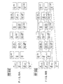
- the sequence formulation section 23 lists up all possible combinations (hereinafter referred to as "frames") of zones where the head point and the tail points are possibly present, as shown in Fig. 19A.
- the upper line and the lower line in each frame correspond to the head point and the tail point, respectively.
- the initial state and the complete state are incorporated into the network as shown in Figs. 20A and 20B to satisfy the qualitative specifications. More specifically, a frame having the same state as the initial state or a frame which possibly comes next to the frame corresponding to the initial state and defines the zones where the head point and the tail point are to be located next is selected, and the selected frame is related with the initial state. In the example shown in Fig. 20A, the frame corresponding to the initial state is selected. Then, a frame having the same state as the complete state or a frame which corresponds to a state preceding the complete state is selected, and the selected frame is related with the complete state. In the example shown in Fig. 20A, the frame corresponding to the state preceding the complete state is selected.
- a combination of frames which provides the shortest way for the shift from the initial state to the complete state is searched for in the network shown in Fig. 20A.
- a combination of the frames "Initial State -> a -> b -> ... -> 1 -> m -> Complete State" linked by bold lines as shown in Fig. 20B is selected, which possibly provides the shortest way.
- the combination of the frames is referred to as "zone shift sequence”.
- the zone shift sequence thus selected is represented as shown in Fig. 21 on the basis of time-related factors as well as the virtual transportation path and the virtual sheet.
- Shift conditions required for shift from one frame to the next frame with time are determined for the zone shift sequence thus selected. More specifically, the shift conditions include a target speed to be determined when the mode of a unit point is specified or the unit point is put in the driving mode. The shift conditions thus determined are arranged on a time-series basis to form the control sequence.
- the sheet path model shown in Fig. 22A is represented only by three unit addresses U1, U2 and U3. Further, the sheet model has a length of 150 (mm). The lengths between the unit addresses U1 and U2 and between the unit addresses U2 and U3 are described as shown in Fig. 22B.
- the unit point Ul is in the free mode in the initial state, and the unit points U1 and U2 are in the driving mode in the complete state.
- the frame A is shifted to a frame A' in which the unit point U1 in the driving mode is present between the head point and the tail point and two intervals 1 and 2 are present as shown in Fig. 25B.
- the frame A' is shifted to the frame B for the shift from the frame A to the frame B. More specifically, the head point in the frame A' is allowed to correspond to a unit point U2 as shown in Fig. 25C. This is apparently achieved by making the real speed of the head point positive in the frame A'.
- the shift from the frame B to a frame C will be considered.
- the shift from the frame B to the frame C is achieved by moving the head point in the frame B to a position between a unit point U2 and a unit point U3.
- the sheet model is represented as shown in Fig. 25D.
- the real speed RVH of the head point is made positive in the frame B.
- the target speed TVU2 at the unit point U2 is made positive to make the real speed RVH of the head point positive.
- an additional condition should be specified.
- the concept for the formulation of the control sequence is "Normal" as described above. This means that the state of the interval b corresponding to the zone between the unit points U1 and U2 should be kept “Normal”.
- the target speed TVU1 at the unit point U1 for the shift from the frame A to the frame B is already set to X (X > 0). Therefore, the target speed TVU2 of the unit point U2 should be specified such that the target speed TVU2 is always equal to the target speed TVU1 at the unit point U1.
- the sequence of the shift conditions thus prepared serves as the control sequence.
- system body 10 is provided within the copying machine body in the aforesaid embodiment, the system body 10 may be provided as a discrete device outside the copying machine body. With such an arrangement, the construction of the copying machine body can be simplified.
- the present invention is applied to the copying machine, but may be applied to any other apparatuses such as a printer and a facsimile machine which have a sheet feeding and transporting system.
Landscapes
- Physics & Mathematics (AREA)
- General Physics & Mathematics (AREA)
- Controlling Sheets Or Webs (AREA)
- Control Or Security For Electrophotography (AREA)
- Paper Feeding For Electrophotography (AREA)
Applications Claiming Priority (2)
| Application Number | Priority Date | Filing Date | Title |
|---|---|---|---|
| JP125847/96 | 1996-05-21 | ||
| JP8125847A JPH09311599A (ja) | 1996-05-21 | 1996-05-21 | 自己修復機能を備えた用紙搬送装置 |
Publications (1)
| Publication Number | Publication Date |
|---|---|
| EP0809155A1 true EP0809155A1 (de) | 1997-11-26 |
Family
ID=14920421
Family Applications (1)
| Application Number | Title | Priority Date | Filing Date |
|---|---|---|---|
| EP97303422A Withdrawn EP0809155A1 (de) | 1996-05-21 | 1997-05-20 | Blatttransportvorrichtung mit Selbstreparaturfunktion |
Country Status (4)
| Country | Link |
|---|---|
| EP (1) | EP0809155A1 (de) |
| JP (1) | JPH09311599A (de) |
| KR (1) | KR970076133A (de) |
| TW (1) | TW337558B (de) |
Families Citing this family (1)
| Publication number | Priority date | Publication date | Assignee | Title |
|---|---|---|---|---|
| JP2006279177A (ja) * | 2005-03-28 | 2006-10-12 | Fuji Xerox Co Ltd | 画像形成装置およびその制御システム |
Citations (7)
| Publication number | Priority date | Publication date | Assignee | Title |
|---|---|---|---|---|
| EP0259144A2 (de) * | 1986-09-02 | 1988-03-09 | Xerox Corporation | Vervielfältigungsgerät mit Fehlerermittlungssystem |
| US5018718A (en) * | 1988-12-28 | 1991-05-28 | Hitachi, Ltd. | Sheet registration method and apparatus for calculation of delay time and sheet feed control thereby |
| US5053815A (en) * | 1990-04-09 | 1991-10-01 | Eastman Kodak Company | Reproduction apparatus having real time statistical process control |
| EP0476681A2 (de) * | 1990-09-21 | 1992-03-25 | Mita Industrial Co. Ltd. | Selbstdiagnose- und Reparatursystem für Bilderzeugungsgerät |
| JPH04130331A (ja) * | 1990-09-21 | 1992-05-01 | Mita Ind Co Ltd | 画像形成装置のための自己診断および自己修復システム |
| EP0583928A2 (de) * | 1992-08-17 | 1994-02-23 | Xerox Corporation | Geschwindigkeitsprofilanalysegerät und -methode für den Papierweg |
| US5502544A (en) * | 1994-09-15 | 1996-03-26 | Xerox Corporation | Parameter based digital servo controller |
-
1996
- 1996-05-21 JP JP8125847A patent/JPH09311599A/ja active Pending
-
1997
- 1997-05-19 TW TW086106642A patent/TW337558B/zh active
- 1997-05-20 EP EP97303422A patent/EP0809155A1/de not_active Withdrawn
- 1997-05-20 KR KR1019970019479A patent/KR970076133A/ko not_active Withdrawn
Patent Citations (7)
| Publication number | Priority date | Publication date | Assignee | Title |
|---|---|---|---|---|
| EP0259144A2 (de) * | 1986-09-02 | 1988-03-09 | Xerox Corporation | Vervielfältigungsgerät mit Fehlerermittlungssystem |
| US5018718A (en) * | 1988-12-28 | 1991-05-28 | Hitachi, Ltd. | Sheet registration method and apparatus for calculation of delay time and sheet feed control thereby |
| US5053815A (en) * | 1990-04-09 | 1991-10-01 | Eastman Kodak Company | Reproduction apparatus having real time statistical process control |
| EP0476681A2 (de) * | 1990-09-21 | 1992-03-25 | Mita Industrial Co. Ltd. | Selbstdiagnose- und Reparatursystem für Bilderzeugungsgerät |
| JPH04130331A (ja) * | 1990-09-21 | 1992-05-01 | Mita Ind Co Ltd | 画像形成装置のための自己診断および自己修復システム |
| EP0583928A2 (de) * | 1992-08-17 | 1994-02-23 | Xerox Corporation | Geschwindigkeitsprofilanalysegerät und -methode für den Papierweg |
| US5502544A (en) * | 1994-09-15 | 1996-03-26 | Xerox Corporation | Parameter based digital servo controller |
Non-Patent Citations (1)
| Title |
|---|
| PATENT ABSTRACTS OF JAPAN vol. 016, no. 396 (P - 1407) 21 August 1992 (1992-08-21) * |
Also Published As
| Publication number | Publication date |
|---|---|
| TW337558B (en) | 1998-08-01 |
| JPH09311599A (ja) | 1997-12-02 |
| KR970076133A (ko) | 1997-12-10 |
Similar Documents
| Publication | Publication Date | Title |
|---|---|---|
| US5838596A (en) | Simulation system for control sequence for sheet transportation | |
| US5138377A (en) | Internal expert system to aid in servicing | |
| EP0259144B1 (de) | Vervielfältigungsgerät mit Fehlerermittlungssystem | |
| US8031358B2 (en) | Image forming system including a plurality of image forming apparatuses | |
| US20040022561A1 (en) | Image forming apparatus and method | |
| EP0476681B1 (de) | Selbstdiagnose- und Reparatursystem für Bilderzeugungsgerät | |
| JPS58136473A (ja) | プリント装置 | |
| US6643474B2 (en) | Abnormality displaying apparatus for use in image forming apparatus | |
| US5999757A (en) | Sheet transportation device | |
| JP2706399B2 (ja) | 画像形成装置のための制御装置 | |
| EP0809155A1 (de) | Blatttransportvorrichtung mit Selbstreparaturfunktion | |
| JPH0635264A (ja) | 画像形成方法および装置 | |
| US5844819A (en) | Method and apparatus for aiding design of mechanism | |
| EP0593018B1 (de) | Bilderzeugungsgerät mit Selbstreparaturfunktion | |
| JP2008097281A (ja) | プログラム生成システム、シーケンスプログラム、シーケンス制御方法、およびシーケンサ装置 | |
| JP2793424B2 (ja) | 自己診断可能な画像形成装置 | |
| Umeda et al. | A design methodology for a self-maintenance machine | |
| JP2793419B2 (ja) | 自己診断可能な画像形成装置 | |
| JP2793422B2 (ja) | 自己診断可能な画像形成装置 | |
| JP3127931B2 (ja) | 画像記録装置の診断方法及び予防方法並びにこれらのシステム | |
| JPH10186770A (ja) | 多色画像形成装置 | |
| JP2793421B2 (ja) | 自己診断可能な画像形成装置 | |
| JP2793423B2 (ja) | 自己診断可能な画像形成装置 | |
| JP2793420B2 (ja) | 自己診断可能な画像形成装置 | |
| JPH04366972A (ja) | 画像作成装置 |
Legal Events
| Date | Code | Title | Description |
|---|---|---|---|
| PUAI | Public reference made under article 153(3) epc to a published international application that has entered the european phase |
Free format text: ORIGINAL CODE: 0009012 |
|
| AK | Designated contracting states |
Kind code of ref document: A1 Designated state(s): DE FR GB IT |
|
| 17P | Request for examination filed |
Effective date: 19980128 |
|
| STAA | Information on the status of an ep patent application or granted ep patent |
Free format text: STATUS: THE APPLICATION HAS BEEN WITHDRAWN |
|
| 18W | Application withdrawn |
Withdrawal date: 19981202 |