EP0809134A1 - Dispositif d'éclairage pour une imprimante photographique - Google Patents
Dispositif d'éclairage pour une imprimante photographique Download PDFInfo
- Publication number
- EP0809134A1 EP0809134A1 EP96810324A EP96810324A EP0809134A1 EP 0809134 A1 EP0809134 A1 EP 0809134A1 EP 96810324 A EP96810324 A EP 96810324A EP 96810324 A EP96810324 A EP 96810324A EP 0809134 A1 EP0809134 A1 EP 0809134A1
- Authority
- EP
- European Patent Office
- Prior art keywords
- light
- copying
- deflecting mirror
- mixer
- green
- Prior art date
- Legal status (The legal status is an assumption and is not a legal conclusion. Google has not performed a legal analysis and makes no representation as to the accuracy of the status listed.)
- Withdrawn
Links
- 238000005286 illumination Methods 0.000 claims abstract description 20
- 239000003086 colorant Substances 0.000 claims description 21
- 239000000463 material Substances 0.000 claims description 17
- 238000002310 reflectometry Methods 0.000 claims description 17
- 230000005540 biological transmission Effects 0.000 claims description 10
- 238000004040 coloring Methods 0.000 claims description 5
- 238000003384 imaging method Methods 0.000 claims description 5
- 230000005855 radiation Effects 0.000 description 15
- 230000003595 spectral effect Effects 0.000 description 15
- 230000008901 benefit Effects 0.000 description 11
- 238000000034 method Methods 0.000 description 11
- 230000004224 protection Effects 0.000 description 10
- 230000035945 sensitivity Effects 0.000 description 8
- 229910052736 halogen Inorganic materials 0.000 description 6
- 150000002367 halogens Chemical class 0.000 description 6
- 238000010521 absorption reaction Methods 0.000 description 5
- 238000010586 diagram Methods 0.000 description 5
- 230000000295 complement effect Effects 0.000 description 4
- 238000004519 manufacturing process Methods 0.000 description 4
- 230000003287 optical effect Effects 0.000 description 4
- 239000000654 additive Substances 0.000 description 3
- 230000000996 additive effect Effects 0.000 description 3
- 230000008569 process Effects 0.000 description 3
- 230000009467 reduction Effects 0.000 description 3
- 230000008859 change Effects 0.000 description 2
- 230000000694 effects Effects 0.000 description 2
- 230000005284 excitation Effects 0.000 description 2
- 230000006750 UV protection Effects 0.000 description 1
- 230000002411 adverse Effects 0.000 description 1
- 230000006378 damage Effects 0.000 description 1
- 230000001419 dependent effect Effects 0.000 description 1
- 238000005516 engineering process Methods 0.000 description 1
- 238000005259 measurement Methods 0.000 description 1
- 230000003071 parasitic effect Effects 0.000 description 1
- 230000035699 permeability Effects 0.000 description 1
- 230000001681 protective effect Effects 0.000 description 1
- 239000000758 substrate Substances 0.000 description 1
- 230000003685 thermal hair damage Effects 0.000 description 1
- 238000007740 vapor deposition Methods 0.000 description 1
- 230000003313 weakening effect Effects 0.000 description 1
Images



Classifications
-
- G—PHYSICS
- G03—PHOTOGRAPHY; CINEMATOGRAPHY; ANALOGOUS TECHNIQUES USING WAVES OTHER THAN OPTICAL WAVES; ELECTROGRAPHY; HOLOGRAPHY
- G03B—APPARATUS OR ARRANGEMENTS FOR TAKING PHOTOGRAPHS OR FOR PROJECTING OR VIEWING THEM; APPARATUS OR ARRANGEMENTS EMPLOYING ANALOGOUS TECHNIQUES USING WAVES OTHER THAN OPTICAL WAVES; ACCESSORIES THEREFOR
- G03B27/00—Photographic printing apparatus
- G03B27/32—Projection printing apparatus, e.g. enlarger, copying camera
- G03B27/52—Details
- G03B27/70—Reflectors in printing beam
-
- G—PHYSICS
- G03—PHOTOGRAPHY; CINEMATOGRAPHY; ANALOGOUS TECHNIQUES USING WAVES OTHER THAN OPTICAL WAVES; ELECTROGRAPHY; HOLOGRAPHY
- G03B—APPARATUS OR ARRANGEMENTS FOR TAKING PHOTOGRAPHS OR FOR PROJECTING OR VIEWING THEM; APPARATUS OR ARRANGEMENTS EMPLOYING ANALOGOUS TECHNIQUES USING WAVES OTHER THAN OPTICAL WAVES; ACCESSORIES THEREFOR
- G03B27/00—Photographic printing apparatus
- G03B27/32—Projection printing apparatus, e.g. enlarger, copying camera
- G03B27/52—Details
- G03B27/54—Lamp housings; Illuminating means
- G03B27/545—Lamp housings; Illuminating means for enlargers
Definitions
- the invention relates to an illumination device for a photographic copier according to the preamble of claim 1.
- copies of master copies are usually made in such a way that the master copies, for example the image fields of a negative film strip, are first measured in terms of their density and color, and the required quantities of copy light in the three primary colors red, blue and green are determined therefrom.
- the image fields are then exposed on photographic copying material, for example photographic paper, by means of the determined amounts of copying light.
- the image field to be copied is imaged on the photographic copying material by means of an illumination device and an imaging optics. Numerous methods and devices are known from the prior art for realizing the amounts of copying light required in the three primary colors.
- One possibility is e.g. B. to use a light source for emitting the copying light, which emits "white” light, for example a halogen lamp, and to color this white light according to the desired amount of copying light in the three primary colors.
- a light source for emitting the copying light which emits "white” light, for example a halogen lamp, and to color this white light according to the desired amount of copying light in the three primary colors.
- e.g. B. provided optical color filters in the complementary colors yellow, magenta and cyan, which can be introduced more or less deep in the exposure beam path. In this way, the three color components (red, green, blue) in the copying light can each be weakened so that the copying light is given the desired color.
- Another possibility of exposure is to also use a white light source and to completely introduce red, blue and green filters sequentially into the exposure beam path, so that the exposure takes place in the three primary colors in succession.
- the duration of the exposure which in addition to the copying light intensity also determines the amount of copying light, is usually controlled by a shutter in the illuminating beam path between the light source and the copying material.
- the closure device in the In the closed state, prevents the copying material from being acted upon by the copying light; if it is open, however, the copying light reaches the copying material.
- a reproduction of the copy original that is as true to color as possible requires, among other things, that the special characteristics of the photo paper are taken into account in the coloring of the copy light or in the exposure.
- the three layers of color (yellow, magenta, cyan) on photo paper react differently to the light that is applied to them, depending on the wavelength.
- the spectral sensitivity of a photographic paper as a function of the wavelength has a relatively complicated course.
- the main maxima at the wavelengths of the three primary colors are usually quite broad.
- the spectral paper sensitivities for the three primary colors show a not negligible overlap.
- the spectral sensitivities often have secondary maxima.
- DE-A-36 15 284 proposes the use of an additional filter device which has three spectrally narrow-band permeability regions, each in a basic color.
- a device which has a white one Light source, an imaging optics and at least three color filters (cyan, magenta, yellow) which can be pivoted in selectively by means of a device.
- a filter combination is provided which only allows light to pass within narrow spectral ranges. The light emitted by the white light source is first colored by the three color filters in the complementary colors to the desired red-green-blue composition.
- the copying light then passes through the additional filter device, which has the three spectrally narrowband transmission ranges in the colors red, green and blue.
- its spectral composition essentially has only three narrowband maxima in the basic colors red, green and blue.
- the copying light acts on the negative and is then guided through a lens onto the copying material.
- the spectral narrow-band exposure ensures that the special shape of the spectral sensitivity curves of the copying material is negligible during the exposure.
- the overlap regions no longer exert any significant disruptive influence because the spectral regions in which the sensitivities of the color layers of the photo paper overlap are largely masked out from the copying light. This has the additional advantage that richer colors can be produced on the copy.
- Halogen lamps are among the most frequently used light sources in generic lighting devices today. They have the undesirable property that a large part of the radiation they emit occurs as heat, ie as radiation in the infrared range. A high heat load can, however, lead to considerable damage, for example to the various filters or the copy templates. Likewise, high levels of heat can have adverse consequences for the copying process because the operating conditions, e.g. B. the temperature can change in a non-controllable manner.
- heat protection filters are often arranged in the illumination beam path, which have the property of essentially only transmitting radiation with wavelengths below the infrared range.
- the protective filters In order to achieve efficient thermal protection, however, it is necessary that the protective filters have to block far into the infrared range.
- Such Thermal protection filters are therefore relatively complex to manufacture and accordingly expensive.
- Another possibility of heat protection is the use of so-called cold light mirrors. These are essentially transparent to infrared radiation, but reflect the visible light.
- the invention has for its object to provide an illumination device for a photographic copier, which is as inexpensive as possible and still allows both spectrally narrow band exposure and efficient dissipation of the heat radiation from the light source.
- the lighting device for a photographic copier that achieves these and other tasks is characterized by the features of the independent patent claim.
- the lighting device thus comprises a deflecting mirror which is essentially transparent in the infrared wavelength range and which has a reflectivity in the visible wavelength range which has three spectrally narrow-band maxima which are in the wavelength ranges of red, green and blue light.
- This measure has the advantage that several functions, which have hitherto usually been carried out by several components, that is to say physically separate units, are carried out in the lighting device according to the invention by only one structural unit, namely the deflecting mirror.
- the deflecting mirror serves, on the one hand, to supply the copying light emitted by the light source to the light mixer, and on the other hand, due to its transparency in the infrared wavelength range, it ensures efficient dissipation of the heat radiation of the light source from the illumination beam path.
- due to its selective, spectrally narrow-band reflectivity in the visible wavelength range it limits the copying light to three narrow-band wavelength ranges.
- the lighting device according to the invention manages with fewer components than comparable, known devices. This reduces the effort, while an advantageous spectrally narrow-band exposure and an efficient dissipation of the heat radiation is still guaranteed.
- the deflecting mirror so that it can be tilted between two positions, wherein in the first position it deflects the copying light coming from the light source into the light mixer, and in the second position it deflects the copying light away from the light mixer.
- the deflecting mirror thus additionally takes on the function of a closure device, which results in a further reduction in the components required.
- a first embodiment of the lighting device according to the invention which is designated overall by the reference numeral 1, is outlined.
- the illustration is limited to the parts essential for understanding the invention. For reasons of better clarity, well-known details, such as holding and actuating devices, are not shown.
- the lighting device 1 for a photographic copier comprises a light source 2 for emitting copying light, a light mixer 4 and means for supplying the copying light emitted by the light source 2 to the light mixer 4.
- these means comprise a deflection mirror 3 which is essentially transparent in the infrared wavelength range and which has a reflectivity in the visible wavelength range which has three spectrally narrow-band maxima which lie in the wavelength ranges of red, green and blue light.
- the three maxima of the reflectivity of the deflecting mirror 3 advantageously each have a width of less than 100 nm.
- the maxima in the wavelength ranges of green and blue light each preferably have a width of less than 50 nm.
- the term width means the full width at half maximum.
- the deflecting mirror 3 is preferably designed in such a way that its function is based on the principle of interference and it has a negligibly low absorption capacity. This has the advantage that its heat absorption is extremely low because most of the radiation portion of the light that is not reflecting it is transmitted, not but is absorbed. In this way, thermal damage to the deflecting mirror 4 can be avoided efficiently.
- FIG. 1 In addition to the lighting device 1, further components are shown in FIG. 1, which are usually provided in photographic copiers. Since these components are sufficiently well known per se, they require no further explanation.
- a film stage 6 in the illuminating beam path which is symbolically represented by an optical axis O, for guiding and supporting a copy template (not shown).
- a shutter 7 In the further illumination beam path, a shutter 7 is arranged and an imaging optics 8, with which the copy original to be exposed is imaged on copy material, for the guidance and support of which a copy stage 9 is provided.
- the exemplary embodiment of the lighting device according to the invention shown in FIG. 1 is designed for a subtractive exposure method.
- a filter arrangement 5 for coloring the copying light is provided between the deflecting mirror 3 and the light mixer 4 in the illuminating beam path, said filter arrangement containing transmission filters 51, 52, 53 in the colors magenta, cyan and yellow.
- the transmission filters 51, 52, 53 are preferably interference filters and can each be designed in one piece or in the form of two filter halves.
- the three transmission filters 51, 52, 53 can each be moved more or less deeply into the illumination beam path independently of one another, so that a more or less large proportion of the cross section of the copying light beam is detected by them .
- the color components of the copying light in the three primary colors red, green and blue, essentially independently of one another, can be weakened to the desired values in order to achieve the required coloring of the copying light.
- the light source 2 comprises an ellipsoidal reflector 22 and a halogen lamp 21 which is arranged in the ellipsoidal reflector 22 such that the filament is essentially in one of the focal points of the ellipsoidal reflector 22 on the optical axis O.
- the light mixer 4 is designed as a light shaft which has a diffusing screen 41 on the light input side.
- the light mixer 4 is used for intimate Mixing of the copying light and for homogenizing the illuminance over the surface of the copy template.
- the deflecting mirror 3 is arranged in the illumination beam path between the light source 2 and the light shaft 4 in such a way that its reflecting surface is inclined at an angle of approximately 45 ° with respect to the optical axis.
- the distances between the light source 2 and the deflecting mirror 3 and between the deflecting mirror 3 and the light mixer 4 are dimensioned such that the filament of the halogen lamp 21 is imaged in the region of the lens 41 of the light mixer 4.
- the functioning of this exemplary embodiment of the lighting device according to the invention is as follows:
- the essentially white light emitted by the halogen lamp 21 impinges on the deflecting mirror 3. If, in a simplistic manner, one assumes that the light from the halogen lamp 21 is ideally white, this means that at least in the visible wavelength range the spectral composition of the light is such that all wavelengths are represented in the light with the same frequency.
- the intensity as a function of the wavelength is constant. Since the deflecting mirror 3 is transparent in the infrared wavelength range, it allows the spectral portion of the light which impinges it in the form of heat radiation to pass through essentially unimpeded.
- a heat absorption device (not shown in FIG. 1) can be provided, for example, in the direction of illumination behind the deflecting mirror 3 in order to receive the heat radiation which transmits the deflecting mirror 3.
- the deflecting mirror 3 only selectively reflects the proportion of light with wavelengths in the visible range, depending on the wavelength.
- the reflectivity of the deflection mirror 3 has three spectrally narrow-band maxima in the visible wavelength range (see FIG. 2), which lie in the wavelength ranges of red, green and blue light.
- the portions of the light whose wavelengths lie between the red and the green area or between the green and the blue area can also pass the deflection mirror essentially unhindered, ie are removed from the illumination beam path.
- the proportions of light whose wavelengths are in the region of the maxima of the reflectivity of the deflection mirror 3 are reflected by the deflection mirror in the direction of the filter arrangement 5 or the diffusing screen 41 of the light mixer 4.
- the spectral Composition of the copying light which acts on the filter arrangement 5 such that essentially only wavelengths from three spectrally narrow-band regions are represented in the copying light. In terms of color, the copying light therefore only contains three spectrally narrow-band components in the colors red, blue and green.
- the filter arrangement 5 then, as already described above, colors the copying light by weakening the three color components in the primary colors, red, blue, green, to the desired intensity in each case by the transmission filters 51, 52, 53 which are inserted deeply into the illumination beam path.
- This desired intensity can be calculated, for example, taking into account the results of a previous measurement of the master copy.
- the colored copying light then passes through the lens 41 into the light mixer 4, where it is mixed intimately.
- the lighting device 1 is integrated in a conventional photographic copying machine, as is symbolically indicated in FIG. 1, the colored copying light penetrates the copying template placed on the film stage 6 after leaving the light mixer 4. If the closure device 7 is now opened, the copying light exposes the copying material, for example photo paper, which is placed on the copying stage 9. The duration of the exposure can be controlled by opening or closing the closure device 7. When the closure device 7 is open, the imaging optics 8 images the master copy onto the copy material.
- the deflecting mirror 3, which is transparent in the infrared wavelength range, in the lighting device according to the invention has the advantage in comparison with the infrared cut-off filters frequently used in known lighting devices that it is easier and cheaper to produce.
- Common infrared cut filters that are operated in transmission are transparent for wavelengths below the infrared range and reflect the infrared radiation. In order to achieve effective heat protection through such filters, it is necessary that these filters block far into the infrared range. Such heat protection filters are therefore usually quite complicated and expensive to manufacture.
- the lighting device has the advantage that several functions, which in known devices of the generic type usually have a plurality physically separate units are distributed, can be exercised by only one structural unit, namely the deflecting mirror 3.
- the deflecting mirror 3 serves, on the one hand, to supply the copying light emitted by the light source 2 to the light mixer, and on the other hand, due to its transparency in the infrared wavelength range, it ensures efficient dissipation of the heat radiation of the light source 2 from the illumination beam path, and moreover it limits it by its selective nature , spectrally narrow-band reflectivity in the visible wavelength range the copying light on three narrow-band wavelength ranges.
- the excitation of the overlap areas of the spectral sensitivity curves of the copying material is effectively suppressed without the need for additional filter devices.
- thermal protection is implemented either by means of infrared cut filters or by cold light mirrors - these are mirrors which are transparent in the infrared range and have a spectrally substantially constant reflectivity in the visible range.
- additional filter devices are then necessary, which are normally operated in transmission and have spectrally narrow transmission ranges.
- the lighting device according to the invention thus has the advantage of being less complex and nevertheless enabling the advantageous spectrally narrowband exposure and efficient heat protection.
- the deflection mirror 3 is essentially transparent even in the ultraviolet (UV) wavelength range.
- the deflecting mirror 3 then also takes on the function of efficient UV protection. This has the advantage that there is no need for additional UV cut-off filters, which further reduces the outlay on equipment.
- the exemplary embodiment shown in FIG. 1 can also contain means for measuring and analyzing the colored copying light.
- a partially transparent mirror can be arranged in the illumination beam path behind the light mixer, with which part of the colored copying light is fed to a measuring device with which it can be determined whether the colored copying light has the desired color composition.
- the lighting device according to the invention can also be designed for an additive exposure method.
- the filter arrangement 5 contains at least three color filters in the basic colors green, blue and red, which can be introduced sequentially into the illumination beam path.
- a color filter wheel known per se can be provided with a filter assembly which comprises at least filters in the three primary colors.
- Such filter wheels can typically be driven by a motor.
- the filter wheel swings the three color filters in red, green and blue one after the other into the beam path for the duration of the calculated exposure time.
- the lighting device according to the invention can also be used to carry out additive exposure methods with the advantages of spectrally narrow-band exposure.
- the deflection mirror 3 ensures that the copying light which acts on the filter arrangement 5 is limited to three spectrally narrow-band wavelength ranges.
- FIG. 2 shows a diagram in which the reflectivity of the deflection mirror 3 is shown as a function of the wavelength with an exemplary character.
- the wavelength of the light is plotted in the unit nanometer on the axis labeled ⁇ , and the intensity of the light reflected by the mirror is plotted on the axis labeled R.
- This intensity is normalized to the intensity of the light impinging on the deflecting mirror 3, ie an intensity of the reflected light of 1 means that the incident light is completely, ie 100% reflected, an intensity of the reflected light of 0 means that the incident light is not reflected at all.
- the diagram clearly shows that the reflectivity of the deflection mirror 3 has three spectrally narrow-band maxima, which lie in the wavelength ranges of red, green and blue light. Consequently, the light reflected by the deflecting mirror 3 essentially only contains wavelengths which belong to the three narrow-band-limited areas. Light with wavelengths between the red and green areas or between the green and blue areas is essentially not reflected by the deflecting mirror, so that it is removed from the illuminating beam path.
- FIG. 3 corresponds to that shown in FIG. 2, but a larger wavelength range is shown in FIG. 3.
- This diagram demonstrates the heat protection function of the deflecting mirror 3. It can be clearly seen that the deflecting mirror 3 for light with wavelengths above the visible spectral range, that is, for. B. for infrared radiation, is substantially transparent.
- the production of the deflecting mirror 3 can by means of methods known per se, such as the application, for. B. by vapor deposition of several superimposed layers on a substrate serving as a carrier.
- the layers lying one above the other are typically alternately low and high refractive index.
- the number and thickness of the individual layers can e.g. B. by means of computer-aided calculations, under the aspect of realizing the desired reflectivity as well as possible.
- the usual procedure for this is as follows: starting from the desired reflectivity, which the deflection mirror should have, an initial configuration for the number and the thickness of the individual layers is specified. This initial configuration serves as a starting parameter for computer-aided calculations, by means of which the initial configuration is then changed iteratively until the reflectivity achieved comes as close as possible to the desired one.
- Such methods for calculating the optimal number and respective thickness of successive layers are well known, for example, from the technology of interference filter production and therefore do not require any further explanation.
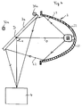
- FIGS. 4 and 5 show a second exemplary embodiment of the lighting device according to the invention with the essential parts.
- the following description relates only to the differences from the first embodiment. It goes without saying that the above explanations apply analogously to the second exemplary embodiment. For reasons of better clarity, in FIGS. 3 and 4, the filter arrangement 5 and the lens 41 are not shown.
- the second exemplary embodiment differs from the first one essentially in that the deflection mirror 3 a can be tilted between two positions, wherein in the first position it copies the copying light coming from the light source 2 into the light mixer deflects and in the second position prevents the copying light from entering the light mixer.
- FIG. 4 shows the deflecting mirror 3a in the first position
- FIG. 5 shows the deflecting mirror 3a in the second position.
- the deflecting mirror 3a is rotatably mounted about an axis of rotation D, as is indicated by the double arrow K in FIGS. 4 and 5.
- the axis of rotation D is preferably oriented approximately perpendicular to the connecting line of the two focal points of the ellipsoid reflector 22 and intersects this connecting line approximately in the middle.
- two stops 31a and 32a are provided which fix the two positions of the deflection mirror 3a. If the deflecting mirror 3a is in the first position (FIG. 4), its rear side bears against the first stop 31a. In this position, the deflecting mirror 3a reflects the light into the light mixer, as is symbolically indicated by the two light beams L1, L2. In order to tilt the deflecting mirror 3a into the second position (FIG.
- the deflecting mirror is rotated about the axis of rotation D, for example by motor drive means (not shown) - in the representation selected in FIG. 4 or FIG. 5 clockwise - until the back of the deflecting mirror 3a bears against the second stop 32a. If the deflecting mirror 3a is in this second position, the light deflected by it can no longer reach the light mixer 4, as is symbolically represented by the two light beams L3, L4 in FIG. 5. It goes without saying that the light source 2 and the light shaft 4 are arranged relative to one another in such a way that light beams emitted by the light source 2 and which do not strike the deflecting mirror 3a cannot reach the light mixer 4. This situation is symbolically represented in FIG. 5 by the light beam L5.
- the second exemplary embodiment of the lighting devices according to the invention has the advantage that the deflecting mirror 3a, in addition to the functions already explained above, also assumes the function of a shutter device with which the copying light can be kept away from the photographic copying material after exposure. This measure makes it possible to dispense with additional closure devices, which results in a further reduction in the components required and thus in the outlay.
- the deflection mirror 3a Before the exposure of a copy original begins, the deflection mirror 3a is in the second position (FIG. 5), so that the copy light is kept away from the copy material. After, for example, in the case of a subtractive exposure process If the transmission filter for coloring the copying light are brought into the correct position or, in the case of an additive exposure process, the exposure times for the three primary colors are known, the deflection mirror 3a is tilted into the first position (FIG. 4) so that the copying light acts on the copying material can. After the exposure time has elapsed, the deflecting mirror 3a is tilted back into the second position (FIG. 5) and thus prevents a further exposure of the copying material to copying light.
- a variant of the embodiment of the second exemplary embodiment consists in placing the second stop 32a in such a way that the reflecting surface of the deflection mirror 3a, when it is in the second position, lies parallel to the light entry surface of the light mixer 4.
- the lighting device according to the invention thus has the advantage that a plurality of functions, which have hitherto usually been performed by a plurality of components, ie H. physically separate units, were taken over in the lighting device according to the invention by only one structural unit, namely the deflection mirror 3; 3a.
- the deflecting mirror 3; 3a serves on the one hand to supply the copying light emitted by the light source 2 to the light mixer 4, and on the other hand, due to its transparency in the infrared wavelength range, it ensures efficient dissipation of the heat radiation of the light source 2 from the illumination beam path.
- due to its selective, spectrally narrow-band reflectivity in the visible wavelength range it limits the copying light to three narrow-band wavelength ranges.
- the deflecting mirror 3a can also serve as a closure device. This concentration of the functions on only one structural element results in a significant reduction in effort, without the need for. B. the advantages of spectrally narrow-band exposure or efficient heat protection must be dispensed with.
Landscapes
- Physics & Mathematics (AREA)
- General Physics & Mathematics (AREA)
- Light Sources And Details Of Projection-Printing Devices (AREA)
Priority Applications (1)
| Application Number | Priority Date | Filing Date | Title |
|---|---|---|---|
| EP96810324A EP0809134A1 (fr) | 1996-05-22 | 1996-05-22 | Dispositif d'éclairage pour une imprimante photographique |
Applications Claiming Priority (1)
| Application Number | Priority Date | Filing Date | Title |
|---|---|---|---|
| EP96810324A EP0809134A1 (fr) | 1996-05-22 | 1996-05-22 | Dispositif d'éclairage pour une imprimante photographique |
Publications (1)
| Publication Number | Publication Date |
|---|---|
| EP0809134A1 true EP0809134A1 (fr) | 1997-11-26 |
Family
ID=8225611
Family Applications (1)
| Application Number | Title | Priority Date | Filing Date |
|---|---|---|---|
| EP96810324A Withdrawn EP0809134A1 (fr) | 1996-05-22 | 1996-05-22 | Dispositif d'éclairage pour une imprimante photographique |
Country Status (1)
| Country | Link |
|---|---|
| EP (1) | EP0809134A1 (fr) |
Citations (3)
| Publication number | Priority date | Publication date | Assignee | Title |
|---|---|---|---|---|
| US3831021A (en) * | 1972-06-09 | 1974-08-20 | Durst Ag | Illuminating device, particularly for photographic enlarging apparatus |
| JPS57100420A (en) * | 1980-12-16 | 1982-06-22 | Ricoh Co Ltd | Copying method |
| DE3615284A1 (de) * | 1986-05-06 | 1987-11-12 | Koenigk Elektronik Fofotech | Vorrichtung und verfahren zur erstellung von farbpositiv-abzuegen |
-
1996
- 1996-05-22 EP EP96810324A patent/EP0809134A1/fr not_active Withdrawn
Patent Citations (3)
| Publication number | Priority date | Publication date | Assignee | Title |
|---|---|---|---|---|
| US3831021A (en) * | 1972-06-09 | 1974-08-20 | Durst Ag | Illuminating device, particularly for photographic enlarging apparatus |
| JPS57100420A (en) * | 1980-12-16 | 1982-06-22 | Ricoh Co Ltd | Copying method |
| DE3615284A1 (de) * | 1986-05-06 | 1987-11-12 | Koenigk Elektronik Fofotech | Vorrichtung und verfahren zur erstellung von farbpositiv-abzuegen |
Non-Patent Citations (2)
| Title |
|---|
| PATENT ABSTRACTS OF JAPAN vol. 6, no. 188 (P - 144) 28 September 1982 (1982-09-28) * |
| PATENT ABSTRACTS OF JAPAN vol. 7, no. 117 (P - 198) 21 May 1983 (1983-05-21) * |
Similar Documents
| Publication | Publication Date | Title |
|---|---|---|
| DE69612489T2 (de) | Beleuchtungseinheit für eine optische vorrichtung | |
| DE2908742C2 (de) | Farbmuster | |
| DE4301716A1 (fr) | ||
| DE19836337C1 (de) | Vorrichtung und Verfahren zum Belichten von Bildinformationen auf lichtempfindliches Aufzeichnungsmaterial | |
| EP0815476B1 (fr) | Systeme optique a vastes champs de mesure | |
| DE69014000T2 (de) | Gebrauch eines LCD's in einer Kopiervorrichtung und Methode. | |
| EP0809134A1 (fr) | Dispositif d'éclairage pour une imprimante photographique | |
| DE3708258C2 (de) | Bildübertragungssystem | |
| DE69809869T2 (de) | Vakuum-Fluoreszenzfarbdruckkopf für photographisches Druckpapier | |
| DE3641635C2 (de) | Verfahren und Vorrichtung zum Steuern der Belichtung in drei Grundfarben beim Farbkopieren | |
| DE69426097T2 (de) | Selektive optische Elemente für einen vielwellenlängen elektronischen Druckkopf | |
| DE3615284C2 (fr) | ||
| DE69503326T2 (de) | Verfahren und Gerät zum Schreiben auf ein lichtempfindliches Material mittels eines modulierten Lichtstrahles | |
| DE1522310A1 (de) | Farbkopf insbesondere zur Verwendung in Vergroesserungsapparaten | |
| DE60036185T2 (de) | Lithographischer Apparat mit Filter | |
| DE1256531B (de) | Hilfsbelichtungseinrichtung fuer Reproduktions- und Vergroesserungsgeraete | |
| DE69014608T2 (de) | Filmdetektor. | |
| DE2912503A1 (de) | Lampengehaeuse zur verwendung bei der herstellung von kopien und einrichtung zum herstellen von kopien | |
| DE3050326C2 (de) | Verfahren zur Behandlung, Registrierung und Beobachtung von Objekten mittels eines höchststrahlenden Lasermediums | |
| EP0586771B1 (fr) | Système d'illumination pour copieurs photographiques | |
| DE3140052C2 (fr) | ||
| DE19511196A1 (de) | Optische Prüfvorrichtung | |
| DE69510306T2 (de) | System zur Verbesserung des Lichthofschutzes/Konturschärfe von photothermographischen Materialien | |
| DE69414141T2 (de) | Fotoprinter | |
| EP0987587A2 (fr) | Dispositif et procédé pour diviser ou combiner un faisceau lumineux |
Legal Events
| Date | Code | Title | Description |
|---|---|---|---|
| PUAI | Public reference made under article 153(3) epc to a published international application that has entered the european phase |
Free format text: ORIGINAL CODE: 0009012 |
|
| AK | Designated contracting states |
Kind code of ref document: A1 Designated state(s): DE |
|
| RBV | Designated contracting states (corrected) |
Designated state(s): DE |
|
| STAA | Information on the status of an ep patent application or granted ep patent |
Free format text: STATUS: THE APPLICATION IS DEEMED TO BE WITHDRAWN |
|
| 18D | Application deemed to be withdrawn |
Effective date: 19980527 |