EP0809068A2 - Brûleur à charbon pulvérisé - Google Patents
Brûleur à charbon pulvérisé Download PDFInfo
- Publication number
- EP0809068A2 EP0809068A2 EP97108022A EP97108022A EP0809068A2 EP 0809068 A2 EP0809068 A2 EP 0809068A2 EP 97108022 A EP97108022 A EP 97108022A EP 97108022 A EP97108022 A EP 97108022A EP 0809068 A2 EP0809068 A2 EP 0809068A2
- Authority
- EP
- European Patent Office
- Prior art keywords
- pulverized coal
- fuel nozzle
- central axis
- flow
- downstream side
- Prior art date
- Legal status (The legal status is an assumption and is not a legal conclusion. Google has not performed a legal analysis and makes no representation as to the accuracy of the status listed.)
- Granted
Links
Images
Classifications
-
- F—MECHANICAL ENGINEERING; LIGHTING; HEATING; WEAPONS; BLASTING
- F23—COMBUSTION APPARATUS; COMBUSTION PROCESSES
- F23D—BURNERS
- F23D1/00—Burners for combustion of pulverulent fuel
-
- F—MECHANICAL ENGINEERING; LIGHTING; HEATING; WEAPONS; BLASTING
- F23—COMBUSTION APPARATUS; COMBUSTION PROCESSES
- F23D—BURNERS
- F23D2201/00—Burners adapted for particulate solid or pulverulent fuels
- F23D2201/20—Fuel flow guiding devices
-
- F—MECHANICAL ENGINEERING; LIGHTING; HEATING; WEAPONS; BLASTING
- F23—COMBUSTION APPARATUS; COMBUSTION PROCESSES
- F23D—BURNERS
- F23D2209/00—Safety arrangements
- F23D2209/20—Flame lift-off / stability
Definitions
- the present invention relates to a pulverized coal burner which transfers pneumatically and burns pulverized coal and, more particularly, to a pulverized coal burner which raises the stability of flame in a low load operation and suppresses occurrence of nitrogen oxides.
- Pulverized coal burning is required to suppress occurrence of nitrogen oxides (hereunder, referred to as NOx) to a small amount.
- NOx nitrogen oxides
- Most of NOx generated during burning of pulverized coal are NOx generated by oxidation of nitrogen contained in the coal.
- various constructions of pulverized coal burners have been proposed.
- a pulverized coal burner which decreases an amount of NOx generated in burning
- a pulverized coal burner in which a reducing zone and oxidizing zone are formed, that is, a so-called flame-inside-two-stage-burning burner.
- Nitrogen in the coal is released into gas phase as cyanide hydrogen (HCN) and ammonia (NH 3 ) during thermal decomposition of pulverized coal at an initial time of combustion.
- Those nitrogen compounds are oxidized to become NOx while they have an effect of reducing NOx in a low oxygen-concentration region.
- the flame inside two stage burning realized effectively, inside flame, a reaction which reduces NOx with NOx precursors such as NH 3 , HCN.
- a reducing zone is expanded by fuel-excess burning with air shortage around the pulverized coal burner in the flame and an oxidizing zone is formed by high oxygen concentration burning at a downstream side of the flame.
- a pulverized coal burner inside which a member is arranged to adjust the particle concentration is disclosed in JP A 63-21406, JP A 3-41571, JP A 3-110308 or JP A 4-24404, for instance.
- a first object of the invention is to solve the above-mentioned problems and to provide a pulverized coal burner in which the stability of flame in a low load operation is raised to improve the burning efficiency of pulverized coal, and the ability of thermal decomposition of pulverized coal in a reducing flame zone is raised to enlarge the reducing flame zone and suppress the occurrence of NOx.
- a second object of the invention is to provide a pulverized coal burner in which an amount of use of a stabilizing fuel such as fuel oil is small by expanding a burner load range in which burning can be effected with fuel of only pulverized coal.
- the present invention is made as follows, that is, in a pulverized coal burner having a fuel nozzle for feeding a mixture of pulverized coal and air and an air nozzle, arranged coaxially with and outside the fuel nozzle, for supplying combustion air in a state of swirling flow, the above-mentioned fuel nozzle comprises a constricted throat for contracting a flow of the mixture toward a central axis of the fuel nozzle, an impinged diffuser having an expanding portion, provided on a central axis of and on the downstream side of the constricted throat, expanding gradually from an upstream side to an downstream side and causing the mixture to impinge thereon and diffuse thereby, and a flow path divider having a narrowing cylinder portion, provided coaxially with the fuel nozzle on the downstream side of the impinged diffuser and gradually narrowing from an upstream side to a downstream side, and dividing the flow path.
- the burner in which the fuel nozzle has a constricted throat, an impinged diffuser having an expanding portion, and a flow path divider having a narrowing cylinder portion and dividing coaxially the flow path, has the constricted throat reducing a flow path area on the upstream side of the fuel nozzle, so that pulverized coal in the vicinity of the wall surface of the fuel nozzle impinges on a flow inlet of the constricted throat and the concentration of the pulverized coal is raised thereby.
- the impinged diffuser having an expanding portion arranged on the downstream side of the constricted throat causes the pulverized coal of a central portion of the fuel nozzle to impinge thereon to raise the concentration and causes the pulverized coal particles concentrated by the constricting portion to impinge thereon. That is, fuel on outer and inner sides in the fuel nozzle impinges on an outer surface of the expanding portion of the impinged diffuser, with the concentration being raised. Thereby, a flow direction of particles is shifted to the outer side in the fuel nozzle and the pulverized coal concentration also is raised there.
- the pulverized coal particles which is changed in the flow direction by the expanding portion of the impinged diffuser and made higher in the concentration, maintains temporarily their flow direction by their inertia, whereby pulverized coal of relatively large particles are collected to an opening edge portion of the fuel nozzle.
- the flow divider on the downstream side of the impinged diffuser divides coaxially the flow path of the fuel nozzle, rectifies pulverized coal flows in the outer flow path and inner flow path. That is, by arranging the flow path divider, flows of carrier air in the outer and inner flow paths become equal to each other, and a radial gradient of speed is decreased.
- the fuel concentration on the outer side divided by the flow path divider becomes high, it is possible to maintain stably flame even at a time of low load operation in which the fuel concentration is low and even with low-volatile coal.
- the ability of thermal decomposition of pulverized coal in the reducing flame zone, particularly, stability of flame at a time of low load operation are raised and occurrence of NOx is suppressed.
- the above-mentioned fuel nozzle comprises a constricted throat for contracting a flow of the mixture toward a central axis of said fuel nozzle, an impinged diffuser having an expanding portion, provided on a central axis of and on the downstream side of the constricted throat, expanding gradually from an upstream side to an downstream side and causing the mixture to impinge thereon and diffuse thereby, and a flow path divider having a narrowing cylinder portion, provided coaxially with the fuel nozzle on the downstream side of the impinged diffuser and gradually narrowing from an upstream side to a downstream side, and dividing coaxially the flow path.
- a burner in which the fuel nozzle has the constricted throat, the impinged diffuser having an expanding portion, and the flow path divider having the narrowing cylinder portion and dividing coaxially the flow path has the same operation as the above-mentioned pulverized coal burner provided with the air nozzle on the both sides of the fuel nozzle.
- the impinged diffuser has a parallel portion, being parallel to the central axis of the fuel nozzle and provided on the central axis of the fuel nozzle so as to extend from the expansion portion, and a narrowing portion, narrowing from an upstream side to a downstream side, and provided on the central axis of the fuel nozzle so as to extend from the parallel portion.
- the burner in which the impinged diffuser has the parallel portion which extends from the expanding portion and is parallel to the central axis, and the narrowing portion which extends from the parallel portion and gradually narrows along the central axis, changes the mixture flow direction to a direction along the central axis of the fuel nozzle by the parallel portion in addition to the operation of any above-mentioned burners, whereby relatively fine particles flow in the vicinity of the outer surface of the parallel portion and the concentration of particles becomes lean.
- the narrowing portion operates so that the mixture flows along the outer surface of the narrowing portion, and since the relative fine particles flowing in the vicinity of the parallel portion follows the gas flowing on the outer surface of the narrowing portion, a concentration gradient in the radial direction of the fuel nozzle is further increased (pulverized coal of relatively fine particles is fed to the furnace from a central portion in the outlet of the fuel nozzle and pulverized coal of relatively large particles is fed from an outer side in the outlet of the fuel burner).
- the apex angle of the expansion portion of the impinged diffuser is in a range from 15° to 40° .
- the apex angle of the expanding portion of the impinged diffuser is in a range from 15° to 40°
- classification of particles by the impinged diffuser is most effectively carried out.
- the apex angle of the expanding portion is 15° or less, change in the flow direction at the expanding portion is small, so that speed component in the diameter direction of the fuel nozzle becomes small and the classification of the particles becomes very weak.
- the apex angle of the expanding portion becomes 40° or more, the surface of the expanding portion becomes likely to be worn by the impingement of particles, and pressure loss of the fuel nozzle increases.
- an apex angle of the narrowing portion of the impinged diffuser is in a range from 5° to 20° .
- the apex angle of the narrowing portion of the impinged diffuser is in a range from 5° to 20
- the flow is not separated at the outer surface of the narrowing portion and the classification of particles is maintained.
- the apex angle of the narrowing portion becomes 5° or less
- the impinged diffuser becomes too large to be accommodated within the fuel nozzle.
- the apex angle of the narrowing portion becomes 20° or more, the flow is separated at the outer surface of the narrowing portion, so that the classification of particles is extremely lowered.
- the above-mentioned flow path divider has a parallel cylinder portion which is provided coaxially with the central axis of the fuel burner to be parallel to the central axis and extend from the narrowing portion.
- feeding speed directions in the outer side and in the inner side of the parallel cylinder portion can be same as each other because both of fuel flows in the inner and outer sides of the parallel cylinder portion flow along the parallel flow portion, so that even after being jetted into a furnace, mixing of fuel jet flow in a radial direction can be suppressed.
- NOx-reducing reaction can be promoted and the concentration of NOx emitted from the pulverized coal burner can be lowered.
- a projection area of the parallel cylinder portion toward the furnace is one corresponding to the thickness of the plate and can be made very small, radiation from the furnace becomes small and burning damage of the pulverised coal burner at time of oil burning, and at idle time can be prevented. Further, since an amount of air necessary for cooling can be made small, an excess air amount is reduced and the thermal efficiency of the furnace can be raised.
- an angle between the outer surface of the abovementioned narrowing portion and the central axis of the fuel burner is in a range 2° to 10° .
- the angle between the outer surface of the narrowing portion and the central axis of the fuel burner is in a range 2° to 10°
- a flow of the mixture is separated from the outer surface of the narrowing cylinder portion and can not flatten a flow distribution on the downstream side.
- the angle between the outer surface of the narrowing portion and the central axis of the fuel burner is less than 2° , the narrowing cylinder portion is elongated, so that it can not be accommodated within the fuel nozzle and the flattening operation of the flow distribution on the downstream side becomes extremely small. Therefore, the angle is desirable to be in a range 2° to 10° .
- the fuel nozzle comprises a constricted throat for contracting a flow of the mixture so as to cause the flow to approach from one side wall to other side wall, an impinged diffuser approaching the flow from an upstream side to a downstream side and the one side wall to the other side wall on the downstream side of the constricted throat, and causing the mixture to impinge and to diffuse, and a flow path divider dividing the flow path on the downstream side of the impinged diffuser.
- the burner which has the constricted throat for contracting a flow of the mixture so as to cause the flow to approach from one side wall to other side wall, the impinged diffuser gradually approaching the flow from one side wall to the other side wall, and causing the mixture to impinge on to diffuse, and the flow path divider dividing the flow path, has the same operation as the previously mentioned pulverized coal burner provided with the air nozzles supplying combustion air on both sides of the fuel nozzle, and can form stable flame in the vicinity of the pulverized coal burner, so that thermal decomposition of pulverized coal is promoted and the concentration of NOx is reduced.
- the fuel nozzle has, at its tip portion, a deflection plate for deflecting a flow of combustion air for the air nozzle toward an outside and impingement plates for causing the mixture to impinge thereon.
- the deflection plate deflects flow of combustion air from the tip portion of the burner outside.
- the impingement plates cause eddies or vortexes at the tip portion of the fuel nozzle, enlarge a reverse flow zone of the mixture formed on the downstream side of the fuel nozzle tip, an igniting position of pulverized coal approaches the pulverized coal burner, and the combustion efficiency of pulverized coal increases. Additionally, the temperature becomes high at a position close to the pulverized coal burner, and consumption of oxygen increases, so that the reducing flame zone becomes large and occurrence of NOx is suppressed.
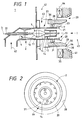
- Fig. 1 is a sectional view of a first embodiment of the pulverized coal burner according to the present invention.
- Fig. 2 is a view viewed from an arrow I of Fig.1.
- the pulverized coal burner 1 of the first embodiment is a burner suitable for a pulverised coal burning boiler which burns pulverized coal and generates steam, and the burner has a fuel nozzle 2, provided at a position of a central axis, for feeding a mixture 62 of pulverized coal and primary air. Further, a secondary air nozzle 27 and a third air nozzle 33 for supplying, as combustion air in a state of swirling flow, secondary air 63 and third air 64, respectively, are provided outside and coaxially with the fuel nozzle 2.
- the two air nozzles 27, 33 are flow paths for supplying the combustion air supplied in a wind-box 42 into a furnace 43.
- the fuel nozzle 2 is a tubular flow path, the outer wall of which is a primary throat 23, and has an oil gun 22, for feeding a stabilizing fuel, mounted on a central axis 3 of the fuel nozzle 2, to preheat water pipes 41 mounted on the inner wall of the furnace 43.
- the fuel nozzle 2 has a venturi 4 which is a constricted throat contracting a flow of the mixture 62 from an upstream side toward the side of the central axis 3 of the fuel nozzle 2, a spindle 9 which is an impinged diffuser provided coaxially with the central axis of the fuel nozzle on the downstream side of the venturi 4, gradually expanding from an upstream side to a downstream side and causing the mixture 62 to impinge thereon and diffuse, and a distributor 14, which is a flow path divider dividing coaxially the flow path, provided coaxially with the central axis of the fuel nozzle on the downstream side of the spindle 9, and having a cone 15 which is a narrowing cylinder portion gradually narrowing from the upstream side to the downstream side.
- the fuel nozzle 2 has a stabilizer 19 at a tip thereof.
- the stabilizer 19 has a deflection plate 20 deflecting a flow of secondary air 63 of the secondary air nozzle, and impingement plates 21 for causing the mixture 62 to impinge thereon.
- a plurality of the impingement plates 21 are mounted in a circumferential direction.
- the venturi 4 is for raising the concentration of pulverized coal transferred from a pulverized coal supply apparatus not shown in Fig. 1 and supplying the pulverized coal, and the area of the minimum flow path cross-section thereof is 30 to 70% of the flow path cross-sectional area of the fuel nozzle 2, whereby a drift of particles by a bent pipe portion, etc. at the upstream side of the fuel nozzle 2 can be suppressed.
- the spindle 9 has a cone 10 which is an expanding portion, a column 11 which is a parallel portion extending from the cone 10 to be coaxial and parallel with the central axis 3 of the fuel nozzle 2, and a cone 12 which is a narrowing portion extending from the column 11, provided coaxially with the central axis 3 of the fuel nozzle and gradually narrowing from the upstream side to the downstream side.
- the apex angle of the cone 10 is 15-40° and the apex angle of the cone 12 which is the narrowing portion is 5-20° .
- the distributor 14 has a cylinder 17 which is a parallel cylinder portion extending from the cone 15 to be coaxial with and parallel to the central axis 3 of fuel nozzle.
- An angle between the outer surface of the cone 15 and the central axis 3 of the fuel nozzle is 2-10° .
- the secondary air nozzle 27 is an annular flow path, the inner wall of which is the primary throat 23 and the outer wall is a secondary throat 28.
- the annular flow path is provided with secondary air swirling vanes 31 and a damper 36 on the flow path from the furnace 43 to the upstream side.
- the secondary air swirling vanes 31 supply secondary air 63 while swirling it.
- the secondary air swirling vanes 31 are axial flow type swirling flow generators, and have a plurality of vanes arranged in the flow path in a peripheral direction and a supporting bar integrating the vanes. The intensity of the swirling flow passing through the secondary air swirling vanes 31 is adjusted by changing an angle of the vanes by a drive apparatus not shown.
- the damper 36 which adjusts a flow rate of secondary air 63 and has a cylindrical shape, is mounted at the position covering an opening communicating the secondary throat 28 and the wind-box 42, and moved in a direction parallel with the central axis of the burner by an adjustor not shown in Fig. 1 to change an area of the above-mentioned opening. By this operation, a distribution ratio of secondary air 63 and third air 64 is adjusted.
- the third air nozzle 33 is an annular flow path, the inner wall of which is a third throat 34 and the outer wall of which is a burner throat 38.
- Third air 64 from the wind-box 42 is swirled and supplied into the furnace 43 through third air swirling vanes 35.
- the secondary throat 28 and third throat 34 are separated in a radial direction, and the partitioning portion has a diameter-expanded portion 29 that a furnace side end face of the secondary throat 28 is axially extended while being expanded in a radial direction, and a partition wall 30 which is a perpendicular annular wall face facing the furnace 43.
- the pulverized coal burner 1 of the first embodiment having the above-mentioned construction that is, the burner 1 in which the fuel nozzle 2 has the venturi 4, the spindle 9 with the cone 10, and the distributor 14 having the cone 15 and dividing coaxially the flow path, operates as follows.
- the pulverized coal flowing in the vicinity of the wall of the fuel nozzle 2 impinges on the wall surface of the venturi 4 on the inflow side, whereby the concentration thereof is raised.
- the spindle 9 arranged downstream of the venturi 4 causes the pulverized coal raised in concentration to impinge on the outer surface of the cone 10, thereby to direct the flow direction to the inner wall surface of the fuel nozzle 2.
- the pulverized coal of high concentration can flow in the vicinity of the inner wall of the fuel nozzle 2.
- the flow direction of the mixture 62 is changed to a direction along the central axis of the fuel nozzle 2 by the column 11, and relatively fine particles flow in the vicinity of the outer surface of the column 11 and the concentration is lowered there.
- the cone 12 operates the mixture 62 so as to flow along the outer surface of the cone 12, and relatively fine particles flowing in the vicinity of the column 11 follow the gas flowing on the outer surface of the cone 12, and a concentration gradient in the radial direction of the fuel nozzle 2 is further increased.
- the apex angle of the cone 10 of the spindle 9 is 15-40° .
- classification of particles is effectively performed by the spindle 9.
- the apex angle of the cone 9 is 15° or less, since a change of the flow direction at the cone 10 is small, a speed component in the radial direction of the fuel nozzle 2 becomes small, and classification of particles at the column 11 becomes extremely weak.
- the apex angle of the cone 10 is made 40° or more, the outer surface of the cone 10 is easily worn away by impingement of the particles and pressure loss of the fuel nozzle 2 increases.
- the spindle 12 of the spindle becomes larger so that it can not be accommodated within the fuel nozzle 2.
- the apex angle of the cone 12 becomes 20° or more, since the flow is separated at the outer surface of the cone 12, the classification of particles is extremely lowered.
- the apex angle of the cone 12 on the downstream side is desirable to be smaller than the apex angle of the cone 10 on the upstream side.
- the pulverized coal particles changed in flow direction thereof by the spindle 9 and having a high concentration, maintain temporarily their flow direction by their inertia, whereby pulverized coal particles of relatively large diameter are collected to an opening edge portion of the fuel nozzle 2.
- the openign edge portion is an outer side portion in the outlet of the fuel nozzle, including stabilizer plates 19.
- the flow path of the fuel nozzle 2 is coaxially divided by providing the distributor 14 on the downstream side of the spindle 9, flows of pulverized coal in the outer flow path and the inner flow path are rectified. That is, by arranging the distributor 14, carrier air in the outer side and the inner side are made equal to each other and a speed gradient in the radial direction is decreased.
- the concentration of pulverized coal in the outer side of the distributor 14, divided by the distributor 14 becomes high, flame can be stably maintained even with low-volatile coal, and even at a time of low load operation in which low concentration pulverized coal is used, the ability of thermal decomposition of pulverized coal in the reducing flame zone, particularly, the stability of flame at a low load is raised, and occurrence of NOx is suppressed.
- the burner in which the distributor 14 has the cylinder 17 extending from the cone 15 and being parallel to the central axis, can jet fuel inside and outside the cylinder 17 in the same direction as each other, so that even after feeding into the furnace, mixing of fuel jet flows in the radial direction can be suppressed. Thereby, more amount of fuel of small diameter particles can be supplied in the NOx reducing zone, NOx reduction can be promoted, and the concentration of NOx discharged from the pulverized coal burner is decreased.
- a projection area of the cylinder 17 to the direction of the furnace is only an area corresponding to the thickness of a plate, and can be made very small, so that radiation from the furnace becomes small and burning damage of the pulverized coal burner at a time of oil burning and at a idling time can be prevented. Further, since an amount of air necessary for cooling can be made small, it is possible to decrease excess air and raise the thermal efficiency of the furnace.
- an angle between the outer surface of the cone 15 and the central axis 3 of the fuel nozzle exceeds 10° , the flow of the mixture 62 is separated from the outer surface of the cone 15 and it is impossible to flatten a flow speed distribution on the downstream side.
- the angle between the outer surface of the cone 15 and the central axis 3 of the fuel nozzle is less than 2° , the length of the cone 15 becomes long, so that it can not be accommodated within the fuel nozzle and the speed distribution can not be flattened on the downstream side. Therefore, the angle between the outer surface of the cone 15 and the central axis 3 of the fuel nozzle is desirable to be in a range of 2 to 10° .
- the deflection plate 20 deflects the flow of secondary air from the tip 7 of the fuel nozzle to the outside.
- the impingement plates 21 generate eddies or vortexes in the vicinity of the tip 7 of the fuel nozzle. As shown in Fig.
- the size of the reverse flow zone formed downstream of the stabilizer 19 of the fuel nozzle 2 is determined according to the swirling intensity of secondary air 63. Therefore, even under the condition that a flow rate of combustion air is small, the scale of a reverse flow zone formed right downstream of the stabilizer 19 becomes equal to that under the condition that a flow rate of the combustion air is large, by increasing a flow rate of secondary air 63 occupied in the combustion air or increasing swirling speed component by changing the angle of the secondary air swirling vanes 31.
- the pulverized coal burner 1 of the present embodiment has the following excellent points by providing the distributor 14 having the cone 15, compared with a guide cylinder disclosed, for example, in JP A 3-110308.
- the pressure loss of the flow path on the inner side of the distributor 14 can be made small.
- a flow rate of carrier air including pulverized coal of high concentration flowing in the outer pipe passage of the distributor 14 becomes large, and a ratio of pulverised coal distributed in a high concentration side increases. Therefore, it is possible to widen a region of a high pulverized coal concentration at the opening edge portion of the fuel nozzle 2. Since the thickness of a fuel jet flow of high concentration in the radial direction increases, it is possible to maintain the fuel jet flow of high concentration even inside the furnace, reducing atmosphere within flame can be effectively generated and pulverized coal can be burnt with low NOx emission.
- the upstream side end of the distributor 14 can be approached to the wall surface of the fuel nozzle 2. Since the concentration of pulverized coal is higher as it is closer to the wall surface of the fuel nozzle 2, the concentration of pulverized coal on the outer side divided out by the distributor 14 becomes high, flame can be maintained stably even at a time of a low load operation in which low concentration fuel is used, and at a time of burning of low-volatile coal.
- downstream side end of the distributor 14 is parallel to the central axis of the fuel nozzle 2, and jetting speed in the outer side and the inner side of the distributor can be same in direction, even after being jetted into the furnace, mixing of fuel jet flows in the radial direction can be suppressed. Thereby, since more amount of fuel of small diameter particles can be supplied to the NOx reducing zone, NOx reducing reaction is promoted, and the concentration of NOx emitted from the burner decreases.
- a projection area, of the distributor 14 to the direction of the furnace, in the vicinity of the end surface of the downstream side is only an area corresponding to the thickness of the plate, and can be made very small.
- the above-mentioned projection area is small, radiation from the furnace becomes small.
- the pulverized coal burner becomes difficult to suffer burning damage.
- an amount of air necessary for cooling can be made small, it is possible to decrease excess air and raise the thermal efficiency of the boiler.
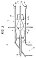
- Fig. 3 is a sectional view, a part of which is omitted, of a second embodiment similar to Fig. 1.
- a distributor 14 which is a flow path divider is made of only a cone 15 which is a narrowing cylinder portion, and by this, flow speed distribution on the downstream side of the spindle 9 is flattened.
- An angle of the cone 15 is desirable to be in a range of 2 to 10° . As mentioned above, in the range of the angle, separation of a mixture flow from the outer side surface of the cone 15 is suppressed.
- the pulverized coal burner of the second embodiment has an object to flatten the flow speed distribution on the downstream side of the cone 15.
- it is necessary to flow air along the inner peripheral surface and the outer peripheral surface of the cone 15. Therefore, it is particularly important that air flows along the outer peripheral surface, and separation of air at the outer peripheral surface of the cone 15 should be suppressed.
- Once air flow is separated particles can not diffuse into the separated flow and the particles are carried to the tip of the fuel nozzle as they are.
- Conditions of separation of air at the outer peripheral surface were measured in detail, as a result, it is found clear that the angle of the cone is desirable to be in a range of 2 to 10° .
- the fuel nozzle 2 of the pulverized coal burner of the present embodiment as mentioned above can raise the concentration of fuel at the opening edge portion of the nozzle to about twice the concentration under the transfer conditions. Further, the flow speed distribution can be flattened within +-5% of an average flow speed. Thereby, pulverized coal becomes easy to be ignited, so that denitration reaction in the flame is promoted and the concentration of NOx can be decreased. In case where bituminous coal of fuel ratio 2.3 is burnt and it is compared under the condition of unburnt substance 5% in ash at the furnace outlet, the concentration of NOx is reduced by 20% compared with conventional one.
- the pulverized coal burner 1 of the invention is most desirable to be a burner constructed of a fuel nozzle 1, a secondary air nozzle 27 and a third air nozzle 33, however, provision of one auxiliary air nozzle can be sufficient instead of providing separately the secondary air nozzle 27 and the third air nozzle 33.
- a stabilizing function of this burner is based on the fact that a negative pressure portion is formed which is lower in atmospheric pressure in the vicinity of the outlet end of the fuel nozzle than its surroundings, circulation flows of pulverized coal and air occur there, and ignitability becomes good.
- pulverized coal the concentration of which is made higher than at the outlet of a pulverizer, is supplied into the negative pressure portion of the nozzle outlet portion.
- an upstream side portion of the flow path divider 14 is excellent to be the cone 15 which is the narrowing cylinder the diameter of which changes to be smaller toward the downstream side.
- the flow path divider is provided so that the small diameter portion thereof is positioned on the upstream side, it is difficult to change independently the concentration distribution and the flow speed concentration at the outlet of the fuel nozzle 2. Further, it is apt to receive radiation from the furnace and problems such as thermal deformation and burning damage occur.
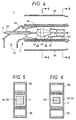
- Fig. 4 is a sectional view, of a third embodiment, similar to Fig. 1.
- Fig. 5 is a sectional view taken along a line II-II of Fig. 4
- Fig. 6 is a sectional view taken along a line III-III of Fig. 4.
- the pulverized coal burner 1 of the first or second embodiment has a circular cross-section.
- the present invention can be applied to a rectangular burner in which the flow path has a rectangular cross-section.
- the pulverised coal burner 1 of the third embodiment has air nozzles 55 for supplying combustion air on both sides of a fuel nozzle 2 for feeding mixture 62 of pulverized coal and air.
- the fuel nozzle 2 is provided with a constricted throat 45 contracting flow of mixture 62 toward the central axis 3 of the fuel nozzle, an impinged diffuser having an expansion portion 47 provided on the central axis 3 of the fuel burner on the downstream side of the constricted throat 45, gradually expanding the upstream side to the downstream side and causing the mixture 62 to impinge thereon to diffuse, a parallel portion 48 and a narrowing portion 49, and a flow path divider 50, provided coaxially with the central axis 3 of the fuel nozzle on the downstream side of the impinged diffuser 46, and dividing coaxially the flow path, the flow path divider having a narrowing cylinder portion 51 narrowing gradually from the upstream side to the downstream side and a parallel cylinder portion 52 extending from the narrowing cylinder portion 51.
- the fuel nozzle 2 and the air nozzles 55 each have a rectangular shape, and the air nozzles 55 are provided on upper and lower sides of the fuel nozzle 2 so as to be adjacent thereto.
- the constricted throat 45, the impinged diffuser 46, the flow path divider 50, etc. arranged inside the fuel nozzle 2 also are rectangular in cross-section.
- the highest performance is exhibited, however, even in a case where the fuel nozzle itself is rectangular in cross-section, and sectional shapes of the constricted throat 45, the impinged diffuser 46, the flow path divider 50, etc. are circular, virtually the same performance is exhibited.
- the fuel burner 2 is provided with the constricted throat 45, the impinged diffuser 46 and the flow path divider 50, whereby the pulverized coal burner provided with the air nozzles on the both sides of the fuel nozzle, has a similar operation to the previously mentioned pulverized coal burner.
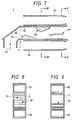
- Fig. 7 is a sectional view, of a fourth embodiment, similar to Fig. 1, Fig. 8 is a sectional view taken along a line IV-IV of Fig. 7, and Fig. 9 is a sectional view taken along a line V-V of Fig. 7.
- the pulverized coal burner 1 of the forth embodiment has an air nozzles 55 supplying combustion air on both sides of a fuel nozzle 2 jetting mixture 62 of pulverized coal and air.
- the fuel nozzle 2 is provided with a constricted throat 58 contracting flow of mixture 62 from one side wall surface to the other side wall surface, an impinged diffuser 59 gradually approaching the mixture from the other wall surface to the one wall surface, and from the upstream side to the downstream side, on the downstream side of the constricted throat 58 and causing the mixture 62 to impinge to diffuse, and a flow path divider 60 dividing the flow path on the downstream side of the impinged diffuser 59.
- the constricted throat 58 of the fuel nozzle 2, the impinged diffuser 59, the flow path divider 60 extends uniformly toward the inner part.
- the burner in which the fuel nozzle 2 has the constricted throat 58 contracting flow of mixture 62 from one side wall surface to the other side wall surface, the impinged diffuser 59 gradually approaching the mixture from the other wall surface 57 to the one wall surface 56 and causing the mixture 62 to impinge to diffuse, and the flow path divider 60 dividing the flow path, has an operation similar to the pulverized coal burner of the previous third embodiment (Fig.3), forms stable flame in the vicinity of the pulverized coal burner, promotes thermal decomposition of pulverized coal and reduces the concentration of NOx.
- the stability of flame at a time of low load operation is raised, the combustion efficiency of pulverized coal is improved, and the reducing flame zone is enlarged to suppress occurrence of NOx.
- an amount of use of stabilizing fuel is reduced by enlarging a load range of the burner in which combustion is possible with only pulverized coal.
Applications Claiming Priority (3)
| Application Number | Priority Date | Filing Date | Title |
|---|---|---|---|
| JP12945196 | 1996-05-24 | ||
| JP129451/96 | 1996-05-24 | ||
| JP08129451A JP3099109B2 (ja) | 1996-05-24 | 1996-05-24 | 微粉炭バーナ |
Publications (3)
| Publication Number | Publication Date |
|---|---|
| EP0809068A2 true EP0809068A2 (fr) | 1997-11-26 |
| EP0809068A3 EP0809068A3 (fr) | 1998-09-23 |
| EP0809068B1 EP0809068B1 (fr) | 2003-11-12 |
Family
ID=15009815
Family Applications (1)
| Application Number | Title | Priority Date | Filing Date |
|---|---|---|---|
| EP97108022A Expired - Lifetime EP0809068B1 (fr) | 1996-05-24 | 1997-05-16 | Brûleur à charbon pulvérisé |
Country Status (7)
| Country | Link |
|---|---|
| US (1) | US5937770A (fr) |
| EP (1) | EP0809068B1 (fr) |
| JP (1) | JP3099109B2 (fr) |
| KR (1) | KR100330675B1 (fr) |
| CA (1) | CA2205778C (fr) |
| DE (1) | DE69726048T2 (fr) |
| FI (1) | FI114504B (fr) |
Cited By (13)
| Publication number | Priority date | Publication date | Assignee | Title |
|---|---|---|---|---|
| EP0893649A3 (fr) * | 1997-07-24 | 1999-09-15 | Hitachi, Ltd. | Brûleur à charbon pulvérisé |
| WO2002010645A2 (fr) * | 2000-07-27 | 2002-02-07 | John Zink Company, L.L.C. | Ensemble de tubes venturi, et bruleurs et procedes utilisant ces ensembles |
| EP1312859A1 (fr) * | 2001-11-16 | 2003-05-21 | Hitachi, Ltd. | Brûleur pour combustible solide, procédé de mise en oeuvre de celui-ci, appareil de combustion et son mode opératoire |
| EP1416221A1 (fr) * | 2002-07-11 | 2004-05-06 | Praxair Technology, Inc. | Combustion avec reduction de Nox de courants de charbon concentres |
| AT502123B1 (de) * | 2005-07-06 | 2007-05-15 | Unitherm Cemcon Feuerungsanlag | Brenner |
| AU2005229645B2 (en) * | 2004-11-02 | 2009-01-08 | Babcock-Hitachi K.K. | After-air nozzle for two-stage combustion boiler, and a two-stage combustion boiler, boiler and combustion method using the same |
| WO2009143725A1 (fr) * | 2008-05-29 | 2009-12-03 | 徐州燃烧控制研究院有限公司 | Brûleur à charbon pulvérisé à combustion interne |
| CN101216173B (zh) * | 2007-12-26 | 2011-01-19 | 东方锅炉(集团)股份有限公司 | 一种双旋流粉煤燃烧器 |
| CN102062396A (zh) * | 2010-10-13 | 2011-05-18 | 西安交通大学 | 一种复合浓淡三调风低NOx旋流煤粉燃烧器 |
| CN103267282A (zh) * | 2013-06-11 | 2013-08-28 | 哈尔滨博深科技发展有限公司 | 浓淡分离煤粉燃烧器 |
| US8925323B2 (en) | 2012-04-30 | 2015-01-06 | General Electric Company | Fuel/air premixing system for turbine engine |
| WO2017212256A1 (fr) * | 2016-06-08 | 2017-12-14 | Doosan Babcock Limited | Brûleur |
| WO2018138323A1 (fr) * | 2017-01-27 | 2018-08-02 | Bilfinger Engineering & Technologies Gmbh | Brûleur, notamment brûleur radiant pour lignite |
Families Citing this family (40)
| Publication number | Priority date | Publication date | Assignee | Title |
|---|---|---|---|---|
| JP3343855B2 (ja) * | 1998-01-30 | 2002-11-11 | 株式会社日立製作所 | 微粉炭燃焼バーナ及び微粉炭燃焼バーナの燃焼方法 |
| JP2000257811A (ja) * | 1999-03-03 | 2000-09-22 | Hitachi Ltd | 微粉炭燃焼方法及び微粉炭燃焼装置並びに微粉炭燃焼バーナ |
| US6840183B2 (en) * | 1999-11-15 | 2005-01-11 | Rickey E. Wark | Diffuser insert for coal fired burners |
| US6240859B1 (en) * | 2000-05-05 | 2001-06-05 | Four Corners Group, Inc. | Cement, reduced-carbon ash and controlled mineral formation using sub- and supercritical high-velocity free-jet expansion into fuel-fired combustor fireballs |
| US20020127505A1 (en) * | 2001-01-11 | 2002-09-12 | Hisashi Kobayashi | Oxygen enhanced low nox combustion |
| US6883444B2 (en) * | 2001-04-23 | 2005-04-26 | N-Viro International Corporation | Processes and systems for using biomineral by-products as a fuel and for NOx removal at coal burning power plants |
| US6405664B1 (en) * | 2001-04-23 | 2002-06-18 | N-Viro International Corporation | Processes and systems for using biomineral by-products as a fuel and for NOx removal at coal burning power plants |
| US6474250B1 (en) * | 2001-05-24 | 2002-11-05 | Babcock Borsig Power, Inc. | Nozzle assembly for a pulverized coal burner |
| US6752848B2 (en) | 2001-08-08 | 2004-06-22 | N-Viro International Corporation | Method for disinfecting and stabilizing organic wastes with mineral by-products |
| US6752849B2 (en) | 2001-08-08 | 2004-06-22 | N-Viro International Corporation | Method for disinfecting and stabilizing organic wastes with mineral by-products |
| CA2485570C (fr) | 2002-05-15 | 2009-12-22 | Praxair Technology, Inc. | Combustion avec teneur reduite en carbone dans la cendre |
| CA2485934C (fr) * | 2002-05-15 | 2009-12-15 | Praxair Technology, Inc. | Combustion a faible formation de nox |
| US8689707B2 (en) * | 2006-05-26 | 2014-04-08 | Fuel Tech, Inc. | Ultra low NOx burner replacement system |
| US8113824B2 (en) * | 2006-06-01 | 2012-02-14 | Babcock & Wilcox Power Generation Group, Inc. | Large diameter mid-zone air separation cone for expanding IRZ |
| WO2009009945A1 (fr) * | 2007-07-18 | 2009-01-22 | Harbin Institute Of Technology | Brûleur de charbon pulvérisé à turbulence à faible nox |
| WO2009092234A1 (fr) * | 2007-12-27 | 2009-07-30 | Beijing Guangyao Electricity Equipment Co., Ltd | Canon d'éjection de plasma à ca et son procédé d'alimentation, et un brûleur à charbon pulvérisé |
| US20100021853A1 (en) * | 2008-07-25 | 2010-01-28 | John Zink Company, Llc | Burner Apparatus And Methods |
| US8104412B2 (en) * | 2008-08-21 | 2012-01-31 | Riley Power Inc. | Deflector device for coal piping systems |
| US20100081102A1 (en) * | 2008-09-30 | 2010-04-01 | General Electric Company | Systems and methods for facilitating varying size coal pipes for a pulverized coal burner |
| CN101846315B (zh) * | 2009-03-24 | 2012-07-04 | 烟台龙源电力技术股份有限公司 | 煤粉浓缩装置和包含该煤粉浓缩装置的内燃式煤粉燃烧器 |
| US20100275824A1 (en) * | 2009-04-29 | 2010-11-04 | Larue Albert D | Biomass center air jet burner |
| CN102235666B (zh) * | 2010-04-27 | 2014-11-26 | 烟台龙源电力技术股份有限公司 | 一种煤粉燃烧器及包括该煤粉燃烧器的煤粉锅炉 |
| CN101832550A (zh) * | 2010-06-18 | 2010-09-15 | 上海交通大学 | 基于多级煤粉浓缩的旋流煤粉燃烧器 |
| DE102011018697A1 (de) * | 2011-04-26 | 2012-10-31 | Babcock Borsig Steinmüller Gmbh | Brenner für partikelförmigen Brennstoff |
| JP5658126B2 (ja) * | 2011-11-16 | 2015-01-21 | 三菱重工業株式会社 | 油焚きバーナ、固体燃料焚きバーナユニット及び固体燃料焚きボイラ |
| JP5867742B2 (ja) * | 2012-08-14 | 2016-02-24 | 三菱日立パワーシステムズ株式会社 | 固体燃料バーナを備えた燃焼装置 |
| CN102913943A (zh) * | 2012-10-19 | 2013-02-06 | 金渭圭 | 一种锅炉的燃烧方法及分体式低氮燃烧器 |
| US9513002B2 (en) | 2013-04-12 | 2016-12-06 | Air Products And Chemicals, Inc. | Wide-flame, oxy-solid fuel burner |
| US9377191B2 (en) * | 2013-06-25 | 2016-06-28 | The Babcock & Wilcox Company | Burner with flame stabilizing/center air jet device for low quality fuel |
| CN104566357A (zh) * | 2013-10-29 | 2015-04-29 | 烟台龙源电力技术股份有限公司 | 煤粉燃烧器以及锅炉 |
| US9709269B2 (en) * | 2014-01-07 | 2017-07-18 | Air Products And Chemicals, Inc. | Solid fuel burner |
| CN104791833A (zh) * | 2014-01-21 | 2015-07-22 | 四川川锅锅炉有限责任公司 | 一种面积可调且可摆动的二次风喷嘴 |
| CN104832916A (zh) * | 2014-02-10 | 2015-08-12 | 四川川锅锅炉有限责任公司 | 一种钝体可调节煤粉燃烧器喷嘴 |
| US9416966B2 (en) | 2014-07-25 | 2016-08-16 | Flame Commander Corp. | Venturi nozzle for a gas combustor |
| JP6231047B2 (ja) * | 2015-06-30 | 2017-11-15 | 三菱日立パワーシステムズ株式会社 | 固体燃料バーナ |
| CN105737145B (zh) * | 2016-02-26 | 2017-11-03 | 郑州轻工业学院 | 一种强化浓缩型旋流煤粉燃烧器 |
| US10473327B2 (en) * | 2016-06-09 | 2019-11-12 | General Electric Technology Gmbh | System and method for increasing the concentration of pulverized fuel in a power plant |
| WO2018207559A1 (fr) * | 2017-05-11 | 2018-11-15 | 三菱日立パワーシステムズ株式会社 | Brûleur à combustible solide et dispositif de combustion |
| JP2020030037A (ja) * | 2018-08-20 | 2020-02-27 | 三菱日立パワーシステムズ株式会社 | 固体燃料バーナ |
| CN112902173B (zh) * | 2021-02-07 | 2022-03-04 | 哈尔滨工业大学 | 一种采用高温一二次风燃尽固废的装置 |
Citations (4)
| Publication number | Priority date | Publication date | Assignee | Title |
|---|---|---|---|---|
| JPS6321406A (ja) | 1986-07-14 | 1988-01-29 | Babcock Hitachi Kk | 粉砕燃料逆火防止装置 |
| JPH0341571A (ja) | 1989-07-10 | 1991-02-22 | Fuji Xerox Co Ltd | 画像処理方法および装置 |
| JPH03110308A (ja) | 1989-09-25 | 1991-05-10 | Babcock Hitachi Kk | 微粉炭燃焼装置 |
| JPH0424404A (ja) | 1990-05-21 | 1992-01-28 | Babcock Hitachi Kk | 微粉炭バーナ |
Family Cites Families (8)
| Publication number | Priority date | Publication date | Assignee | Title |
|---|---|---|---|---|
| JP2776572B2 (ja) * | 1989-07-17 | 1998-07-16 | バブコツク日立株式会社 | 微粉炭バーナ |
| EP0445938B1 (fr) * | 1990-03-07 | 1996-06-26 | Hitachi, Ltd. | Brûleur à charbon pulvérisé, chaudière au charbon pulvérisé et procédé pour la combustion de charbon pulvérisé |
| AU643044B2 (en) * | 1990-06-29 | 1993-11-04 | Babcock-Hitachi Kabushiki Kaisha | Combustion system |
| US5199355A (en) * | 1991-08-23 | 1993-04-06 | The Babcock & Wilcox Company | Low nox short flame burner |
| WO1995013502A1 (fr) * | 1993-11-08 | 1995-05-18 | Ivo International Oy | Procede et appareil pour bruler un combustible pulverise |
| JPH07260106A (ja) * | 1994-03-18 | 1995-10-13 | Hitachi Ltd | 微粉炭燃焼バーナ及び微粉炭燃焼装置 |
| CA2151308C (fr) * | 1994-06-17 | 1999-06-08 | Hideaki Ohta | Bruleur a combustible pulverise |
| JP3140299B2 (ja) * | 1994-06-30 | 2001-03-05 | 株式会社日立製作所 | 微粉炭バーナ及びその使用方法 |
-
1996
- 1996-05-24 JP JP08129451A patent/JP3099109B2/ja not_active Expired - Fee Related
-
1997
- 1997-05-16 DE DE69726048T patent/DE69726048T2/de not_active Expired - Fee Related
- 1997-05-16 FI FI972105A patent/FI114504B/fi not_active IP Right Cessation
- 1997-05-16 EP EP97108022A patent/EP0809068B1/fr not_active Expired - Lifetime
- 1997-05-22 CA CA002205778A patent/CA2205778C/fr not_active Expired - Fee Related
- 1997-05-23 KR KR1019970020301A patent/KR100330675B1/ko not_active IP Right Cessation
- 1997-05-23 US US08/862,256 patent/US5937770A/en not_active Expired - Fee Related
Patent Citations (4)
| Publication number | Priority date | Publication date | Assignee | Title |
|---|---|---|---|---|
| JPS6321406A (ja) | 1986-07-14 | 1988-01-29 | Babcock Hitachi Kk | 粉砕燃料逆火防止装置 |
| JPH0341571A (ja) | 1989-07-10 | 1991-02-22 | Fuji Xerox Co Ltd | 画像処理方法および装置 |
| JPH03110308A (ja) | 1989-09-25 | 1991-05-10 | Babcock Hitachi Kk | 微粉炭燃焼装置 |
| JPH0424404A (ja) | 1990-05-21 | 1992-01-28 | Babcock Hitachi Kk | 微粉炭バーナ |
Cited By (28)
| Publication number | Priority date | Publication date | Assignee | Title |
|---|---|---|---|---|
| US6112676A (en) * | 1997-07-24 | 2000-09-05 | Hitachi, Ltd. | Pulverized coal burner |
| EP0893649A3 (fr) * | 1997-07-24 | 1999-09-15 | Hitachi, Ltd. | Brûleur à charbon pulvérisé |
| EP1351017A2 (fr) * | 1997-07-24 | 2003-10-08 | Hitachi, Ltd. | Brûleur à charbon pulvérisé |
| EP1376009A2 (fr) * | 1997-07-24 | 2004-01-02 | Hitachi, Ltd. | Brûleur à charbon pulverisé |
| EP1376009A3 (fr) * | 1997-07-24 | 2004-01-14 | Hitachi, Ltd. | Brûleur à charbon pulverisé |
| EP1351017A3 (fr) * | 1997-07-24 | 2004-01-28 | Hitachi, Ltd. | Brûleur à charbon pulvérisé |
| US6729874B2 (en) | 2000-07-27 | 2004-05-04 | John Zink Company, Llc | Venturi cluster, and burners and methods employing such cluster |
| WO2002010645A2 (fr) * | 2000-07-27 | 2002-02-07 | John Zink Company, L.L.C. | Ensemble de tubes venturi, et bruleurs et procedes utilisant ces ensembles |
| WO2002010645A3 (fr) * | 2000-07-27 | 2002-08-29 | John Zink Co Llc | Ensemble de tubes venturi, et bruleurs et procedes utilisant ces ensembles |
| EP1312859A1 (fr) * | 2001-11-16 | 2003-05-21 | Hitachi, Ltd. | Brûleur pour combustible solide, procédé de mise en oeuvre de celui-ci, appareil de combustion et son mode opératoire |
| US6889619B2 (en) | 2001-11-16 | 2005-05-10 | Hitachi, Ltd. | Solid fuel burner, burning method using the same, combustion apparatus and method of operating the combustion apparatus |
| US7168374B2 (en) | 2001-11-16 | 2007-01-30 | Hitachi, Ltd. | Solid fuel burner, burning method using the same, combustion apparatus and method of operating the combustion apparatus |
| US7665408B2 (en) | 2001-11-16 | 2010-02-23 | Hitachi, Ltd. | Solid fuel burner, burning method using the same, combustion apparatus and method of operating the combustion apparatus |
| EP1416221A1 (fr) * | 2002-07-11 | 2004-05-06 | Praxair Technology, Inc. | Combustion avec reduction de Nox de courants de charbon concentres |
| KR100709849B1 (ko) * | 2002-07-11 | 2007-04-23 | 프랙스에어 테크놀로지, 인코포레이티드 | 농축된 석탄 스트림의 NOx 감소성 연소 방법 |
| AU2003212026B2 (en) * | 2002-07-11 | 2008-07-31 | Praxair Technology, Inc. | Nox-reduced combustion of concentrated coal streams |
| AU2005229645B2 (en) * | 2004-11-02 | 2009-01-08 | Babcock-Hitachi K.K. | After-air nozzle for two-stage combustion boiler, and a two-stage combustion boiler, boiler and combustion method using the same |
| AU2005229645B8 (en) * | 2004-11-02 | 2009-02-05 | Babcock-Hitachi K.K. | After-air nozzle for two-stage combustion boiler, and a two-stage combustion boiler, boiler and combustion method using the same |
| US7681508B2 (en) * | 2004-11-02 | 2010-03-23 | Babcock-Hitachi K.K. | After-air nozzle for two-stage combustion boiler, and a two-stage combustion boiler, boiler and combustion method using the same |
| AT502123B1 (de) * | 2005-07-06 | 2007-05-15 | Unitherm Cemcon Feuerungsanlag | Brenner |
| CN101216173B (zh) * | 2007-12-26 | 2011-01-19 | 东方锅炉(集团)股份有限公司 | 一种双旋流粉煤燃烧器 |
| WO2009143725A1 (fr) * | 2008-05-29 | 2009-12-03 | 徐州燃烧控制研究院有限公司 | Brûleur à charbon pulvérisé à combustion interne |
| CN102062396A (zh) * | 2010-10-13 | 2011-05-18 | 西安交通大学 | 一种复合浓淡三调风低NOx旋流煤粉燃烧器 |
| US8925323B2 (en) | 2012-04-30 | 2015-01-06 | General Electric Company | Fuel/air premixing system for turbine engine |
| CN103267282A (zh) * | 2013-06-11 | 2013-08-28 | 哈尔滨博深科技发展有限公司 | 浓淡分离煤粉燃烧器 |
| CN103267282B (zh) * | 2013-06-11 | 2016-05-11 | 牛博申 | 浓淡分离煤粉燃烧器 |
| WO2017212256A1 (fr) * | 2016-06-08 | 2017-12-14 | Doosan Babcock Limited | Brûleur |
| WO2018138323A1 (fr) * | 2017-01-27 | 2018-08-02 | Bilfinger Engineering & Technologies Gmbh | Brûleur, notamment brûleur radiant pour lignite |
Also Published As
| Publication number | Publication date |
|---|---|
| EP0809068A3 (fr) | 1998-09-23 |
| US5937770A (en) | 1999-08-17 |
| KR970075644A (ko) | 1997-12-10 |
| DE69726048D1 (de) | 2003-12-18 |
| DE69726048T2 (de) | 2004-07-08 |
| JPH09310809A (ja) | 1997-12-02 |
| KR100330675B1 (ko) | 2002-09-26 |
| CA2205778A1 (fr) | 1997-11-24 |
| EP0809068B1 (fr) | 2003-11-12 |
| JP3099109B2 (ja) | 2000-10-16 |
| FI972105A0 (fi) | 1997-05-16 |
| FI972105A (fi) | 1997-11-25 |
| CA2205778C (fr) | 2001-04-24 |
| FI114504B (fi) | 2004-10-29 |
Similar Documents
| Publication | Publication Date | Title |
|---|---|---|
| US5937770A (en) | Pulverized coal burner | |
| EP1335164B1 (fr) | Brûleur | |
| JP3344694B2 (ja) | 微粉炭燃焼バーナ | |
| US9869469B2 (en) | Combustion burner and boiler including the same | |
| US5685242A (en) | Pulverized coal combustion burner | |
| EP0933592B1 (fr) | Procédé de combustion de charbon pulvérisé | |
| JP3868499B2 (ja) | 焼燃用バーナおよび該バーナを備えた燃焼装置 | |
| JPH0820047B2 (ja) | 低NOx短火炎バーナー | |
| HU220145B (hu) | Porszénégő | |
| JPS60226609A (ja) | 燃焼装置 | |
| JPS6026922B2 (ja) | 微粉炭バ−ナ | |
| JP3986182B2 (ja) | 微粉炭燃焼バーナおよびそれを備えた燃焼装置 | |
| JP3924089B2 (ja) | 微粉炭バーナ及び微粉炭バーナを用いた燃焼装置 | |
| JP3643461B2 (ja) | 微粉炭燃焼バーナおよびその燃焼方法 | |
| CA2167320C (fr) | Appareil et methode de reduction des emissions de nox, de co et d'hydrocarbures lors de la combustion de gaz | |
| JP3073396B2 (ja) | 微粉炭バーナ | |
| JP2859411B2 (ja) | ガスタービン燃焼器 | |
| JPH09159109A (ja) | 微粉炭の燃焼方法及び微粉炭燃焼装置及び微粉炭燃焼バーナ | |
| JPH08200618A (ja) | 微粉炭燃焼バーナ | |
| JPH11304116A (ja) | 固体燃料燃焼バーナとその燃焼方法 | |
| JPH09318014A (ja) | 微粉炭燃焼バーナ | |
| JP2710718B2 (ja) | ガスタービン燃焼器 | |
| JPH0680364B2 (ja) | 燃焼方法 | |
| JPH043802A (ja) | 低NO↓xボイラ用バーナ並びに低NO↓xボイラ及びその運転方法 |
Legal Events
| Date | Code | Title | Description |
|---|---|---|---|
| PUAI | Public reference made under article 153(3) epc to a published international application that has entered the european phase |
Free format text: ORIGINAL CODE: 0009012 |
|
| 17P | Request for examination filed |
Effective date: 19970516 |
|
| AK | Designated contracting states |
Kind code of ref document: A2 Designated state(s): BE DE DK FR GB IT NL |
|
| PUAL | Search report despatched |
Free format text: ORIGINAL CODE: 0009013 |
|
| AK | Designated contracting states |
Kind code of ref document: A3 Designated state(s): BE DE DK FR GB IT NL |
|
| 17Q | First examination report despatched |
Effective date: 20010323 |
|
| GRAH | Despatch of communication of intention to grant a patent |
Free format text: ORIGINAL CODE: EPIDOS IGRA |
|
| GRAS | Grant fee paid |
Free format text: ORIGINAL CODE: EPIDOSNIGR3 |
|
| GRAA | (expected) grant |
Free format text: ORIGINAL CODE: 0009210 |
|
| AK | Designated contracting states |
Kind code of ref document: B1 Designated state(s): BE DE DK FR GB IT NL |
|
| PG25 | Lapsed in a contracting state [announced via postgrant information from national office to epo] |
Ref country code: BE Free format text: LAPSE BECAUSE OF FAILURE TO SUBMIT A TRANSLATION OF THE DESCRIPTION OR TO PAY THE FEE WITHIN THE PRESCRIBED TIME-LIMIT Effective date: 20031112 |
|
| REG | Reference to a national code |
Ref country code: GB Ref legal event code: FG4D |
|
| REF | Corresponds to: |
Ref document number: 69726048 Country of ref document: DE Date of ref document: 20031218 Kind code of ref document: P |
|
| PG25 | Lapsed in a contracting state [announced via postgrant information from national office to epo] |
Ref country code: DK Free format text: LAPSE BECAUSE OF FAILURE TO SUBMIT A TRANSLATION OF THE DESCRIPTION OR TO PAY THE FEE WITHIN THE PRESCRIBED TIME-LIMIT Effective date: 20040212 |
|
| ET | Fr: translation filed | ||
| PLBE | No opposition filed within time limit |
Free format text: ORIGINAL CODE: 0009261 |
|
| STAA | Information on the status of an ep patent application or granted ep patent |
Free format text: STATUS: NO OPPOSITION FILED WITHIN TIME LIMIT |
|
| 26N | No opposition filed |
Effective date: 20040813 |
|
| PGFP | Annual fee paid to national office [announced via postgrant information from national office to epo] |
Ref country code: FR Payment date: 20050331 Year of fee payment: 9 |
|
| PGFP | Annual fee paid to national office [announced via postgrant information from national office to epo] |
Ref country code: GB Payment date: 20060420 Year of fee payment: 10 |
|
| PGFP | Annual fee paid to national office [announced via postgrant information from national office to epo] |
Ref country code: NL Payment date: 20060531 Year of fee payment: 10 Ref country code: IT Payment date: 20060531 Year of fee payment: 10 |
|
| PGFP | Annual fee paid to national office [announced via postgrant information from national office to epo] |
Ref country code: DE Payment date: 20060727 Year of fee payment: 10 |
|
| REG | Reference to a national code |
Ref country code: FR Ref legal event code: ST Effective date: 20070131 |
|
| GBPC | Gb: european patent ceased through non-payment of renewal fee |
Effective date: 20070516 |
|
| PG25 | Lapsed in a contracting state [announced via postgrant information from national office to epo] |
Ref country code: NL Free format text: LAPSE BECAUSE OF NON-PAYMENT OF DUE FEES Effective date: 20071201 |
|
| NLV4 | Nl: lapsed or anulled due to non-payment of the annual fee |
Effective date: 20071201 |
|
| PG25 | Lapsed in a contracting state [announced via postgrant information from national office to epo] |
Ref country code: FR Free format text: LAPSE BECAUSE OF NON-PAYMENT OF DUE FEES Effective date: 20060531 Ref country code: DE Free format text: LAPSE BECAUSE OF NON-PAYMENT OF DUE FEES Effective date: 20071201 |
|
| PG25 | Lapsed in a contracting state [announced via postgrant information from national office to epo] |
Ref country code: GB Free format text: LAPSE BECAUSE OF NON-PAYMENT OF DUE FEES Effective date: 20070516 |
|
| PG25 | Lapsed in a contracting state [announced via postgrant information from national office to epo] |
Ref country code: IT Free format text: LAPSE BECAUSE OF NON-PAYMENT OF DUE FEES Effective date: 20070516 |