EP0809046A2 - Gear-shifting device for an automatic transmission of a motor vehicle - Google Patents
Gear-shifting device for an automatic transmission of a motor vehicle Download PDFInfo
- Publication number
- EP0809046A2 EP0809046A2 EP97108242A EP97108242A EP0809046A2 EP 0809046 A2 EP0809046 A2 EP 0809046A2 EP 97108242 A EP97108242 A EP 97108242A EP 97108242 A EP97108242 A EP 97108242A EP 0809046 A2 EP0809046 A2 EP 0809046A2
- Authority
- EP
- European Patent Office
- Prior art keywords
- selector lever
- pin
- housing
- axis
- selector
- Prior art date
- Legal status (The legal status is an assumption and is not a legal conclusion. Google has not performed a legal analysis and makes no representation as to the accuracy of the status listed.)
- Granted
Links
Images

Classifications
-
- F—MECHANICAL ENGINEERING; LIGHTING; HEATING; WEAPONS; BLASTING
- F16—ENGINEERING ELEMENTS AND UNITS; GENERAL MEASURES FOR PRODUCING AND MAINTAINING EFFECTIVE FUNCTIONING OF MACHINES OR INSTALLATIONS; THERMAL INSULATION IN GENERAL
- F16H—GEARING
- F16H59/00—Control inputs to control units of change-speed-, or reversing-gearings for conveying rotary motion
- F16H59/02—Selector apparatus
- F16H59/0204—Selector apparatus for automatic transmissions with means for range selection and manual shifting, e.g. range selector with tiptronic
-
- F—MECHANICAL ENGINEERING; LIGHTING; HEATING; WEAPONS; BLASTING
- F16—ENGINEERING ELEMENTS AND UNITS; GENERAL MEASURES FOR PRODUCING AND MAINTAINING EFFECTIVE FUNCTIONING OF MACHINES OR INSTALLATIONS; THERMAL INSULATION IN GENERAL
- F16H—GEARING
- F16H59/00—Control inputs to control units of change-speed-, or reversing-gearings for conveying rotary motion
- F16H2059/006—Overriding automatic control
-
- F—MECHANICAL ENGINEERING; LIGHTING; HEATING; WEAPONS; BLASTING
- F16—ENGINEERING ELEMENTS AND UNITS; GENERAL MEASURES FOR PRODUCING AND MAINTAINING EFFECTIVE FUNCTIONING OF MACHINES OR INSTALLATIONS; THERMAL INSULATION IN GENERAL
- F16H—GEARING
- F16H59/00—Control inputs to control units of change-speed-, or reversing-gearings for conveying rotary motion
- F16H59/02—Selector apparatus
- F16H2059/0239—Up- and down-shift or range or mode selection by repeated movement
-
- F—MECHANICAL ENGINEERING; LIGHTING; HEATING; WEAPONS; BLASTING
- F16—ENGINEERING ELEMENTS AND UNITS; GENERAL MEASURES FOR PRODUCING AND MAINTAINING EFFECTIVE FUNCTIONING OF MACHINES OR INSTALLATIONS; THERMAL INSULATION IN GENERAL
- F16H—GEARING
- F16H59/00—Control inputs to control units of change-speed-, or reversing-gearings for conveying rotary motion
- F16H59/02—Selector apparatus
- F16H2059/026—Details or special features of the selector casing or lever support
- F16H2059/0273—Cardan or gimbal type joints for supporting the lever
-
- F—MECHANICAL ENGINEERING; LIGHTING; HEATING; WEAPONS; BLASTING
- F16—ENGINEERING ELEMENTS AND UNITS; GENERAL MEASURES FOR PRODUCING AND MAINTAINING EFFECTIVE FUNCTIONING OF MACHINES OR INSTALLATIONS; THERMAL INSULATION IN GENERAL
- F16H—GEARING
- F16H59/00—Control inputs to control units of change-speed-, or reversing-gearings for conveying rotary motion
- F16H59/02—Selector apparatus
- F16H59/08—Range selector apparatus
- F16H59/10—Range selector apparatus comprising levers
-
- Y—GENERAL TAGGING OF NEW TECHNOLOGICAL DEVELOPMENTS; GENERAL TAGGING OF CROSS-SECTIONAL TECHNOLOGIES SPANNING OVER SEVERAL SECTIONS OF THE IPC; TECHNICAL SUBJECTS COVERED BY FORMER USPC CROSS-REFERENCE ART COLLECTIONS [XRACs] AND DIGESTS
- Y10—TECHNICAL SUBJECTS COVERED BY FORMER USPC
- Y10T—TECHNICAL SUBJECTS COVERED BY FORMER US CLASSIFICATION
- Y10T74/00—Machine element or mechanism
- Y10T74/20—Control lever and linkage systems
- Y10T74/20012—Multiple controlled elements
- Y10T74/20018—Transmission control
- Y10T74/20067—Control convertible between automatic and manual operation
-
- Y—GENERAL TAGGING OF NEW TECHNOLOGICAL DEVELOPMENTS; GENERAL TAGGING OF CROSS-SECTIONAL TECHNOLOGIES SPANNING OVER SEVERAL SECTIONS OF THE IPC; TECHNICAL SUBJECTS COVERED BY FORMER USPC CROSS-REFERENCE ART COLLECTIONS [XRACs] AND DIGESTS
- Y10—TECHNICAL SUBJECTS COVERED BY FORMER USPC
- Y10T—TECHNICAL SUBJECTS COVERED BY FORMER US CLASSIFICATION
- Y10T74/00—Machine element or mechanism
- Y10T74/20—Control lever and linkage systems
- Y10T74/20012—Multiple controlled elements
- Y10T74/20018—Transmission control
- Y10T74/20085—Restriction of shift, gear selection, or gear engagement
- Y10T74/20122—Spherical restrictor
Definitions
- DE 195 26 059 also discloses a shifting device for an automatic transmission of a motor vehicle, in which a selector lever can be pivoted within a shifting gate about a selection axis lying lower than this and in the switching positions P, R, N and D by transverse to the longitudinal direction of the Switching gate effective spring forces against laterally offset detents, which are assigned to the switching positions, is held.
- the selector lever is pivoted about a selector axis in a body-fixed housing, which makes it possible to switch between automatic and stepping gate. It can also be swiveled around the shift axis together with a selector lever carrier.
- the ball pin (7) is connected to the transmission element (10) via a bearing shell attached to this transmission element (10), which preferably consists of plastic and receives the ball (7.2) of the ball pin (7).
- the ball pin (7) penetrates the selector lever (1) with its pin end (7.1) and engages in a complementary bearing (8) of the housing (9). This bearing point is lined with a limited elastic plastic.
- a first latching means (11.1) is provided according to the invention, which acts on this selector lever under spring force when the selector lever (1) is pivoted, so that after overcoming one top dead center "of the selector lever is held in position by the locking means in one of the two shift gates.
- a second locking device (11.2) is provided in the housing (9) to simulate the switching process in the stepping gate.
- This locking means generates a spring force opposite to the direction of movement of the selector lever. To a certain extent, it generates only one pressure point and additionally pushes the selector lever back into its starting position within the step shift gate, but is not intended to represent a real detent, as is the case with the first detent means. Both locking means are identical.
Abstract
Description
Die Erfindung betrifft eine Schaltvorrichtung für ein Automatikgetriebe eines Kraftfahrzeuges nach dem Oberbegriff des Patentanspruches 1.The invention relates to a switching device for an automatic transmission of a motor vehicle according to the preamble of
An Schaltvorrichtungen für Automatikgetriebe werden ständig wachsende Anforderungen bezüglich des Bedienkomforts gestellt. Aus diesem Grunde geht man verstärkt dazu über, neben den herkömmlichen Automatikschaltfunktionen auch manuelle Schaltfunktionen zusätzlich vorzusehen. Hierfür ist in der Schaltvorrichtung eine zweite, separate Schaltgasse erforderlich. Die Anwahl dieser Schaltgasse ermöglicht es dem Fahrzeugführer, in einfacher Weise das Getriebe schrittweise zu schalten. Um vom herkömmlichen Automatikschaltbetrieb in die Schrittschaltgasse zu wechseln, ist es erforderlich, den Wählhebel über eine Wählachse schwenkbar zu lagern. Ferner ist es notwendig, den Wählhebel in der Schrittschaltgasse zu fixieren.
Aus DE 44 26 207 C1 ist eine Wähleinrichtung für ein Automatikgetriebe eines Kraftfahrzeuges bekannt, bei der der Wählhebel zwischen zwei verschiedenen Schaltgassen hin und her geschwenkt werden kann. Die erste Schaltgasse ermöglicht dabei den Automatikbetrieb, die zweite Schaltgasse eine manuelle Schrittschaltung. Um diese Schaltung möglichst kompakt gestalten zu können, wurden die Wählachse und die Schaltachse des Wählhebels in eine gemeinsame Ebene gelegt. Ferner stehen beide Achsen orthogonal zueinander. Der Wählhebel wird zum Wechsel von Automatikbetrieb auf manuellen Betrieb in die Schrittschaltgasse geschwenkt. Er greift dabei in komplementär gestaltete Führungselemente ein, die die Signale der manuellen Schaltbetätigung aufnehmen und weiterleiten. Diese Schaltung ist sowohl konstruktiv als auch fertigungstechnisch infolge einer großen Vielzahl von Bauteilen kompliziert und somit kostenintensiv.Switching devices for automatic transmissions are subject to ever increasing demands in terms of ease of use. For this reason, there is an increasing tendency to provide manual switching functions in addition to the conventional automatic switching functions. This requires a second, separate shift gate in the switching device. The selection of this shift gate enables the vehicle driver to switch the transmission step by step in a simple manner. In order to switch from conventional automatic shifting mode to stepping gate, it is necessary to pivot the selector lever over a selector axis. It is also necessary to fix the selector lever in the shift gate.
From DE 44 26 207 C1 a selection device for an automatic transmission of a motor vehicle is known, in which the selector lever can be pivoted back and forth between two different shift gates. The first shift gate enables automatic operation, the second shift gate enables manual step switching. In order to make this circuit as compact as possible, the selection axis and the switching axis of the selector lever were placed in a common plane. Furthermore, both axes are orthogonal to each other. To change from automatic mode to manual mode, the selector lever is swiveled into the stepping gate. He intervenes in complementary designs Guide elements that record and forward the signals of the manual shift actuation. This circuit is both structurally and technically complicated due to a large variety of components and therefore expensive.
Aus DE 195 26 059 geht darüber hinaus eine Schaltvorrichtung für ein automatisches Getriebe eines Kraftfahrzeuges hervor, bei der ein Wählhebel innerhalb einer Schaltkulisse um eine tiefer als diese liegende Wählachse schwenkbar ist und in den Schaltstellungen P, R, N und D durch quer zur Längsrichtung der Schaltkulisse wirksame Federkräfte gegen seitlich zueinander versetzt liegende Rastungen, die den Schaltstellungen zugeordnet sind, gehalten ist. Die Wählachse des Wählhebels ist universalgelenkig in einem Zwischenteil gelagert, wobei dieses Zwischenteil an einem karosseriefesten Gehäuse um die Wählachse schwenkbar gelagert ist und der Wählhebel in der ausgewählten, dem automatischen Schalten zugeordneten Schaltstellung (D) um ein höher als die Wählachse liegendes Schwenklager in Richtung der Wählbewegung zur Überbrückung von Schaltkontakten für die schrittweise Schaltung der Gänge des Getriebes manuell relativ zum Zwischenteil schwenkbar ist.DE 195 26 059 also discloses a shifting device for an automatic transmission of a motor vehicle, in which a selector lever can be pivoted within a shifting gate about a selection axis lying lower than this and in the switching positions P, R, N and D by transverse to the longitudinal direction of the Switching gate effective spring forces against laterally offset detents, which are assigned to the switching positions, is held. The selector axis of the selector lever is mounted in a universal joint in an intermediate part, this intermediate part being pivotally mounted on the body-fixed housing about the selector axis and the selector lever in the selected switching position (D) assigned to the automatic shifting by a pivot bearing located higher than the selector axis in the direction of Selective movement for bridging switching contacts for the gradual switching of the gears of the transmission is manually pivotable relative to the intermediate part.
Der Erfindung liegt das technische Problem zugrunde, eine Schaltvorrichtung für ein Automatikgetriebe eines Kraftfahrzeuges zu schaffen, die einfach und kostengünstig herstellbar ist und die neben einer ersten Automatikschaltgasse eine zweite Schrittschaltgasse für einen manuellen, schrittweisen Schaltbetrieb aufweist, wobei sich der Wählhebel in der Schrittschaltgasse in einer separaten Lagerstelle in dem Gehäuse abstützen soll.The invention is based on the technical problem of creating a shifting device for an automatic transmission of a motor vehicle, which is simple and inexpensive to manufacture and which, in addition to a first automatic shift gate, has a second step shift gate for manual, step-by-step shift operation, the selector lever in the step shift gate in one support separate bearing in the housing.
Die Erfindung löst diese technische Problemstellung mit den kennzeichnenden Merkmalen des Patentanspruches 1. Ausgestaltungen der Erfindung sind Gegenstand der Unteransprüche.The invention solves this technical problem with the characterizing features of
Eine erfindungsgemäße Schaltvorrichtung für ein Automatikgetriebe eines Kraftfahrzeuges weist einen Wählhebel auf, an dessen oberer, dem Fahrzeugführer zugewandten Seite, sich ein Schaltknauf befindet.
Der Wählhebel ist um eine Wählachse schwenkbar in einem karosseriefesten Gehäuse gelagert, wodurch der Wechsel zwischen Automatik- und Schrittschaltgasse möglich ist. Er ist darüber hinaus auch zusammen mit einem Wählhebelträger um die Schaltachse schwenkbar.A shifting device according to the invention for an automatic transmission of a motor vehicle has a selector lever, on the upper side of which, facing the driver, there is a shift knob.
The selector lever is pivoted about a selector axis in a body-fixed housing, which makes it possible to switch between automatic and stepping gate. It can also be swiveled around the shift axis together with a selector lever carrier.
Innerhalb der Schrittschaltgasse ist der Wählhebel zusätzlich zusammen mit dem Wählhebelträger geringfügig gegen die Wirkung wenigstens einer Feder axial in Richtung der Wählachse verschiebbar.
Der Wählhebelträger weist entsprechend der vorgeschlagenen Lösung einen Arrettierungszapfen auf, der in eine komplementäre Gehäuseausnehmung einrückt, wenn der Wählhebel in die Automatikschaltgasse verschwenkt wird. Der Wählhebel wird in dieser Gasse in an sich bekannter Weise um die Schaltachse verschwenkt, sodaß die einzelnen Fahrstufen vom Fahrzeugführer angewählt werden können. Innerhalb des zumeist hohl ausgebildeten Wählhebels kann je nach Schaltungsart eine Zugstange axial beweglich geführt sein. Wenn eine solche Zugstange Verwendung finden soll, ist es von Vorteil, diese unter der Wirkung einer Feder innerhalb einer in den Wählhebelträger oder in das Gehäuse eingearbeiteten Kontur, die den einzelnen Automatikfahrstufen entspricht, gleiten zu lassen. In der Schrittschaltgasse ist es dem Fahrzeugführer bekanntermaßen möglich, durch tippweises bewegen des Schalthebels in der einen oder anderen Richtung das Getriebe nach Belieben manuell zu schalten. Die Abnahme und Übertragung der Schaltsignale kann dabei auf unterschiedlichste Art und Weise geschehen. Dies ist jedoch nicht Gegenstand der vorliegenden Lösung.
Um einen Wechsel von der Automatikschaltgasse in die Schrittschaltgasse vorzunehmen, wird der Wählhebel seitwärts um die, im karosseriefesten Gehäuse gelagerte Wählachse verschwenkt. Dabei wird die Verbindung zwischen dem Arretierungszapfen des Wählhebelträgers und der Gehäuseausnehmung außer Eingriff gebracht. Der Wählhebel wird innnerhalb der Schrittschaltgasse ebenfalls um die Schaltachse verschwenkt. Er stützt sich dabei über einen Zapfen in dem Geäuse ab. Dieser Zapfen kann sowohl der Anbindung an ein Übertragungselement dienen, welches seinerseits die Verbindung zwischen Schaltvorrichtung und Kraftfahrzeuggetriebe darstellt, als auch zur Lagerung und Abstützung des Wahlhebels in dem Gehäuse.
Es ist erfindungsgemäß jedoch ebenso möglich, einen zweiten, versetzt angeordneten Zapfen ausschließlich zur Anbindung des Übertragungselementes vorzusehen, welcher aus geometrischen Gründen möglichst eine geringe Entfernung zu dem ersten Zapfen aufweisen sollte.
Vorteilhaft ist es jedoch, lediglich einen Zapfen für beide Funktionen, also die Abstützung beziehungsweise Lagerung des Wählhebels, sowie die Anbindung des Übertragungselementes, zu verwenden.Within the stepping gate, the selector lever, together with the selector lever carrier, is also slightly axially displaceable against the action of at least one spring in the direction of the selector axis.
According to the proposed solution, the selector lever carrier has a locking pin which engages in a complementary housing recess when the selector lever is pivoted into the automatic shift gate. The selector lever is pivoted in this alley in a manner known per se around the shift axis, so that the individual driving stages can be selected by the vehicle driver. Depending on the type of circuit, a pull rod can be axially movably guided within the mostly hollow selector lever. If such a pull rod is to be used, it is advantageous to allow it to slide under the action of a spring within a contour which is worked into the selector lever carrier or into the housing and corresponds to the individual automatic driving stages. As is known, in the step-by-step aisle, the vehicle driver is able to manually shift the transmission at will by tapping the shift lever in one direction or the other. The acceptance and transmission of the switching signals can be done in a variety of ways. However, this is not the subject of the present solution.
In order to change from the automatic shift gate to the step shift gate, the selector lever is swiveled sideways around the selector shaft mounted in the body-fixed housing. The connection between the locking pin of the selector lever carrier and the housing recess is disengaged. The selector lever is also swiveled around the shift axis within the stepping gate. It is supported by a pin in the housing. This pin can serve both for the connection to a transmission element, which in turn represents the connection between the switching device and the motor vehicle transmission, and for the storage and support of the selector lever in the housing.
However, it is also possible according to the invention to provide a second, staggered pin exclusively for connecting the transmission element, which should be as close as possible to the first pin for geometric reasons.
However, it is advantageous to use only one pin for both functions, that is to say to support or mount the selector lever and to connect the transmission element.
Es können zylindrische Zapfen, Kugelzapfen oder andere Zapfenformen Anwendung finden. Kugelzapfen sind vorteilhaft, wenn der Schwenkwinkel des Wählhebels groß ist.
Zur Lagerung und Abstützung des Wählhebels in dem Gehäuse greift der Zapfen mit seinem Zapfenende in eine komplementäre Lagerstelle des Gehäuses ein. Diese Lagerstelle sollte mit einem begrenzt elastischen Kunststoff ausgekleidet sein.Cylindrical pins, ball pins or other pin shapes can be used. Ball pins are advantageous if the swivel angle of the selector lever is large.
To support and support the selector lever in the housing, the pin engages with its pin end in a complementary bearing point of the housing. This bearing point should be lined with a limited elastic plastic.
Erfindungsgemäß ist ein erstes Rastmittel vorgesehen, das beim Umlegen des Wählhebels mittels einer Federkraft auf diesen Wählhebel wirkt, sodaß nach Überwindung eines ![]()
In der Schrittschaltgasse können die Getriebeschaltvorgänge durch den Fahrzeugführer manuell vorgegeben werden. Erfindungsgemäß wird hierfür der Wählhebel um wenige Winkelgrade verschwenkt. Die Schrittschaltung erfolgt also durch einen kurzzeitigen Druck des Wählhebels in der entsprechenden Richtung. Zur Simulierung des Schaltvorganges in der Schrittschaltgasse ist in dem Gehäuse ein zweites Rastmittel vorgesehen. Dieses Rastmittel erzeugt eine, der Bewegungsrichtung des Wählhebels entgegengesetze, Federkraft. Es erzeugt gewissermaßen nur einen Druckpunkt und drückt den Wählhebel zusätzlich in seine Ausgangsstellung innerhalb der Schrittschaltgasse zurück, soll aber keine echte Rastung darstellen, wie es bei dem ersten Rastmittel der Fall ist. Beide Rastmittel können baugleich sein.According to the invention, a first latching means is provided which acts on this selector lever by means of a spring force when the selector lever is flipped over, so that after overcoming one ![]()
In the step-by-step aisle, the transmission shifting processes can be predetermined manually by the driver. According to the invention, the selector lever is pivoted by a few angular degrees for this purpose. The stepping takes place by briefly pressing the selector lever in the corresponding direction. A second locking means is provided in the housing to simulate the switching process in the stepping gate. This locking means generates a spring force opposite to the direction of movement of the selector lever. To a certain extent, it generates only one pressure point and additionally pushes the selector lever back into its starting position within the step shift gate, but is not intended to represent a real detent, as is the case with the first detent means. Both locking means can be identical.
Eine derartige Schaltvorrichtung ist sehr einfach im Aufbau und damit kostengünstig herstellbar. Durch die wenigen, einfachen Bauteile ergibt sich gegenüber bekannten Ausführungen eine wesentliche Gewichtsersparnis und schnellere Montagemöglichkeit.Such a switching device is very simple in construction and thus inexpensive to manufacture. The few, simple components result in a significant saving in weight and faster installation compared to known designs.
Bevorzugte Ausführungsbeispiele der Erfindung werden nachstehend unter Bezugnahme auf die Zeichnungen näher erläutert. Es zeigen:
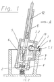
- Figur 1:
die Darstellung einer erfindungsgemäßen Schaltvorrichtung mit oberer Seilzuganbindung im Schnitt - Figur 2:
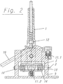
die Darstellung einer erfindungsgemäßen Schaltvorrichtung mit oberer Seilzuganbindung im Schnitt in der Ansicht entsprechend der Pfeilrichtung A nachFigur 1 - Figur 3:
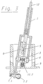
die Darstellung einer erfindungsgemäßen Schaltvorrichtung mit unterer Seilzuganbindung im Schnitt - Figur 4:
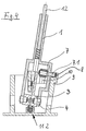
die Darstellung einer erfindungsgemäßen Schaltvorrichtung mit oberer Seilzuganbindung im Schnitt - Figur 5:
die Darstellung einer erfindungsgemäßen Schaltvorrichtung mit einer versetzten Seilzuganbindung im Schnitt. - Figur 6:
die Darstellung einer erfindungsgemäßen Schaltvorrichtung mit einer versetzten Seilzuganbindung im Schnitt in der Ansicht entsprechend der Pfeilrichtung B nachFigur 5.
- Figure 1:
the representation of a switching device according to the invention with an upper cable connection in section - Figure 2:
the representation of a switching device according to the invention with upper cable connection in section in the view corresponding to the direction of arrow A of Figure 1 - Figure 3:
the representation of a switching device according to the invention with lower cable connection in section - Figure 4:
the representation of a switching device according to the invention with an upper cable connection in section - Figure 5:
the representation of a switching device according to the invention with an offset cable connection in section. - Figure 6:
the representation of a switching device according to the invention with an offset cable connection in section in the view corresponding to the direction of arrow B of Figure 5.
In Figur 1 ist eine erfindungsgemäße Schaltvorrichtung für ein Automatikgetriebe eines Kraftfahrzeuges dargestellt. Diese weist einen Wählhebel (1) auf, an dessen oberer, dem Fahrzeugführer zugewandten Seite, sich ein Schaltknauf befindet. Dieser ist in Figur 1 zur Vereinfachung ebenso wie die Schaltkulisse, innerhalb der der Wählhebel geführt wird, nicht dargestellt.
Der Wählhebel (1) ist um eine Wählachse (2) schwenkbar in einem karosseriefesten Gehäuse (9) gelagert. Er ist in der Schrittschaltgasse darüber hinaus zusammen mit einem Wählhebelträger (3) um die Schaltachse (4) schwenkbar. Der Wählhebelträger weist entsprechend der vorgeschlagenen Lösung einen Arrettierungszapfen (5) auf, der in eine komplementäre Gehäuseausnehmung (6) einrückbar ist.
Der Arretierungszapfen (5) steht mit der Gehäuseausnehmung (6) in Eingriff, wenn sich der Wählhebel (1) in der Automatikschaltgasse befindet, sodaß der Wählhebelträger (3) an dem Gehäuse (9) festgelegt ist. Der Wählhebel wird dann in an sich bekannter Weise um die Schaltachse (4) verschwenkt. Die Anwahl der einzelnen Automatik-Fahrstufen ist somit möglich. Innerhalb des hohl ausgebildeten Wählhebels ist eine Zugstange (12) axial beweglich geführt. Diese stützt sich in dem Wählhebel unter Federkraft ab und ist innerhalb einer in das Gehäuse (9) eingearbeiteten Kontur, die den einzelnen Automatik-Fahrstufen entspricht, gleitend geführt.
Der Wählhebelträger (3) ist mit einem Radius versehen. Auf dieser Oberfläche gleitet die Zugstange (12) bereichsweise.
Um einen Wechsel von der Automatikschaltgasse in die Schrittschaltgasse vorzunehmen, wird der Wählhebel (1) seitwärts um die, im karosseriefesten Gehäuse (9) gelagerte Wählachse (2) verschwenkt. Dabei wird die Verbindung zwischen dem Arrettierungszapfen (5) des Wählhebelträgers (3) und der Gehäuseausnehmung (6) außer Eingriff gebracht. Der Wählhebel wird innnerhalb der Schrittschaltgasse ebenfalls um die Schaltachse (4) verschwenkt. Er stützt sich dabei bei der gezeigten Ausführung über einen Kugelzapfen (7) in dem Geäuse ab. Dieser Kugelzapfen dient dabei sowohl der Anbindung an ein Übertragungselement (10), welches seinerseits die Verbindung zwischen Schaltvorrichtung und Kraftfahrzeuggetriebe darstellt und in der dargestellten Ausführung ein Seilzug ist, als auch zur Lagerung und Abstützung des Wählhebels in dem Gehäuse (9). Die Anbindung des Kugelzapfens (7) an das Übertragungselement (10) erfolgt über eine an diesem Übertragungselement (10) befestigte Lagerschale, die vorzugsweise aus Kunststoff besteht und die Kugel (7.2) des Kugelzapfens (7) aufnimmt. Zur Lagerung und Abstützung des Wahlhebels in dem Gehäuse durchdringt der Kugelzapfen (7) mit seinem Zapfenende (7.1) den Wählhebel (1) und greift in eine komplementäre Lagerstelle (8) des Gehäuses (9) ein. Diese Lagerstelle ist mit einem begrenzt elastischen Kunststoff ausgekleidet.In Figure 1, a switching device according to the invention for an automatic transmission of a motor vehicle is shown. This has a selector lever (1), on the upper side of which, facing the driver, there is a gear knob. For simplification, this is not shown in FIG. 1, as is the shifting gate within which the selector lever is guided.
The selector lever (1) is mounted in a housing (9) fixed to the body and can be pivoted about a selector axis (2). It can also be swiveled around the switching axis (4) together with a selector lever bracket (3) in the stepping gate. In accordance with the proposed solution, the selector lever carrier has a locking pin (5) which can be inserted into a complementary housing recess (6).
The locking pin (5) engages with the housing recess (6) when the selector lever (1) is in the automatic shift gate, so that the selector lever carrier (3) is fixed to the housing (9). The selector lever is then pivoted in a manner known per se about the switching axis (4). It is therefore possible to select the individual automatic speed steps. A pull rod (12) is axially movably guided within the hollow selector lever. This is supported in the selector lever under spring force and is inside a contour worked into the housing (9), which corresponds to the individual automatic driving stages, is guided in a sliding manner.
The selector lever carrier (3) is provided with a radius. The pull rod (12) slides in regions on this surface.
In order to change from the automatic shift gate to the step shift gate, the selector lever (1) is pivoted sideways around the selector shaft (2) mounted in the body-fixed housing (9). The connection between the locking pin (5) of the selector lever carrier (3) and the housing recess (6) is disengaged. The selector lever is also pivoted around the switching axis (4) within the stepping gate. In the embodiment shown, it is supported in the housing via a ball pin (7). This ball pin serves both for the connection to a transmission element (10), which in turn represents the connection between the switching device and the motor vehicle transmission and in the embodiment shown is a cable pull, as well as for mounting and supporting the selector lever in the housing (9). The ball pin (7) is connected to the transmission element (10) via a bearing shell attached to this transmission element (10), which preferably consists of plastic and receives the ball (7.2) of the ball pin (7). For the storage and support of the selector lever in the housing, the ball pin (7) penetrates the selector lever (1) with its pin end (7.1) and engages in a complementary bearing (8) of the housing (9). This bearing point is lined with a limited elastic plastic.
Wie aus Figur 2 ersichtlich, ist erfindungsgemäß ein erstes Rastmittel (11.1) vorgesehen, das beim Verschwenken des Wählhebels (1) unter Federkraft auf diesen Wählhebel wirkt, sodaß nach Überwindung eines ![]()
Zur Simulierung des Schaltvorganges in der Schrittschaltgasse ist in dem Gehäuse (9) ein zweites Rastmittel (11.2) vorgesehen. Dieses Rastmittel erzeugt eine, der Bewegungsrichtung des Wählhebels entgegengesetze, Federkraft. Es erzeugt gewissermaßen nur einen Druckpunkt und drückt den Wählhebel zusätzlich in seine Ausgangsstellung innerhalb der Schrittschaltgasse zurück, soll aber keine echte Rastung darstellen, wie es bei dem ersten Rastmittel der Fall ist. Beide Rastmittel sind baugleich.
Die Wählachse (2) wird gemäß der in Figur 2 dargestellten Ausführungsform einer erfindungsgemäßen Schaltvorrichtung durch einen einfachen, in dem Gehäuse (9) gelagerten Bolzen (13) gebildet. Der Wahlhebelträger (3) stützt sich über den Bolzen (13) und Spiralfedern (14) in dem Gehäuse (9) ab und positioniert somit zugleich den Wählhebel. Die Zugstange (12) gleitet in der Kontur des Gehäuses (9), sowie bereichsweise auch auf dem Wählhebelträger (3).As can be seen from FIG. 2, a first latching means (11.1) is provided according to the invention, which acts on this selector lever under spring force when the selector lever (1) is pivoted, so that after overcoming one ![]()
A second locking device (11.2) is provided in the housing (9) to simulate the switching process in the stepping gate. This locking means generates a spring force opposite to the direction of movement of the selector lever. To a certain extent, it generates only one pressure point and additionally pushes the selector lever back into its starting position within the step shift gate, but is not intended to represent a real detent, as is the case with the first detent means. Both locking means are identical.
According to the embodiment of a switching device according to the invention shown in FIG. 2, the selection axis (2) is formed by a simple bolt (13) mounted in the housing (9). The selector lever carrier (3) is supported by the bolts (13) and Coil springs (14) in the housing (9) and thus positions the selector lever at the same time. The pull rod (12) slides in the contour of the housing (9) and in some areas also on the selector lever carrier (3).
In der Figur 3 ist eine erfindungsgemäße Schaltvorrichtung dargestellt, bei der die Anbindung des Übertragungselementes im unteren Bereich des Wählhebels erfolgt. Diese Bauform ist etwas schlanker, als die in den Figuren 1 bis 2 beschriebenen Ausführungen, erfordert jedoch in der Höhe mehr Bauraum.FIG. 3 shows a switching device according to the invention in which the transmission element is connected in the lower region of the selector lever. This design is somewhat slimmer than the designs described in FIGS. 1 to 2, but requires more installation space in terms of height.
Die Figur 4 zeigt eine Darstellung einer erfindungsgemäßen Schaltvorrichtung mit oberer Seilzuganbindung im Schnitt, wie sie ähnlich bereits der Figur 1 entnehmbar ist. Im Unterschied zu der Ausführungsform nach Figur 1 wird hier jedoch ein zylindrischer Zapfen (7) verwendet, der sowohl zur Anbindung des Übertragungselementes, als auch zur Lagerung und Abstützung des Wählhebels in dem Gehäuse (9) dient. Die Anbindung des Zapfens (7) an das Übertragungselement (10) erfolgt über eine an diesem Übertragungselement (10) befestigte Lagerschale, die aus elastischem, spielausgleichenden Kunststoff besteht und einen zylindrischen Bereich des Kugelzapfens (7) aufnimmt.FIG. 4 shows a sectional view of a switching device according to the invention with an upper cable pull connection, as can already be seen similar to FIG. 1. In contrast to the embodiment according to FIG. 1, however, a cylindrical pin (7) is used here, which is used both for connecting the transmission element and for storing and supporting the selector lever in the housing (9). The pin (7) is connected to the transmission element (10) via a bearing shell attached to this transmission element (10), which is made of elastic, play-compensating plastic and accommodates a cylindrical region of the ball pin (7).
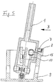
In Figur 5 ist eine erfindungsgemäße Schaltvorrichtung mit einer versetzten Seilzuganbindung im Schnitt dargestellt.
Dabei dient der zylindrische Zapfen (7) wie zuvor zur Lagerung und Abstützung des Wählhebels (1) in dem Gehäuse (9). Die Anbindung des Übertragungselementes (10) erfolgt über einen an dem Wählhebel (1) angeformten oder daran befestigten zweiten Zapfen (15). Dieser ist bei der dargestellten Lösung als Kugelzapfen ausgeführt. Die am Übertragungselement (10) befestigte Lagerschale nimmt die Kugel dieses Kugelzapfens (15) auf.In Figure 5, a switching device according to the invention with an offset cable connection is shown in section.
The cylindrical pin (7) serves, as before, for mounting and supporting the selector lever (1) in the housing (9). The transmission element (10) is connected by means of a second pin (15) which is molded onto the selector lever (1) or fastened thereon. In the solution shown, this is designed as a ball pin. The bearing shell attached to the transmission element (10) takes up the ball of this ball pin (15).
Figur 6 zeigt die bereits zu Figur 5 beschriebene Ausführung einer erfindungsgemäßen Schaltvorrichtung mit versetzter Seilzuganbindung im Schnitt, in der Ansicht entsprechend der Pfeilrichtung B nach Figur 5.FIG. 6 shows the embodiment of a switching device according to the invention with offset cable pull connection already described for FIG. 5 in section, in the view corresponding to the arrow direction B according to FIG. 5.
- 11
- WählhebelSelector lever
- 22nd
- WählachseDial axis
- 33rd
- WählhebelträgerSelector lever carrier
- 44th
- SchaltachseShift axis
- 55
- ArrettierungszapfenLocking pin
- 66
- GehäuseausnehmungHousing recess
- 77
- ZapfenCones
- 7.17.1
- ZapfenendeSpigot end
- 7.27.2
- KugelBullet
- 88th
- LagerstelleDepository
- 99
- Gehäusecasing
- 1010th
- ÜbertragungselementTransmission element
- 11.111.1
- RastmittelLocking means
- 11.211.2
- RastmittelLocking means
- 1212th
- Zugstangepull bar
- 1313
- Bolzenbolt
- 1414
- SpiralfederCoil spring
- 1515
- ZapfenCones
Claims (6)
dadurch gekennzeichnet, daß
das Übertragungselement (10) an einem zweiten, zu dem Zapfen (7) versetzt an dem Wählhebel (1) angeordneten Zapfen (15) befestigt ist.Switching device for an automatic transmission of a motor vehicle according to claim 1,
characterized in that
the transmission element (10) is fastened to a second pin (15) arranged on the selector lever (1) and offset from the pin (7).
dadurch gekennzeichnet, daß
der Zapfen (7) ein Kugelzapfen ist und dieser in der Schrittschaltgasse mit seinem Zapfenende (7.1) den Wählhebel (1) oberhalb der Schaltachse (4) durchgreift und in die in dem Gehäuse (9) gelegene Lagerstelle (8) eingreift, wobei an der Kugel (7.2) des Kugelzapfens (7) das Übertragungselement (10) angebracht ist.Switching device for an automatic transmission of a motor vehicle according to claim 1,
characterized in that
the pin (7) is a ball pin and this in the stepping gate with its pin end (7.1) passes through the selector lever (1) above the switching axis (4) and engages in the bearing (8) located in the housing (9), with the Ball (7.2) of the ball pin (7) the transmission element (10) is attached.
dadurch gekennzeichnet, daß
der Zapfen (7) ein Kugelzapfen ist und dieser in der Schrittschaltgasse mit seinem Zapfenende (7.1) den Wählhebel (1) unterhalb der Schaltachse (4) durchgreift und in die in dem Gehäuse (9) gelegene Lagerstelle (8) eingreift, wobei an der Kugel (7.2) des Kugelzapfens (7) das Übertragungselement (10) angebracht ist.Switching device for an automatic transmission of a motor vehicle according to claim 1,
characterized in that
the pin (7) is a ball pin and this in the stepping gate with its pin end (7.1) passes through the selector lever (1) below the switching axis (4) and engages in the bearing (8) located in the housing (9), whereby at the Ball (7.2) of the ball pin (7) the transmission element (10) is attached.
dadurch gekennzeichnet, daß
die Lagerstelle (8) des Gehäuses (9) mit einem begrenzt elastischen Kunststoff ausgekleidet ist.Switching device for an automatic transmission of a motor vehicle according to one of the preceding claims,
characterized in that
the bearing (8) of the housing (9) is lined with a limited elastic plastic.
dadurch gekennzeichnet, daß
Rastmittel (11.1) zur Festlegung des Wählhebels (1) in den jeweiligen Schaltgassen und darüber hinaus Rastmittel (11.2) zur Erzeugung eines Druckpunktes für den schrittweisen Schaltvorgang in der Schrittschaltgasse Verwendung finden.Switching device for an automatic transmission of a motor vehicle according to one or more of the preceding claims,
characterized in that
Latching means (11.1) for fixing the selector lever (1) in the respective shift gates and, in addition, latching means (11.2) for generating a pressure point for the step-by-step switching process in the stepping shift gate are used.
Applications Claiming Priority (2)
| Application Number | Priority Date | Filing Date | Title |
|---|---|---|---|
| DE19620515A DE19620515C2 (en) | 1996-05-22 | 1996-05-22 | Switching device for an automatic transmission of a motor vehicle |
| DE19620515 | 1996-05-22 |
Publications (3)
| Publication Number | Publication Date |
|---|---|
| EP0809046A2 true EP0809046A2 (en) | 1997-11-26 |
| EP0809046A3 EP0809046A3 (en) | 1998-11-04 |
| EP0809046B1 EP0809046B1 (en) | 2002-01-30 |
Family
ID=7794954
Family Applications (1)
| Application Number | Title | Priority Date | Filing Date |
|---|---|---|---|
| EP97108242A Expired - Lifetime EP0809046B1 (en) | 1996-05-22 | 1997-05-21 | Gear-shifting device for an automatic transmission of a motor vehicle |
Country Status (5)
| Country | Link |
|---|---|
| US (1) | US5884529A (en) |
| EP (1) | EP0809046B1 (en) |
| JP (1) | JP4067597B2 (en) |
| DE (1) | DE19620515C2 (en) |
| ES (1) | ES2170297T3 (en) |
Cited By (3)
| Publication number | Priority date | Publication date | Assignee | Title |
|---|---|---|---|---|
| WO2006056258A1 (en) * | 2004-11-24 | 2006-06-01 | Volkswagen Aktiengesellschaft | Shifting console of a motor vehicle transmission |
| CN101900201A (en) * | 2010-07-23 | 2010-12-01 | 重庆泰利福汽车零部件有限公司 | Vehicle automatic gear shifting device |
| CN103939596A (en) * | 2014-04-24 | 2014-07-23 | 法可赛(太仓)汽车配件有限公司 | Manual and automatic integrated electronic shifter assembly with LED indicating function |
Families Citing this family (12)
| Publication number | Priority date | Publication date | Assignee | Title |
|---|---|---|---|---|
| JPH11115525A (en) * | 1997-10-21 | 1999-04-27 | Tokai Rika Co Ltd | Shift lever device |
| SE512418C2 (en) * | 1998-06-29 | 2000-03-13 | Kongsberg Automotive Ab | Operating device |
| DE19853934B4 (en) * | 1998-11-23 | 2006-05-04 | ZF Lemförder Metallwaren AG | Switching device of a motor vehicle transmission |
| DE19937698C2 (en) * | 1999-08-10 | 2001-09-13 | Zf Lemfoerder Metallwaren Ag | Switching device of an automatic motor vehicle transmission |
| JP2001248716A (en) * | 2000-03-07 | 2001-09-14 | Honda Motor Co Ltd | Shift control device for vehicular automatic transmission |
| US6612194B2 (en) * | 2001-03-28 | 2003-09-02 | Grand Haven Stamped Products, Division Of Jsj Corporation | Shifter with load sensors for sensing shift demands |
| DE102005001818B4 (en) * | 2005-01-13 | 2006-11-30 | Zf Friedrichshafen Ag | Switching device for an automatic transmission of a motor vehicle |
| US20070166096A1 (en) * | 2005-06-03 | 2007-07-19 | Lim Chong K | Joint assembly |
| JP2010115955A (en) * | 2008-11-11 | 2010-05-27 | Tsuda Industries Co Ltd | Shift lever device |
| CN101439672B (en) * | 2008-12-23 | 2012-11-07 | 重庆长安汽车股份有限公司 | Automatic locating and unlocking device of gearshift |
| DE102014210126A1 (en) * | 2014-05-27 | 2015-12-03 | Zf Friedrichshafen Ag | A gear selector for an automatic transmission for a vehicle and method for operating a gear selector |
| KR101673781B1 (en) * | 2015-06-17 | 2016-11-07 | 현대자동차주식회사 | Vehicle transmission lever apparatus |
Citations (2)
| Publication number | Priority date | Publication date | Assignee | Title |
|---|---|---|---|---|
| DE4426207C1 (en) | 1994-07-23 | 1995-08-24 | Bayerische Motoren Werke Ag | Selector for automatic transmission of motor vehicle |
| DE19526059A1 (en) | 1995-07-17 | 1997-01-23 | Lemfoerder Metallwaren Ag | Switching device for automobile automatic transmission |
Family Cites Families (8)
| Publication number | Priority date | Publication date | Assignee | Title |
|---|---|---|---|---|
| DE3717675C5 (en) * | 1987-05-26 | 2005-12-15 | Bayerische Motoren Werke Ag | Switching device for a motor vehicle with automatic transmission |
| DE3927248C1 (en) * | 1989-08-18 | 1991-02-07 | Dr.Ing.H.C. F. Porsche Ag, 7000 Stuttgart, De | |
| US5044220A (en) * | 1988-03-10 | 1991-09-03 | Dr. Ing. H.C.F. Porsche Ag | Shifting arrangement for an automatic transmission of a motor vehicle |
| DE3927922C2 (en) * | 1988-03-10 | 1995-06-14 | Porsche Ag | Switching device for a motor vehicle transmission |
| US5070740A (en) * | 1988-03-10 | 1991-12-10 | Dr. Ing. H.C.F. Porsche Ag | Shifting arrangement for an automatic transmission of a motor vehicle |
| DE3927250A1 (en) * | 1989-08-18 | 1991-02-21 | Porsche Ag | SWITCHING DEVICE |
| DE4217773A1 (en) * | 1992-05-29 | 1993-12-02 | Audi Ag | Vehicle automatic gearbox selector - has conventional arrangement of manual gears and electronic control unit for gear changing in DRIVE position |
| FR2705129B1 (en) * | 1993-05-11 | 1995-08-11 | Peugeot | Gear control device for an automatic vehicle gearbox. |
-
1996
- 1996-05-22 DE DE19620515A patent/DE19620515C2/en not_active Expired - Fee Related
-
1997
- 1997-05-19 JP JP12773397A patent/JP4067597B2/en not_active Expired - Fee Related
- 1997-05-21 ES ES97108242T patent/ES2170297T3/en not_active Expired - Lifetime
- 1997-05-21 US US08/861,360 patent/US5884529A/en not_active Expired - Lifetime
- 1997-05-21 EP EP97108242A patent/EP0809046B1/en not_active Expired - Lifetime
Patent Citations (2)
| Publication number | Priority date | Publication date | Assignee | Title |
|---|---|---|---|---|
| DE4426207C1 (en) | 1994-07-23 | 1995-08-24 | Bayerische Motoren Werke Ag | Selector for automatic transmission of motor vehicle |
| DE19526059A1 (en) | 1995-07-17 | 1997-01-23 | Lemfoerder Metallwaren Ag | Switching device for automobile automatic transmission |
Cited By (5)
| Publication number | Priority date | Publication date | Assignee | Title |
|---|---|---|---|---|
| WO2006056258A1 (en) * | 2004-11-24 | 2006-06-01 | Volkswagen Aktiengesellschaft | Shifting console of a motor vehicle transmission |
| CN101900201A (en) * | 2010-07-23 | 2010-12-01 | 重庆泰利福汽车零部件有限公司 | Vehicle automatic gear shifting device |
| CN101900201B (en) * | 2010-07-23 | 2013-06-19 | 重庆泰利福汽车零部件有限公司 | Vehicle automatic gear shifting device |
| CN103939596A (en) * | 2014-04-24 | 2014-07-23 | 法可赛(太仓)汽车配件有限公司 | Manual and automatic integrated electronic shifter assembly with LED indicating function |
| CN103939596B (en) * | 2014-04-24 | 2016-11-16 | 法可赛(太仓)汽车配件有限公司 | Auto-manual electronic selector assembly with LED instruction function |
Also Published As
| Publication number | Publication date |
|---|---|
| DE19620515C2 (en) | 1998-04-30 |
| EP0809046B1 (en) | 2002-01-30 |
| JPH1067248A (en) | 1998-03-10 |
| JP4067597B2 (en) | 2008-03-26 |
| EP0809046A3 (en) | 1998-11-04 |
| DE19620515A1 (en) | 1997-11-27 |
| US5884529A (en) | 1999-03-23 |
| ES2170297T3 (en) | 2002-08-01 |
Similar Documents
| Publication | Publication Date | Title |
|---|---|---|
| DE19526059C2 (en) | Switching device for an automatic transmission of a motor vehicle | |
| EP0794362B1 (en) | Gear selector for a transmission | |
| EP0693391B1 (en) | Gear selection apparatus for an automatic transmission of a motor vehicle | |
| EP0809046B1 (en) | Gear-shifting device for an automatic transmission of a motor vehicle | |
| DE102005062167B3 (en) | Gearshift lever with actuating device for reverse gear lock, has selecting finger is arranged at curvature of exhibiting gearshift lever having curvature, which rises in axis of bell crank lever and cooperate with it | |
| EP0784168B1 (en) | Shift arrangement for automatic transmission of a motor vehicle | |
| EP1836414A1 (en) | Shifting device for an automatic gearbox of a motor vehicle | |
| DE4100574A1 (en) | JOINT BETWEEN A GEARBOX AND ITS GEAR SHIFTING MECHANISM WITH REMOTE CONTROL | |
| EP0837266B1 (en) | Selecting device for an automatic transmission of a vehicle | |
| EP0825364B1 (en) | Shift selector for automatic vehicle transmission | |
| EP0699853A1 (en) | Mechanism for transmitting movement of vehicle gear selector | |
| DE19913835C2 (en) | Switching device for motor vehicles | |
| EP1531290B1 (en) | Gear selector device | |
| EP1267240A1 (en) | Gear change device for a manual transmission of a motor vehicle | |
| DE19620532A1 (en) | Gear-changing system for automatic transmission of motor vehicle with two-part change lever | |
| EP0913604A1 (en) | Leaf spring biased detent for a change-speed gearbox | |
| DE19632736C2 (en) | Switching device for the automatic transmission of a motor vehicle | |
| DE19740176C2 (en) | Manual switching device for a motor vehicle | |
| DE10041926A1 (en) | Gear selector grip for automatic motor vehicle transmissions has press button acing directly on joint to operate selector bar inside selector lever | |
| DE2909458A1 (en) | Two-position motor vehicle gear shift lever - is located in one or another position by bistable compression spring | |
| DE19600525C1 (en) | Switchgear for vehicle's automatic gear | |
| DE102004033672B4 (en) | Switching device for an automatic transmission | |
| DE3518118A1 (en) | Transmission remote control for motor vehicles |
Legal Events
| Date | Code | Title | Description |
|---|---|---|---|
| PUAI | Public reference made under article 153(3) epc to a published international application that has entered the european phase |
Free format text: ORIGINAL CODE: 0009012 |
|
| AK | Designated contracting states |
Kind code of ref document: A2 Designated state(s): ES FR GB IT SE |
|
| PUAL | Search report despatched |
Free format text: ORIGINAL CODE: 0009013 |
|
| AK | Designated contracting states |
Kind code of ref document: A3 Designated state(s): ES FR GB IT SE |
|
| 17P | Request for examination filed |
Effective date: 19981008 |
|
| RAP1 | Party data changed (applicant data changed or rights of an application transferred) |
Owner name: ZF LEMFOERDER METALLWAREN AG |
|
| GRAG | Despatch of communication of intention to grant |
Free format text: ORIGINAL CODE: EPIDOS AGRA |
|
| GRAG | Despatch of communication of intention to grant |
Free format text: ORIGINAL CODE: EPIDOS AGRA |
|
| GRAH | Despatch of communication of intention to grant a patent |
Free format text: ORIGINAL CODE: EPIDOS IGRA |
|
| 17Q | First examination report despatched |
Effective date: 20010625 |
|
| GRAH | Despatch of communication of intention to grant a patent |
Free format text: ORIGINAL CODE: EPIDOS IGRA |
|
| GRAA | (expected) grant |
Free format text: ORIGINAL CODE: 0009210 |
|
| REG | Reference to a national code |
Ref country code: GB Ref legal event code: IF02 |
|
| AK | Designated contracting states |
Kind code of ref document: B1 Designated state(s): ES FR GB IT SE |
|
| GBT | Gb: translation of ep patent filed (gb section 77(6)(a)/1977) |
Effective date: 20020407 |
|
| ET | Fr: translation filed | ||
| REG | Reference to a national code |
Ref country code: ES Ref legal event code: FG2A Ref document number: 2170297 Country of ref document: ES Kind code of ref document: T3 |
|
| PLBE | No opposition filed within time limit |
Free format text: ORIGINAL CODE: 0009261 |
|
| STAA | Information on the status of an ep patent application or granted ep patent |
Free format text: STATUS: NO OPPOSITION FILED WITHIN TIME LIMIT |
|
| 26N | No opposition filed | ||
| PGFP | Annual fee paid to national office [announced via postgrant information from national office to epo] |
Ref country code: GB Payment date: 20100329 Year of fee payment: 14 |
|
| PGFP | Annual fee paid to national office [announced via postgrant information from national office to epo] |
Ref country code: ES Payment date: 20100611 Year of fee payment: 14 |
|
| PGFP | Annual fee paid to national office [announced via postgrant information from national office to epo] |
Ref country code: SE Payment date: 20110512 Year of fee payment: 15 |
|
| GBPC | Gb: european patent ceased through non-payment of renewal fee |
Effective date: 20110521 |
|
| PG25 | Lapsed in a contracting state [announced via postgrant information from national office to epo] |
Ref country code: GB Free format text: LAPSE BECAUSE OF NON-PAYMENT OF DUE FEES Effective date: 20110521 |
|
| REG | Reference to a national code |
Ref country code: ES Ref legal event code: FD2A Effective date: 20120717 |
|
| PG25 | Lapsed in a contracting state [announced via postgrant information from national office to epo] |
Ref country code: ES Free format text: LAPSE BECAUSE OF NON-PAYMENT OF DUE FEES Effective date: 20110522 |
|
| PGFP | Annual fee paid to national office [announced via postgrant information from national office to epo] |
Ref country code: FR Payment date: 20120608 Year of fee payment: 16 |
|
| PGFP | Annual fee paid to national office [announced via postgrant information from national office to epo] |
Ref country code: IT Payment date: 20120519 Year of fee payment: 16 |
|
| REG | Reference to a national code |
Ref country code: SE Ref legal event code: EUG |
|
| PG25 | Lapsed in a contracting state [announced via postgrant information from national office to epo] |
Ref country code: SE Free format text: LAPSE BECAUSE OF NON-PAYMENT OF DUE FEES Effective date: 20120522 |
|
| PG25 | Lapsed in a contracting state [announced via postgrant information from national office to epo] |
Ref country code: IT Free format text: LAPSE BECAUSE OF NON-PAYMENT OF DUE FEES Effective date: 20130521 |
|
| REG | Reference to a national code |
Ref country code: FR Ref legal event code: ST Effective date: 20140131 |
|
| PG25 | Lapsed in a contracting state [announced via postgrant information from national office to epo] |
Ref country code: FR Free format text: LAPSE BECAUSE OF NON-PAYMENT OF DUE FEES Effective date: 20130531 |