EP0808970A2 - Cylinder lock - Google Patents
Cylinder lock Download PDFInfo
- Publication number
- EP0808970A2 EP0808970A2 EP96118819A EP96118819A EP0808970A2 EP 0808970 A2 EP0808970 A2 EP 0808970A2 EP 96118819 A EP96118819 A EP 96118819A EP 96118819 A EP96118819 A EP 96118819A EP 0808970 A2 EP0808970 A2 EP 0808970A2
- Authority
- EP
- European Patent Office
- Prior art keywords
- cylinder
- plug
- lock according
- cylinder lock
- cylinder core
- Prior art date
- Legal status (The legal status is an assumption and is not a legal conclusion. Google has not performed a legal analysis and makes no representation as to the accuracy of the status listed.)
- Granted
Links
- 229910000831 Steel Inorganic materials 0.000 claims description 38
- 239000010959 steel Substances 0.000 claims description 38
- 239000007787 solid Substances 0.000 claims description 26
- 230000001681 protective effect Effects 0.000 claims description 23
- 239000000463 material Substances 0.000 claims description 15
- 230000004323 axial length Effects 0.000 claims description 8
- 239000010935 stainless steel Substances 0.000 claims description 5
- 229910001220 stainless steel Inorganic materials 0.000 claims description 5
- KUNSUQLRTQLHQQ-UHFFFAOYSA-N copper tin Chemical class [Cu].[Sn] KUNSUQLRTQLHQQ-UHFFFAOYSA-N 0.000 claims description 4
- 229910052750 molybdenum Inorganic materials 0.000 claims description 4
- 229910052804 chromium Inorganic materials 0.000 claims description 3
- 238000005516 engineering process Methods 0.000 claims description 3
- 230000003313 weakening effect Effects 0.000 claims description 3
- 239000000853 adhesive Substances 0.000 claims description 2
- 230000001070 adhesive effect Effects 0.000 claims description 2
- 238000006243 chemical reaction Methods 0.000 claims description 2
- 239000000203 mixture Substances 0.000 claims 2
- 229910045601 alloy Inorganic materials 0.000 claims 1
- 239000000956 alloy Substances 0.000 claims 1
- 238000010276 construction Methods 0.000 claims 1
- 230000000704 physical effect Effects 0.000 claims 1
- 235000019589 hardness Nutrition 0.000 description 6
- 229910000906 Bronze Inorganic materials 0.000 description 4
- 229910052759 nickel Inorganic materials 0.000 description 4
- 239000010974 bronze Substances 0.000 description 3
- 229910052751 metal Inorganic materials 0.000 description 3
- 239000002184 metal Substances 0.000 description 3
- 229910001369 Brass Inorganic materials 0.000 description 2
- 239000010951 brass Substances 0.000 description 2
- 230000000694 effects Effects 0.000 description 2
- 238000010521 absorption reaction Methods 0.000 description 1
- 230000006835 compression Effects 0.000 description 1
- 238000007906 compression Methods 0.000 description 1
- 238000005553 drilling Methods 0.000 description 1
- 238000002474 experimental method Methods 0.000 description 1
- 239000002360 explosive Substances 0.000 description 1
- 238000009434 installation Methods 0.000 description 1
- 229910000734 martensite Inorganic materials 0.000 description 1
- 150000002739 metals Chemical class 0.000 description 1
- 238000000034 method Methods 0.000 description 1
- 230000009467 reduction Effects 0.000 description 1
- 238000005096 rolling process Methods 0.000 description 1
- 229910052721 tungsten Inorganic materials 0.000 description 1
- 239000010937 tungsten Substances 0.000 description 1
- -1 tungsten carbides Chemical class 0.000 description 1
Images






Classifications
-
- E—FIXED CONSTRUCTIONS
- E05—LOCKS; KEYS; WINDOW OR DOOR FITTINGS; SAFES
- E05B—LOCKS; ACCESSORIES THEREFOR; HANDCUFFS
- E05B17/00—Accessories in connection with locks
- E05B17/20—Means independent of the locking mechanism for preventing unauthorised opening, e.g. for securing the bolt in the fastening position
- E05B17/2084—Means to prevent forced opening by attack, tampering or jimmying
-
- E—FIXED CONSTRUCTIONS
- E05—LOCKS; KEYS; WINDOW OR DOOR FITTINGS; SAFES
- E05B—LOCKS; ACCESSORIES THEREFOR; HANDCUFFS
- E05B27/00—Cylinder locks or other locks with tumbler pins or balls that are set by pushing the key in
-
- E—FIXED CONSTRUCTIONS
- E05—LOCKS; KEYS; WINDOW OR DOOR FITTINGS; SAFES
- E05B—LOCKS; ACCESSORIES THEREFOR; HANDCUFFS
- E05B17/00—Accessories in connection with locks
- E05B17/0054—Fraction or shear lines; Slip-clutches, resilient parts or the like for preventing damage when forced or slammed
- E05B17/0062—Fraction or shear lines; Slip-clutches, resilient parts or the like for preventing damage when forced or slammed with destructive disengagement
Definitions
- the invention relates to a cylinder lock, in particular for use on protective devices and traps for slot machines and vending machines, on lattice rolling gates, on movable protective grilles or the like, with a cylinder housing in which a with a cylinder core with a key channel running in the direction of the axis in one on both ends of the Cylinder housing opening opening is rotatably arranged, which can be rotated by a limited amount in the circumferential direction by a flat key to be inserted into the key channel, with several rows of cased and / or adjacent housing pins and associated core pins that form pin tumblers, and with a slide bolt that can be driven by the cylinder core , wherein the plug cylinder lock is arranged in at least one receiving opening of the object to be secured and locked there.
- Mortise cylinder locks of the required type are known through a variety of designs. These plug-in cylinder locks, however, are relatively easy and quick to break open, despite the arrangement of numerous housing and core pins, for example by screwing a screw into the key channel, by means of which the cylinder core can be pulled out of the cylinder housing. The pin tumblers are sheared off, the slide bolt is bent and torn off and also torn out of the housing.
- the invention has for its object to make a plug-in cylinder lock of the required type much more burglar-proof.
- the outer jacket of the cylinder housing is deformed in the event of a break-in and the walls in the region of the end-face bore are pressed inwards.
- the slide bolt is either sheared off or bent so far that it can be torn out of the opening of the object to be protected relatively easily. The whole lock can then be pulled out of the opening.
- the explosive forces that occur are approximately uniformly transmitted to the wall of the bore and thus to the cylinder jacket, with such large forces that the cylinder is destroyed and the slide bolt torn off and sheared off even under the given conditions with the strongest wall design becomes. It must be taken into account that in the case of protective devices and traps for gaming machines and vending machines or the like, the installation conditions are determined. In particular, the distance fixed between the slide bolt and an inner wall of the object to be protected and cannot be enlarged as desired, so that one is very limited in the area of the inner end section of the plug-in cylinder with regard to constructive measures.
- the result of the invention is that the high deformation forces which occur and which are transmitted to the inner end section of the cylinder housing in the event of a break-in are evenly absorbed by the support disk.
- the support disc prevents deformation of the cylinder housing.
- a tensile force applied to the plug-in cylinder lock in the longitudinal axis direction can deform the slide bolt. Characterized in that a tangential surface is present at the end inner end of the cylinder housing, it is achieved that the slide bolt can lay down and be supported on this surface, so that in the further course of the attempt to break open the slide bolt acts like a wedge in the receiving opening for the plug-in cylinder , that is, the cylinder lock cannot be pulled out of the opening of the object.
- the support disk is supported on its circumference evenly on all sides on a shape-matched inner wall of the cylinder housing.
- the support disk is arranged with a press fit in the opening of the cylinder housing.
- the support disc is screwed into a thread of the receiving opening.
- the support disc is glued in, while it is soldered in the embodiment according to claim 6 and welded in the embodiment according to claim 7 .
- the cylinder housing is provided with a plurality of steps or shoulders into which a form-adapted support body in the form of a disc engages, so that this not only stiffens and supports the cylinder housing radially but also axially in this area - Claim 8 .
- the support disc is arranged in an arranged at the inner end of the cylinder housing, enlarged in diameter of the cylinder housing.
- the support disc consists of armored steel weapon technology, for example as it is used for the casing of battle tanks.
- the support disc can also consist of a very hard, high-tempered special steel, in particular armored steel.
- Such steels can be, for example, martinsite-hardenable steels.
- a martinsite-hardening steel can have the following characteristics: Stretch limit 800 to 1000 N / mm 2 strength 1100 to 1300 N / mm 2 Elongation at break 15% Constriction 7 to 15% hardness 350 HB
- Such a martensitic steel can for example 5.0% Mo 18.0% Ni 10.0% Co 1.0% Ti 4-6% Mon 16-19% Ni 7-11% Co 0.3-1.5% Ti or for example 8 to 13% Cr, preferably 8.7 to 9.3% Cr 7.8 to 11% Ni, preferably 8.3 to 10.2% Ni 4.5 to 1% Mo, preferably 2.9 to 1.9% Mo 1.9 to 3.2% Co, preferably 2.0 to 3.1% Co 0.5 to 1.9% Ti, preferably 0.8% Ti exhibit.
- martinsite-hardenable steels are relatively tough and easy to deform in the solution-annealed condition, they are extremely hard in the heat-hardened condition. Such hardnesses can optionally be used for the support disks.
- sheet metal with extremely high hardness is normally limited due to the lack of weldability, but this does not matter here.
- the support disk is made of bronze.
- Bronze has a high pressure absorption capacity, does not burst as easily under pressure and does not deform as for example certain types of steel - claim 11 .
- CuSn8 is used as the material for the support disk.
- the material has at least a tensile strength of 390 to 750 N / mm 2 , preferably 690 N / mm 2 , a 0.2% proof stress of 290 to 700, preferably 640 N / mm 2 , an elongation at break from 60 to 10, preferably 10, and a Brinell hardness HB from 90 to 250, preferably 220.
- Claim 13 describes an advantageous embodiment.
- the protective cover arranged at the end face and facing outwards has a special shape, by means of which the cylinder core is further secured against being pulled outwards.
- the protective hood radially supports the outward-facing end region of the cylinder core.
- a cylinder core head is connected to the actual cylinder core by a predetermined breaking point, which occurs when an attempt is made to break in predetermined load is separable. In this way it is prevented that only predetermined forces can be transmitted to the storage for the plug-in cylinder lock in the event of a break-in attempt.
- Solid carbide pins prevent a pulling screw from being screwed into the cylinder core, for example. After a short distance, this hits a solid carbide pin and is deflected by it, so that the cutting edges of the drawing screw become blunt and cannot penetrate further into the material of the cylinder core.
- Claim 33 describes a special, inventive solution for the arrangement of solid carbide pins, which also applies to claim 34 .
- Claim 35 describes a further embodiment, in which the cylinder core head is coupled to the actual cylinder core by an adhesive connection, which can be separated when a predetermined load is exceeded.
- the cylinder core head is coupled to the cylinder core via a plurality of pins or screws which also tear off when a defined shear and / or tensile stress is exceeded.
- the predetermined breaking point is formed in the inventive solution according to claim 37 by weakening the cylinder core at a certain point. This weakening is formed by several radially directed recesses, for example bores. At this point, a predetermined breaking point is produced in this way, at which the cylinder core head can be separated from the cylinder core in a defined manner.
- the cylinder lock shown in the drawing has a cylinder housing 1 and a cylinder core 2 rotatably arranged therein in a bore, which has a longitudinally extending key channel 3, into which a flat key, not shown, can be inserted.
- the flat key can be designed as a longitudinal rib profile flat key and have a plurality of depressions through which it controls core pins 4, 5, 6, 7 and 8, which are arranged in the longitudinal axis direction of the cylinder core 2 and are parallel to one another in the blind bores of the cylinder core 2 and which are longitudinally displaceable Flat key facing ends are tapered (Fig. 5, 7).
- Housing pins 9, 10, 11, 12 and 13 are arranged coaxially to the core pins 4, 5, 6, 7 and 8 and are displaceable in bores of the cylinder housing 1 running parallel to one another.
- the housing pins 9 to 13 are each supported against the restoring force of compression springs, which are only indicated schematically in the drawing and which are each supported against the end face of the relevant housing pin 9 to 13 facing away from the associated core pin 4 to 8, so that the Core pins 4 to 8 are spring-loaded accordingly.
- the core pins 4 to 8 and the housing pins 9 to 13 form the pin tumblers of the cylinder lock.
- the thickness F measured in the axial direction is less than the axial length E of the opening 15 of the cylinder housing section 14.
- the screw 19 connects a slide bolt 21 to the cylinder core 2 in a gearbox manner.
- This slide bolt 21 emerges from a slot-shaped recess 22 of the cylinder housing 1 which extends circumferentially over a circular sector.
- the movement of the cylinder core 2 is limited by a stop pin 23 which, on the one hand, engages in a radial slot 24, which extends approximately by 90 degrees or another angle in the circumferential direction of the cylinder core 2 and, on the other hand, is arranged in a through bore 25 of the cylinder housing 1.
- the head of the stop pin 23 engages in a bore 26 which is arranged in a steel jacket sleeve 27 which encloses the cylinder housing 1 over most of its length.
- the protective hood 28 is connected to the steel jacket sleeve 27 and to the cylinder housing 1 by a plurality of radial pins 30 distributed over the circumference, which end at the outer periphery of the length section 29.
- a locking pin is arranged which engages in a slot 32 of a wall 33.
- the slot 32 extends in the axial longitudinal direction of the cylinder lock. Via this locking pin 31, the reaction forces which are transmitted to the plug-in cylinder lock via the flat key can be absorbed, so that the plug-in cylinder lock cannot twist.
- a further radial pin is arranged, which extends through a through bore 35 of the steel jacket sleeve 27 and engages in a blind bore 36 arranged coaxially thereto, which is arranged in the cylinder housing 1.
- walls of an object to be protected for example a slot machine, are indicated.
- the walls 33, 37 and 38 each have a through hole which are arranged coaxially to one another and into which the cylinder lock is inserted.
- the dimension X is generally fixed in slot machines, so that the distance between the end face 40 and the inside 41 of the wall 39 is generally small. Due to the fact that the dimension X is given constructively, there is normally little possibility of constructive design.
- the cylinder housing section 14 is provided on its diametrically opposite side with the locking position of the slide bolt 21 with a tangentially arranged surface 42 running in the direction of the axis of the cylinder housing 1, against which the slide bolt 21 is supported, placed on and supported during an attempted break-in can wedge if necessary.
- the design of the slide bolt 21 can be seen more clearly. From this it can be seen that the slide bolt 21 has a slot 43 which opens out laterally and into which the screw head 18 acts as an eccentric drive intervenes. The slide bolt 21 is guided through a radial groove. The slide bolt 21 is rounded on its top and bottom in each case according to a circular arc 44 or 45.
- the slide bolt 21 consists of stainless steel, for example X 5 CrNi 18 10, material number 1.4301.
- a steel is an austenitic steel which, when quenched, has the following properties at room temperature:
- the protective cover 28 has, in terms of material, integrally connected to it, radially directed sectors 46 or 47 or radial sectors, which face 48 facing outwards Cylinder core 2 overlap on part of its surface. In this way, the cylinder core 2 is still secured against axial pulling out.
- radial sectors 46 and 47 extend right up to the key channel 3, so that manipulations with intrusion tools are made more difficult.
- FIGS. 13 to 25 For the embodiment shown in FIGS. 13 to 25, the same reference numerals have been used for parts with the same function as in the embodiment according to FIGS. 1 to 12.
- the operation of the embodiment according to FIGS. 13 to 25 thus corresponds fundamentally to the embodiment according to FIGS. 1 to 12, so that with regard to the basic structure and the operation of the plug-in cylinder lock, those made in connection with the embodiment according to FIGS. 1 to 12 Executions can be referenced.
- FIGS. 13 to 25 differs from the previously described embodiment as follows:
- the protective hood 28 is no longer provided with radial sectors 46, as in the embodiment according to FIGS. 1 to 12. Rather, the cylinder core 2 is provided at its outwardly facing end section with a cylinder core head 49 which is enlarged in diameter in the embodiment shown and which is integrally connected to the cylinder core 2 via a predetermined breaking point 50. If necessary, the cylinder core head 49 can also have the same diameter as the cylinder core 2.
- the predetermined breaking point 50 is formed by strip-shaped material parts present on both sides of the key channel 3, which in the exemplary embodiment shown is delimited outwards by walls 51 and 52 arranged parallel to one another and arranged symmetrically to the axis of rotation of the cylinder core 2.
- these walls 51, 52 are each formed by a radial groove 53 or 54.
- the axial width G can be 0.5 mm for each radial groove 53 or 54 in one embodiment.
- Both grooves 53 and 54 are of the same size and are arranged symmetrically to the longitudinal axis.
- the axial length H of the cylinder core head 49 is 6 mm in this embodiment, while the grooves 53 and 54 are arranged approximately at an axial distance of approximately the groove width G behind the cylinder core head 49.
- the design of the predetermined breaking point 50 can also be different
- predetermined breaking point 50 it is possible to provide more than two grooves.
- grooves 53 and 54 it is also possible to produce the predetermined breaking point 50 differently, for example by means of several bores which run parallel or at an angle to one another or by other cross-sectional reductions in the area of the predetermined breaking point or by using different materials for the cylinder core 2 and the cylinder core head 49.
- the cylinder core head 49 is provided next to the longitudinal center axis (axis of rotation) of the cylinder core 2 with a solid carbide pin 56 which is thus orthogonal to the axis of rotation of the cylinder core 2 and which is on the outer cylindrical surface of the cylinder core head 49 ends.
- the cylinder core 2 in the embodiment shown is provided on each side of its axis of rotation with a further solid carbide pin 57 and 58, respectively.
- these solid carbide pins 57, 58 can have the same dimensions, at least in diameter, as the solid carbide pin 56.
- the solid carbide pins 57 and 58 also each end on the outer cylindrical surface of the cylinder core 2, so that its rotation is not hindered.
- a hard metal not only hardened steels but also tungsten carbides and other well-known hard metals come into consideration.
- a pulling screw 55 is now screwed into the key channel 3, it is first deflected from its longitudinal axis by the solid carbide pin 56 (FIG. 25) and then either meets the solid carbide pin 57 or 58, and can therefore only over a small part of its length Key channel 3 - if at all - are screwed in so that the intended full pulling loads cannot be transferred to the cylinder core 2.
- the screw-in test thus generally ends at the solid carbide pin 57, so that only the cylinder core head 49 can be torn off at the predetermined breaking point 50.
- the cutting tips of the drawing screw 55 become blunt when screwed in by the solid carbide pin 56, so that they can no longer be screwed into the cylinder core head 49, which is usually made of brass, and the cylinder core 2, which is also made of brass. If a new pull screw 55 were used which does not yet have blunt cutting tips, this will hit in any case on the solid carbide pin 57 and can then also no longer be screwed in.
Landscapes
- Control Of Vending Devices And Auxiliary Devices For Vending Devices (AREA)
- Vehicle Body Suspensions (AREA)
- Chairs Characterized By Structure (AREA)
- Valve Device For Special Equipments (AREA)
- Connector Housings Or Holding Contact Members (AREA)
- Filling Or Discharging Of Gas Storage Vessels (AREA)
- Storage Of Web-Like Or Filamentary Materials (AREA)
Abstract
Description
Die Erfindung betrifft ein Steckzylinderschloß, insbesondere zur Verwendung an Schutzvorrichtungen und Fallen für Spiel- und Warenautomaten, an Gitterrolltoren, an beweglichen Schutzgittern oder dergleichen, mit einem Zylindergehäuse, in dem ein mit einem Zylinderkern mit einem in Lächsachsrichtung verlaufenden Schlüsselkanal in einer an beiden Stirnseiten des Zylindergehäuses ausmündenden Öffnung drehbar angeordnet ist, der durch einen in den Schlüsselkanal einzuführenden Flachschlüssel um ein begrenztes Maß in Umfangsrichtung drehantreibbar ist, mit mehreren Reihen hinter- und/oder nebeneinanderliegenden Gehäusestiften und zugeordneten Kernstiften, die Stiftzuhaltungen bilden, und mit einem von dem Zylinderkern antreibbaren Schubriegel, wobei das Steckzylinderschloß in mindestens einer Aufnahmeöffnung des zu sichernden Objektes angeordnet und dort arretiert ist.The invention relates to a cylinder lock, in particular for use on protective devices and traps for slot machines and vending machines, on lattice rolling gates, on movable protective grilles or the like, with a cylinder housing in which a with a cylinder core with a key channel running in the direction of the axis in one on both ends of the Cylinder housing opening opening is rotatably arranged, which can be rotated by a limited amount in the circumferential direction by a flat key to be inserted into the key channel, with several rows of cased and / or adjacent housing pins and associated core pins that form pin tumblers, and with a slide bolt that can be driven by the cylinder core , wherein the plug cylinder lock is arranged in at least one receiving opening of the object to be secured and locked there.
Steckzylinderschlösser der vorausgesetzten Gattung sind durch vielfältige Konstruktionen vorbekannt. Diese Steckzylinderschlösser sind allerdings durch Einbruch trotz Anordnung zahlreicher Gehäuse- und Kernstifte relativ einfach und schnell aufzubrechen, und zwar zum Beispiel dadurch, daß in den Schlüsselkanal eine Schraube hineingedreht wird, mittels derer sich der Zylinderkern aus dem Zylindergehäuse herausziehen läßt. Dabei werden die Stiftzuhaltungen abgeschert, der Schubriegel verbogen und abgerissen und ebenfalls aus dem Gehäuse herausgerissen.Mortise cylinder locks of the required type are known through a variety of designs. These plug-in cylinder locks, however, are relatively easy and quick to break open, despite the arrangement of numerous housing and core pins, for example by screwing a screw into the key channel, by means of which the cylinder core can be pulled out of the cylinder housing. The pin tumblers are sheared off, the slide bolt is bent and torn off and also torn out of the housing.
Der Erfindung liegt die Aufgabe zugrunde, ein Steckzylinderschloß der vorausgesetzten Gattung wesentlich einbruchssicherer zu machen.The invention has for its object to make a plug-in cylinder lock of the required type much more burglar-proof.
Die Aufgabe wird durch die in Patentanspruch 1 wiedergegebenen Merkmale gelöst.The object is achieved by the features set out in
Beim Stand der Technik wird bei einem Einbruch der äußere Mantel des Zylindergehäuses deformiert und die Wandungen im Bereich der endstirnseitigen Bohrung nach innen gedrückt. Dabei wird auch der Schubriegel entweder abgeschert oder soweit umgebogen, daß er relativ problemlos aus der Öffnung des zu schützenden Objektes herausgerissen werden kann. Das ganze Schloß läßt sich danach aus der Öffnung herausziehen. Versuche der Anmelderin haben dabei gezeigt, daß die auftretenden Sprengkräfte sich annähernd gleichförmig auf die Wandung der Bohrung und damit auf den Zylindermantel übertragen, wobei so große Kräfte auftreten, daß auch unter den gegebenen Verhältnissen bei stärkster Wandausführung der Zylinder zerstört und der Schubriegel abgerissen und abgeschert wird. Berücksichtigt werden muß dabei, daß bei Schutzvorrichtungen und Fallen für Spiel- und Warenautomaten oder dergleichen die Einbauverhältnisse festlegen. Insbesondere ist der Abstand zwischen Schubriegel und einer inneren Wandung des zu schützenden Objektes festliegend und kann nicht beliebig vergrößert werden, so daß man im Bereich des inneren Endabschnittes des Steckzylinders hinsichtlich konstruktiver Maßnahmen sehr eingeschränkt ist.In the prior art, the outer jacket of the cylinder housing is deformed in the event of a break-in and the walls in the region of the end-face bore are pressed inwards. The slide bolt is either sheared off or bent so far that it can be torn out of the opening of the object to be protected relatively easily. The whole lock can then be pulled out of the opening. Experiments by the applicant have shown that the explosive forces that occur are approximately uniformly transmitted to the wall of the bore and thus to the cylinder jacket, with such large forces that the cylinder is destroyed and the slide bolt torn off and sheared off even under the given conditions with the strongest wall design becomes. It must be taken into account that in the case of protective devices and traps for gaming machines and vending machines or the like, the installation conditions are determined. In particular, the distance fixed between the slide bolt and an inner wall of the object to be protected and cannot be enlarged as desired, so that one is very limited in the area of the inner end section of the plug-in cylinder with regard to constructive measures.
Durch die Erfindung wird erreicht, daß die auftretenden hohen Deformationskräfte, die bei einem Einbruch auf den inneren Endabschnitt des Zylindergehäuses übertragen von der Stützscheibe gleichmäßig aufgenommen werden. Die Stützscheibe verhindert dabei eine Deformation des Zylindergehäuses.The result of the invention is that the high deformation forces which occur and which are transmitted to the inner end section of the cylinder housing in the event of a break-in are evenly absorbed by the support disk. The support disc prevents deformation of the cylinder housing.
Betrachtet man das Steckzylinderschloß als einen Körper, so kann eine in Längsachsrichtung auf das Steckzylinderschloß aufgebrachte Zugkraft den Schubriegel deformieren. Dadurch, daß an dem endseitigen inneren Ende des Zylindergehäuses eine tangentiale Fläche vorhanden ist, wird erreicht, daß der Schubriegel sich auf diese Fläche umlegen und abstützen kann, so daß im weiteren Verlauf des Aufbruchversuches der Schubriegel wie ein Keil in der Aufnahmeöffnung für den Steckzylinder wirkt, das heißt das Steckzylinderschloß läßt sich nicht aus der Öffnung des Objektes herausziehen. Je größer die Zugkraft ist, die auf das Steckzylinderschloß aufgebracht wird, desto größer ist die Keilwirkung zwischen dem Steckzylinderschloß und dem Schubriegel sowie der Aufnahmeöffnung des zu schützenden Objektes. Stützscheibe, Schubriegel und tangentiale Anlagefläche für den Schubriegel verstärken also das Steckzylinderschloß gerade in dem gefährdeten Bereich dermaßen, daß nach der üblichen Ziehmethode mittels einer Schraube ein solches Steckzylinderschloß nicht mehr herausgerissen werden kann.If the plug-in cylinder lock is considered as a body, a tensile force applied to the plug-in cylinder lock in the longitudinal axis direction can deform the slide bolt. Characterized in that a tangential surface is present at the end inner end of the cylinder housing, it is achieved that the slide bolt can lay down and be supported on this surface, so that in the further course of the attempt to break open the slide bolt acts like a wedge in the receiving opening for the plug-in cylinder , that is, the cylinder lock cannot be pulled out of the opening of the object. The greater the tensile force that is applied to the cylinder lock, the greater the wedge effect between the cylinder lock and the slide bolt and the receiving opening of the object to be protected. Support disk, slide bolt and tangential contact surface for the slide bolt thus reinforce the plug-in cylinder lock precisely in the endangered area to such an extent that such a plug-in cylinder lock can no longer be torn out using the screw according to the usual pulling method.
Bei Ausgestaltung gemäß Patentanspruch 2 stützt sich die Stützscheibe auf ihrem Umfang allseitig gleichmäßig an einer formmäßig angepaßten Innenwand des Zylindergehäuses ab.In the embodiment according to
Gemäß Patentanspruch 3 ist die Stützscheibe unter Preßpassung in der Öffnung des Zylindergehäuses angeordnet.According to
Bei der Ausführungsform nach Patentanspruch 4 ist die Stützscheibe in ein Gewinde der Aufnahmeöffnung eingeschraubt.In the embodiment according to
Bei der Ausführungsform nach Patentanspruch 5 ist die Stützscheibe eingeklebt, während sie bei der Ausführungsform nach Patentanspruch 6 eingelötet und bei der Ausführungsform nach Patentanspruch 7 eingeschweißt ist.In the embodiment according to
Es sind auch im Rahmen des Erfindungsgedankens Ausführungsformen denkbar, bei denen das Zylindergehäuse mit mehreren Stufen oder Absätzen vorgesehen ist, in die ein formmäßig angepaßter Stützkörper in Scheibenform eingreift, so daß dieser nicht nur radial, sondern auch achsial das Zylindergehäuse in diesem Bereich versteift und abstützt - Patentanspruch 8.There are also conceivable within the scope of the inventive concept embodiments in which the cylinder housing is provided with a plurality of steps or shoulders into which a form-adapted support body in the form of a disc engages, so that this not only stiffens and supports the cylinder housing radially but also axially in this area -
Gemäß Patentanspruch 9 ist die Stützscheibe in einer am inneren Ende des Zylindergehäuses angeordneten, im Durchmesser vergrößerten Erweiterung des Zylindergehäuses angeordnet.According to
Gemäß Patentanspruch 10 besteht die Stützscheibe aus Panzerstahl der Waffentechnik, zum Beispiel wie er für Gehäuse von Kampfpanzern benutzt wird.According to
Die Stützscheibe kann auch aus einem hochharten, hochvergüteten Sonderstahl, insbesondere Panzerstahl, bestehen. Solche Stähle können zum Beispiel martinsitaushärtbare Stähle sein. Im lösungsgeglühten Zustand kann zum Beispiel ein martinsitaushärtender Stahl folgende Charakteristika aufweisen:
Dagegen sind die entsprechenden Charakteristika desselben martinsitaushärtbaren Stahles im warmausgelagerten Zustand folgende:
Ein derartiger, martensitaushärtbarer Stahl kann zum Beispiel
Während martinsitaushärtbare Stähle im lösungsgeglühten Zustand relativ zäh und gut zu verformen sind, sind sie im warmausgehärteten Zustand extrem hart. Derartige Härten können gegebenenfalls für die Stützscheiben verwendet werden. Der Verwendung von Blechen mit extrem hoher Härte sind sonst normalerweise durch die mangelnde Verschweißbarkeit Grenzen gesetzt, was vorliegend aber keine Rolle spielt.While martinsite-hardenable steels are relatively tough and easy to deform in the solution-annealed condition, they are extremely hard in the heat-hardened condition. Such hardnesses can optionally be used for the support disks. The use of sheet metal with extremely high hardness is normally limited due to the lack of weldability, but this does not matter here.
Bei einer bevorzugten Ausführungsform der Erfindung besteht die Stützscheibe aus Bronze. Bronze hat ein hohes Druckaufnahmevermögen, zerplatzt unter Druck nicht so leicht und deformiert sich nicht so wie zum Beispiel gewisse Stahlsorten - Patentanspruch 11.In a preferred embodiment of the invention, the support disk is made of bronze. Bronze has a high pressure absorption capacity, does not burst as easily under pressure and does not deform as for example certain types of steel -
Gemäß Patentanspruch 12 wird als Werkstoff für die Stützscheibe CuSn8 verwendet.According to
Dabei hat es sich als vorteilhaft erwiesen, wenn der Werkstoff mindestens eine Zugfestigkeit von 390 bis 750 N/mm2, vorzugsweise 690 N/mm2, eine 0,2 % Dehngrenze von 290 bis 700, vorzugsweise 640 N/mm2, eine Bruchdehnung von 60 bis 10, vorzugsweise 10, und eine Brinellhärte HB von 90 bis 250, vorzugsweise 220, aufweist.It has proven to be advantageous if the material has at least a tensile strength of 390 to 750 N / mm 2 , preferably 690 N / mm 2 , a 0.2% proof stress of 290 to 700, preferably 640 N / mm 2 , an elongation at break from 60 to 10, preferably 10, and a Brinell hardness HB from 90 to 250, preferably 220.
Patentanspruch 13 beschreibt eine vorteilhafte Ausführungsform.
Eine weitere sehr vorteilhafte Ausführungsform ist in Patentanspruch 14 beschrieben. Bei dieser ist praktisch das gesamte Schloß in einer Hülse aus Stahl eingekapselt. Diese Stahlmantelhülse umschließt das Zylindergehäuse und ist an ihrem nach außen gekehrten, aus dem Objekt herausragenden Endabschnitt durch eine ebenfalls aus Stahl bestehende Schutzhaube auch endstirnseitig geschützt.Another very advantageous embodiment is described in
Die Patentansprüche 15 bis 22 beschreiben weitere erfinderische Ausführungsformen.
Gemäß Patentanspruch 22 weist die endstirnseitig angeordnete, nach außen gekehrte Schutzhaube eine besondere Formgebung auf, durch die der Zylinderkern nach außen weiterhin gegen Herausziehen gesichert wird.According to
In den Patentansprüchen 23 bis 37 sind weitere erfinderische Ausgestaltungen beschrieben.Further inventive configurations are described in
Bei Ausgestaltung gemäß Patentanspruch 23 stützt die Schutzhaube den nach außen gekehrten stirnseitigen Endbereich des Zylinderkerns radial ab.In the embodiment according to
Eine besonders vorteilhafte Ausführungsform ist in Patentanspruch 24 beschrieben. Bei dieser ist ein Zylinderkernkopf mit dem eigentlichen Zylinderkern durch eine Sollbruchstelle verbunden, die bei einem Einbruchsversuch bei einer vorbestimmten Belastung abtrennbar ist. Auf diese Weise wird verhindert, daß nur vorbestimmte Kräfte bei einem Einbruchsversuch auf die Lagerung für das Steckzylinderschloß übertragbar sind.A particularly advantageous embodiment is described in
Patentansprüche 25 bis 28 beschreiben vorteilhafte Ausführungsformen der Erfindung.
Eine weitere, besonders vorteilhafte Ausführungsform der Erfindung ist in Patentanspruch 29 beschrieben. Durch Vollhartmetallstifte wird verhindert, daß zum Beispiel eine Ziehschraube in den Zylinderkern einschraubbar ist. Diese trifft nämlich nach kurzem Weg bereits auf einen Vollhartmetallstift und wird durch diesen abgelenkt, so daß die Schneiden der Ziehschraube stumpf werden und nicht weiter in das Material des Zylinderkerns eindringen können.A further, particularly advantageous embodiment of the invention is described in
Weitere, sehr vorteilhafte Ausführungsformen der Erfindung sind in den Patentansprüchen 30 bis 32 beschrieben.Further, very advantageous embodiments of the invention are described in
Durch die erfindungsgemäße Anordnung der Vollhartmetallstifte trifft ein Einbruchwerkzeug, insbesondere eine Ziehschraube, mit Sicherheit auf einen Vollhartmetallstift.Due to the arrangement of the solid carbide pins according to the invention, a burglary tool, in particular a pull screw, will certainly hit a solid carbide pin.
Patentanspruch 33 beschreibt eine besondere, erfinderische Lösung für die Anordnung von Vollhartmetallstiften, was auch für Patentanspruch 34 gilt.
Patentanspruch 35 beschreibt eine weitere Ausführungsform, bei welcher der Zylinderkernkopf mit dem eigentlichen Zylinderkern durch eine Klebverbindung gekuppelt ist, die bei Überschreitung einer vorbestimmten Beanspruchung abtrennbar ist.
Bei der Ausführungsform nach Patentanspruch 36 ist der Zylinderkernkopf mit dem Zylinderkern über mehrere Stifte oder Schrauben gekuppelt, die ebenfalls beim Überschreiten einer definierten Scher- und/oder Zugbeanspruchung abreißen.In the embodiment according to
Die Sollbruchstelle wird bei der erfinderischen Lösung gemäß Patentanspruch 37 durch eine Schwächung des Zylinderkerns an einer bestimmten Stelle gebildet. Diese Schwächung wird durch mehrere radial gerichtete Ausnehmungen, zum Beispiel Bohrungen gebildet. An dieser Stelle wird auf diese Weise eine Sollbruchstelle hergestellt, an der der Zylinderkernkopf von dem Zylinderkern definiert abtrennbar ist.The predetermined breaking point is formed in the inventive solution according to
In der Zeichnung ist die Erfindung - teils schematisch - beispielsweise veranschaulicht. Es zeigen:
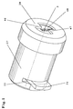
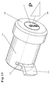
- Fig. 1
- ein Steckzylinderschloß gemäß der Erfindung in perspektivischer Darstellung;
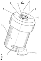
- Fig. 2
- das aus Fig. 1 ersichtliche Steckzylinderschloß, angeordnet in einer Aufnahmeöffnung einer Wand eines zu schützenden Objektes, zum Beispiel eines Warenautomaten, nach einem Einbruchsversuch mit verformtem Schubriegel, ebenfalls in perspektivischer Darstellung;
- Fig. 3
- das aus Fig. 2 ersichtliche Steckzylinderschloß nach dem Einbruchsversuch mit verformtem Schubriegel;
- Fig. 4
- eine teilweise Stirnansicht in Richtung des Pfeiles A der Fig. 5;
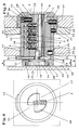
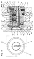
- Fig. 5
- einen Längsschnitt durch ein in einem Warenautomaten oder dergleichen eingebautes Steckzylinderschloß gemäß der Erfindung in verriegeltem Zustand;
- Fig. 6
- eine Teilansicht in Richtung des Pfeiles B der Fig. 7, nach einem Einbruchsversuch und entsprechend verformtem Schubriegel entsprechend Fig. 2 in verriegeltem Zustand;
- Fig. 7
- ein Längsschnitt zu Fig. 6 entsprechend Fig. 5 mit vertormtem Schubriegel;
- Fig. 8
- eine teilweise Stirnansicht in Richtung des Pfeiles C der Fig. 9 nach einem Verdrehen des Zylinderkerns mittels eines nicht dargestellten Flachschlüssels um 90 Grad in Offenstellung;
- Fig. 9
- einen teilweise Längsachsschnitt zu Fig. 8 in Offenstellung;
- Fig. 10
- einen Schubriegel in der Seitenansicht;
- Fig. 11
- eine Ansicht in Richtung des Pfeiles D der Fig. 10;
- Fig. 12
- eine Ansicht auf die hintere Stirnseite eines Steckzylinderschlosses in eingebautem Zustand.
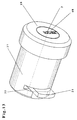
- Fig. 13
- ein Steckzylinderschloß gemäß einer weiteren Ausführungsform der Erfindung in perspektivischer Darstellung;
- Fig. 14
- das aus Fig. 13 ersichtliche Steckzylinderschloß, angeordnet in einer Aufnahmeöffnung einer Wand eines zu schützenden Objektes, zum Beispiel eines Warenautomaten, nach einem Einbruchsversuch mit verformtem Schubriegel, ebenfalls in perspektivischer Darstellung;
- Fig. 15
- das aus Fig. 14 ersichtliche Steckzylinderschloß nach dem Einbruchsversuch mit verformtem Schubriegel;
- Fig. 16
- eine teilweise Stirnansicht in Richtung des Pfeiles A in Fig. 17;
- Fig. 17
- einen Längsschnitt durch ein in einem Warenautomat oder dergleichen eingebauten Steckzylinderschloß gemäß der Erfindung in verriegeltem Zustand;
- Fig. 18
- eine Teilansicht in Richtung des Pfeiles B der Fig. 19, nach einem Einbruchsversuch und entsprechend verformtem Schubriegel entsprechend Fig. 14 in verriegeltem Zustand;
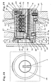
- Fig. 19
- einen Längsschnitt zu Fig. 18 entsprechend Fig. 17 mit verformtem Schubriegel;
- Fig. 20
- eine teilweise Stirnansicht in Richtung des Pfeiles C der Fig. 21 nach einem Verdrehen des Zylinderkerns mittels eines nicht dargestellten Flachschlüssels um 90 Grad in Offenstellung;
- Fig. 21
- einen teilweisen Längsachsschnitt zu Fig. 20 in Offenstellung;
- Fig. 22
- eine perspektivische Darstellung, teils im Schnitt, eines Steckzylinderschlosses;
- Fig. 23
- das aus Fig. 22 ersichtliche Steckzylinderschloß, ebenfalls in perspektivischer Darstellung, teils im Schnitt, wobei der Zylinderkopf nach dem Eindrehen einer Ziehschraube an der Sollbruchstelle abgeschert ist;
- Fig. 24
- das Ansetzen einer Ziehschraube bei einem Zylinderkern mit Sollbruchstelle gemäß der Erfindung, in der Draufsicht und
- Fig. 25
- den aus Fig. 24 ersichtlichen Zylinderkern nach einem weiteren Eindrehen der Ziehschraube gemäß Fig. 24 und dem außermittigen Verlaufen der Ziehschraube.
- Fig. 1
- a cylinder lock according to the invention in perspective;
- Fig. 2
- the plug cylinder lock shown in Figure 1, arranged in a receiving opening of a wall of an object to be protected, for example a vending machine, after an attempted break-in with a deformed slide bolt, also in a perspective view;
- Fig. 3
- the plug-in cylinder lock shown in Figure 2 after the break-in attempt with a deformed slide bolt.
- Fig. 4
- a partial end view in the direction of arrow A of FIG. 5;
- Fig. 5
- a longitudinal section through a plug-in cylinder lock installed in a vending machine or the like according to the invention in the locked state;
- Fig. 6
- a partial view in the direction of arrow B of Figure 7, after a break-in attempt and correspondingly deformed slide bolt according to Figure 2 in the locked state.
- Fig. 7
- a longitudinal section to Figure 6 corresponding to Figure 5 with a standardized slide bolt.
- Fig. 8
- a partial end view in the direction of arrow C of Figure 9 after turning the cylinder core by means of a flat key, not shown, by 90 degrees in the open position;
- Fig. 9
- a partial longitudinal axis section of Figure 8 in the open position.
- Fig. 10
- a slide bar in side view;
- Fig. 11
- a view in the direction of arrow D of Fig. 10;
- Fig. 12
- a view of the rear end of a cylinder lock in the installed state.
- Fig. 13
- a cylinder lock according to a further embodiment of the invention in a perspective view;
- Fig. 14
- the plug-in cylinder lock shown in FIG. 13, arranged in a receiving opening of a wall of an object to be protected, for example a vending machine, after an attempted break-in with a deformed slide bolt, likewise in a perspective view;
- Fig. 15
- the plug-in cylinder lock shown in FIG. 14 after the attempted break-in with a deformed slide bolt;
- Fig. 16
- a partial end view in the direction of arrow A in Fig. 17;
- Fig. 17
- a longitudinal section through a plug-in cylinder lock installed in a vending machine or the like according to the invention in the locked state;
- Fig. 18
- a partial view in the direction of arrow B of Figure 19, after a break-in attempt and correspondingly deformed slide bolt according to Figure 14 in the locked state.
- Fig. 19
- a longitudinal section to Figure 18 corresponding to Figure 17 with a deformed slide bolt.
- Fig. 20
- a partial end view in the direction of arrow C of Figure 21 after turning the cylinder core by means of a flat key, not shown, by 90 degrees in the open position;
- Fig. 21
- a partial longitudinal axis section of Figure 20 in the open position.
- Fig. 22
- a perspective view, partly in section, of a cylinder lock;
- Fig. 23
- the plug-in cylinder lock shown in FIG. 22, also in perspective, partly in section, the cylinder head being sheared off at the predetermined breaking point after a pulling screw has been screwed in;
- Fig. 24
- the application of a pull screw in a cylinder core with predetermined breaking point according to the invention, in plan view and
- Fig. 25
- 24 after a further screwing in of the pull screw according to FIG. 24 and the eccentric running of the pull screw.
Das aus der Zeichnung ersichtliche Steckzylinderschloß weist ein Zylindergehäuse 1 und einen in einer Bohrung drehbeweglich darin angeordneten Zylinderkern 2 auf, der einen in Längsachsrichtung verlaufenden Schlüsselkanal 3 besitzt, in den ein nicht dargestellter Flachschlüssel einsteckbar ist. Der Flachschlüssel kann als Längsrippenprofilflachschlüssel ausgebildet sein und mehrere Vertiefungen aufweisen, durch die er in Längsachsrichtung des Zylinderkernes 2 angeordnete, in parallel zueinander verlaufende Sackbohrungen des Zylinderkerns 2 längsverschieblich angeordnete Kernstifte 4, 5, 6, 7 und 8 steuert, die an ihren den Ausnehmungen des Flachschlüssels zugekehrten Enden konisch zulaufend ausgebildet sind (Fig. 5, 7).The cylinder lock shown in the drawing has a
Koaxial zu den Kernstiften 4, 5, 6, 7 und 8 sind Gehäusestifte 9, 10, 11, 12 und 13 angeordnet, die in parallel zueinander verlaufenden Bohrungen des Zylindergehäuses 1 verschieblich sind. Die Gehäusestifte 9 bis 13 sind jeweils gegen die Rückstellkraft von Druckfedern gelagert, die in der Zeichnung nur schematisch angedeutet sind und die sich jeweils gegen die den zugehörigen Kernstift 4 bis 8 abgekehrten Stirnseite des betreffenden Gehäusestiftes 9 bis 13 unter Vorspannung abstützen, so daß auch die Kernstifte 4 bis 8 entsprechend federbelastet sind. Die Kernstifte 4 bis 8 und die Gehäusestifte 9 bis 13 bilden die Stiftzuhaltungen des Steckzylinderschlosses.Housing pins 9, 10, 11, 12 and 13 are arranged coaxially to the core pins 4, 5, 6, 7 and 8 and are displaceable in bores of the
Das Zylindergehäuse 1 weist einen hinteren (inneren) Endabschnitt 14 auf, der eine nach hinten ausmündende Öffnung 15 besitzt, in der eine Stützscheibe 16 angeordnet ist. Die Stützscheibe 16 ist vorliegend unter Preßpassung in der Öffnung 15 angeordnet und als Stufenscheibe ausgebildet. Die Öffnung 15 ist kreisförmig ausgestaltet. Die Stützscheibe 16 besteht bei der dargestellten Ausführungsform aus einer Zinn-Bronze-Legierung CuSn8 mit zum Beispiel folgender Analyse:
- Cu Rest;
Sn bis bis 0,35;Fe 0,1;Ni 0,3; Pb 0,05;Zn 0,3;sonstige zusammen 0,2; Dichte kg/dm
- Cu balance; Sn 7.5 to 8.5; P 0.01 to 0.35; Fe 0.1; Ni 0.3; Pb 0.05; Zn 0.3; others together 0.2; Density kg / dm 3 8.8.
Die Festigkeitseigenschaften dieser Bronze können folgende betragen:
- Zugfestigkeit in N/mm2 390 bis 700, vorzugsweise 690 N/mm2; 0,2 % Dehngrenze in N/mm2 von 290 bis 700, vorzugsweise 640 N/mm2; Bruchdehnung in Prozent von 60
bis 10, vorzugsweise 10; Brinellhärte 90 bis 250, vorzugsweise 220.
- Tensile strength in N / mm 2 390 to 700, preferably 690 N / mm 2 ; 0.2% proof stress in N / mm 2 from 290 to 700, preferably 640 N / mm 2 ; Elongation at break in percent from 60 to 10, preferably 10; Brinell hardness 90 to 250, preferably 220.
Wie man erkennt, ist die in achsialer Richtung gemessene Dicke F geringer als die achsiale Länge E der Öffnung 15 des Zylindergehäuseabschnittes 14. Auf diese Weise ist ein Achsialspalt 17 zu dem Kopf 18 einer Schraube 19, die in eine Gewindesackbohrung 20 des Zylinderkerns 2 eingeschraubt ist. Die Schraube 19 verbindet getrieblich einen Schubriegel 21 mit dem Zylinderkern 2. Dieser Schubriegel 21 tritt aus einer schlitzförmigen, sich im Umfang über einen Kreissektor erstreckenden Aussparung 22 des Zylindergehäuses 1 heraus. Die Bewegung des Zylinderkerns 2 wird durch einen Anschlagstift 23 begrenzt, der einerseits in einen Radialschlitz 24 eingreift, der sich etwa um 90 Grad oder einen anderen Winkel in Umfangsrichtung des Zylinderkerns 2 erstreckt und der andererseits in einer Durchgangsbohrung 25 des Zylindergehäuses 1 angeordnet ist. Der Kopf des Anschlagstiftes 23 greift in eine Bohrung 26 ein, die in einer Stahlmantelhülse 27 angeordnet ist, die das Zylindergehäuse 1 auf dem größten Teil seiner Länge umschließt. Auf dem nach außen gekehrten Längenabschnitt der Stahlmantelhülse 27 ist von außen eine nach Art einer Muffe oder Hutmutter ausgebildete Schutzhaube 28 aus Stahl aufgesetzt, die mit einem achsialen Längenabschnitt 29 die Stahlmantelhülse 27 auf einem Teil ihres nach außen gekehrten Längenabschnittes und mit einem materialmäßig einstückig damit verbundenen radialen Abschnittes auch die Stirnseite der Stahlmantelhülse 27 und einen Teil der Stirnseite des Zylindergehäuses 1 abdeckt.As can be seen, the thickness F measured in the axial direction is less than the axial length E of the
Die Schutzhaube 28 ist mit der Stahlmantelhülse 27 und mit dem Zylindergehäuse 1 durch mehrere über den Umfang verteilt angeordnete Radialstifte 30 verbunden, die an der äußeren Peripherie des Längenabschnittes 29 enden.The
Bei 31 ist ein Arretierstift angeordnet, der in einen Schlitz 32 einer Wand 33 eingreift. Der Schlitz 32 erstreckt sich in Achslängsrichtung des Steckzylinderschlosses. Über diesen Arretierstift 31 können die Reaktionskräfte, die über den Flachschlüssel auf das Steckzylinderschloß übertragen werden, aufgenommen werden, so daß sich das Steckzylinderschloß nicht verdrehen kann.At 31, a locking pin is arranged which engages in a
Bei 34 ist ein weiterer Radialstift angeordnet, der durch eine Durchgangsbohrung 35 der Stahlmantelhülse 27 hindurchgreift und in eine koaxial dazu angeordnete Sackbohrung 36 eingreift, die in dem Zylindergehäuse 1 angeordnet ist. Dadurch werden das Zylindergehäuse 1 und die Stahlmantelhülse 27 gegeneinander arretiert.At 34, a further radial pin is arranged, which extends through a through
Bei 37 und 38 sowie 39 sind Wände eines zu schützenden Objektes, zum Beispiel eines Spielautomaten, angedeutet. Die Wände 33, 37 und 38 weisen je eine Durchgangsbohrung auf, die koaxial zueinander angeordnet sind und in die das Steckzylinderschloß eingesteckt ist.At 37 and 38 and 39, walls of an object to be protected, for example a slot machine, are indicated. The
Das Maß X liegt bei Spielautomaten in der Regel fest, so daß der Abstand zwischen der Stirnseite 40 und der Innenseite 41 der Wand 39 in der Regel gering ist. Dadurch, daß das Maß X konstruktiv vorgegeben ist, besteht normalerweise wenig Möglichkeit zur konstruktiven Gestaltung.The dimension X is generally fixed in slot machines, so that the distance between the
Wie aus Fig. 12 ersichtlich ist, ist der Zylindergehäuseabschnitt 14 an seiner der Verriegelungsstellung des Schubriegels 21 diametral gegenüberliegenden Seite mit einer tangential angeordneten, in Lächsachsrichtung des Zylindergehäuses 1 verlaufenden Fläche 42 versehen, gegen die sich der Schubriegel 21 bei einem Einbruchsversuch abstützen, auflegen und gegebenenfalls verkeilen kann.As can be seen from FIG. 12, the
Aus den Fig. 10 und 11 ist die Ausbildung des Schubriegels 21 deutlicher zu entnehmen. Hieraus entnimmt man, daß der Schubriegel 21 einen seitwärts ausmündenden Schlitz 43 aufweist in den der Schraubenkopf 18 als Exzenterantrieb eingreift. Der Schubriegel 21 ist durch eine Radialnut geführt. Der Schubriegel 21 ist an seiner Oberseite und Unterseite jeweils nach einem Kreisbogen 44 bzw. 45 verlaufend abgerundet ausgebildet.10 and 11, the design of the
Der Schubriegel 21 besteht bei der dargestellten Ausführungsform aus nicht rostendem Stahl, zum Beispiel aus X 5 CrNi 18 10, Werkstoffnummer 1.4301. Ein solcher Stahl ist ein austenitischer Stahl, der bei Raumtemperatur im abgeschreckten Zustand folgende Eigenschaften aufweist:In the embodiment shown, the
Dichte 7,9 kg/dm3, der Elastizitätsmodul bei 20 Grad Celsius 200 kN/mm2, bei 100 Grad Celsius 194.Density 7.9 kg / dm 3 , the elastic modulus at 20 degrees Celsius 200 kN / mm 2 , at 100 degrees Celsius 194.
Die Stahlmantelhülse 27 besteht ebenfalls aus rostfreiem Stahl X 10 CrNiS 18 9, Werkstoffnummer 1.4305. Hier handelt es sich ebenfalls um einen austenitischen Stahl, der in abgeschrecktem Zustand folgende Werkstoffeigenschaften aufweist:
- Zugfestigkeit 500 bis 700 N/mm2, Bruchdehnung ca. 35 %, Kerbschlagzähigkeit 160 mm nach DIN 17010.
- Tensile strength 500 to 700 N / mm 2 , elongation at break approx. 35%, impact strength 160 mm according to DIN 17010.
Deutlich erkennt man zum Beispiel aus den Fig. 1, 2, 3, 4, 6 und 8, daß die Schutzhaube 28 materialmäßig mit ihr einstückig verbundene, radial gerichtete Sektoren 46 bzw. 47 oder Radialsektoren aufweist, die die nach außen gekehrte Stirnseite 48 des Zylinderkerns 2 auf einem Teil ihrer Fläche übergreifen. Auf diese Weise wird der Zylinderkern 2 weiterhin gegen achsiales Herausziehen gesichert. Diese Radialsektoren 46 und 47 reichen bis unmittelbar an den Schlüsselkanal 3 heran, so daß auch Manipulationen mit Einbruchswerkzeugen erschwert werden.1, 2, 3, 4, 6 and 8 that the
Wird eine Zugkraft P (Fig. 2, 3) auf das Steckzylinderschloß ausgeübt, dann kann dies dazu führen, daß der Schubriegel 21 so wie aus Fig. 2, 3 und 7 ersichtlich nach hinten in Richtung auf die Wand 39 definiert abgebogen wird, weil die tangential verlaufende Fläche 42 eine definierte Verformung des Schubriegels 21 ermöglicht. Wird nun versucht, das Steckzylinderschloß aus den Öffnungen des zu sichernden Objekts herauszuziehen, so führt dies zu einem Verkeilen des nach hinten gebogenen Schubriegels 21 in der betreffenden Ausnehmung der Wand 38, so daß ein Herausziehen unmöglich wird. Je größer nämlich die Zugkraft P auf das Steckzylinderschloß wird, desto größer ist die Verkeilungskraft. Ein Abscheren des Schubriegels 21 ist dadurch nicht möglich. Auch das radiale Deformieren des im Durchmesser vergrößerten Zylindergehäuseabschnitts 14 ist ausgeschlossen, weil dies die Stützscheibe 16 verhindert. Die dabei auftretenden Kräfte verteilen sich radial über den Umfang etwa gleichmäßig in der Öffnung 15.If a tensile force P (Fig. 2, 3) is exerted on the plug-in cylinder lock, then this can lead to the fact that the
Für die aus den Fig. 13 bis 25 ersichtliche Ausführungsform wurden für Teile gleicher Funktion die gleichen Bezugszeichen wie bei der Ausführungsform nach den Fig. 1 bis 12 verwendet. Die Funktionsweise der Ausführungsform nach den Fig. 13 bis 25 entspricht somit grundsätzlich der Ausführungsform nach den Fig. 1 bis 12, so daß hinsichtlich des grundsätzlichen Aufbaus und der Funktionsweise des Steckzylinderschlosses auf die im Zusammenhang mit der Ausführungsform nach den Fig. 1 bis 12 gemachten Ausführungen verwiesen werden kann.For the embodiment shown in FIGS. 13 to 25, the same reference numerals have been used for parts with the same function as in the embodiment according to FIGS. 1 to 12. The operation of the embodiment according to FIGS. 13 to 25 thus corresponds fundamentally to the embodiment according to FIGS. 1 to 12, so that with regard to the basic structure and the operation of the plug-in cylinder lock, those made in connection with the embodiment according to FIGS. 1 to 12 Executions can be referenced.
Die Ausführungsform nach den Fig. 13 bis 25 unterscheidet sich von der vorbeschriebenen Ausführungsform wie folgt:The embodiment according to FIGS. 13 to 25 differs from the previously described embodiment as follows:
Zunächst ist die Schutzhaube 28 nicht mehr - wie bei der Ausführungsform nach den Fig. 1 bis 12 - mit Radialsektoren 46 versehen. Vielmehr ist der Zylinderkern 2 an seinem nach außen gekehrten Endabschnitt mit einem bei der dargestellten Ausführungsform im Durchmesser vergrößerten Zylinderkernkopf 49 versehen, der über eine Sollbruchstelle 50 materialmäßig einstückig mit dem Zylinderkern 2 verbunden ist. Der Zylinderkernkopf 49 kann aber im Bedarfsfalle auch den gleichen Durchmesser wie der Zylinderkern 2 aufweisen.First, the
Die Sollbruchstelle 50 wird durch auf beide Seiten des Schlüsselkanals 3 vorhandene streifenförmige Materialteile gebildet, die bei dem dargestellten Ausführungsbeispiel nach außen durch parallel zueinander verlaufende, symmetrisch zur Drehachse des Zylinderkerns 2 angeordnete Wände 51 und 52 begrenzt wird. Diese Wände 51, 52 werden vorliegend durch je eine Radialnut 53 bzw. 54 gebildet. Die achsiale Breite G kann bei jeder Radialnut 53 bzw. 54 bei einem Ausführungsbeispiel 0,5 mm betragen. Beide Nuten 53 und 54 sind gleich groß und symmetrisch zur Längsachse angeordnet. Die Achsiallänge H des Zylinderkernkopfes 49 beträgt bei diesem Ausführungsbeispiel 6 mm, während die Nuten 53 und 54 etwa im achsialen Abstand von etwa der Nutbreite G hinter dem Zylinderkernkopf 49 angeordnet sind. Selbstverständlich kann die Ausbildung der Sollbruchstelle 50 auch andersThe
ausgeführt werden. Zum Beispiel ist es möglich, mehr als zwei Nuten vorzusehen. Schließlich ist es möglich, statt Nuten 53 und 54, die Sollbruchstelle 50 auch anders herzustellen, zum Beispiel durch mehrere Bohrungen, die parallel oder im Winkel zueinander verlaufen oder durch sonstige Querschnittsverringerungen im Bereich der Sollbruchstelle oder durch die Verwendung unterschiedlicher Materialien für den Zylinderkern 2 und den Zylinderkernkopf 49.be carried out. For example, it is possible to provide more than two grooves. Finally, instead of
Deutlich erkennt man zum Beispiel aus Fig. 23, daß nach einem Abscheren des Zylinderkernkopfes 49 Materialstreifen an der Sollbruchstelle 50 übrig bleiben, die im Querschnitt wesentlich kleiner bemessen sind als der Kreisquerschnitt des Zylinderkerns 2. Dies bedeutet, daß nach dem Überschreiten einer vorbestimmten Zugkraft der Zylinderkernkopf 49 abgeschert wird. Die zum Beispiel durch eine Ziehschraube 55 auf den Zylinderkern 2 aufzuübenden Kräfte können dann so bemessen werden, daß zwar noch der Schubriegel 21 definiert umgebogen werden kann, um sich gegen die Fläche 42 (Fig. 12) anlegen zu können, um die gewünschte Verkeilungswirkung aufzubringen. Bevor jedoch weitere, zerstörerisch große Kräfte auf den Zylinderkern 2 übertragen werden können, wird der Zylinderkernkopf 49 an der Sollbruchstelle 50 abgeschert oder abgerissen, so daß der Aufbruchversuch auch hieran scheitert.It can be clearly seen, for example from FIG. 23, that after the cylinder core head has been sheared off, 49 material strips remain at the
Außerdem erkennt man besonders deutlich aus den Fig. 22 bis 25, daß der Zylinderkernkopf 49 neben der Längsmittenachse (Drehachse) des Zylinderkerns 2 mit einem Vollhartmetallstift 56 versehen ist, der somit orthogonal zur Drehachse des Zylinderkerns 2 verläuft und der an der äußeren Zylindermantelfläche des Zylinderkernkopfes 49 endet.22 to 25 that the
Jenseits der Nuten 53 und 54, also im Steckschloß innen, ist der Zylinderkern 2 bei der dargestellten Ausführungsform auf jeder Seite seiner Drehachse mit je einem weiteren Vollhartmetallstift 57 bzw. 58 versehen. Diese Vollhartmetallstifte 57, 58 können prinzipiell die gleichen Dimensionierungen, zumindest im Durchmesser, erhalten wie der Vollhartmetallstift 56. Auch die Vollhartmetallstifte 57 und 58 enden jeweils an der äußeren Zylindermantelfläche des Zylinderkerns 2, so daß dieser in seiner Drehung nicht behindert wird. Als Hartmetall kommen nicht nur gehärtete Stähle, sondern auch Wolframkarbide und andere, bekannte Hartmetalle in Betracht.Beyond the
Wird nun eine Ziehschraube 55 in den Schlüsselkanal 3 eingeschraubt, so wird sie zunächst durch den Vollhartmetallstift 56 aus ihrer Längsachse abgelenkt (Fig. 25) und stößt dann entweder auf den Vollhartmetallstift 57 oder 58, kann also nur über einen geringen Teil ihrer Länge in den Schlüsselkanal 3 - wenn überhaupt - eingeschraubt werden, so daß sich nicht die beabsichtigten vollen Ziehbeanspruchungen auf den Zylinderkern 2 übertragen lassen. Der Einschraubversuch endet somit in der Regel an dem Vollhartmetallstift 57, so daß nur der Zylinderkernkopf 49 an der Sollbruchstelle 50 abgerissen werden kann. Da man es - wie oben beschrieben - durch die Ausbildung und Anordnung der Sollbruchstelle 50 in der Hand hat, die Abscher- oder Abreißkräfte vorher zu bestimmen, werden auf jeden Fall nur solche Kräfte auf das Steckzylinderschloß und dessen Gehäuse übertragen, die keine schädlichen Beanspruchungen für die Lagerung des Steckzylinderschlosses und dessen Aufnahme bedeuten.If a pulling
Die Schneidspitzen der Ziehschraube 55 werden beim Einschrauben durch den Vollhartmetallstift 56 stumpf, so daß sie sich nicht mehr in den in der Regel aus Messing bestehenden Zylinderkernkopf 49 und den ebenfalls aus Messing bestehenden Zylinderkern 2 einschrauben lassen. Würde eine neue Ziehschraube 55 verwendet, die noch keine stumpfen Schneidspitzen aufweist, so trifft diese auf jeden Fall auf den Vollhartmetallstift 57 und kann dann ebenfalls nicht mehr weiter eingeschraubt werden.The cutting tips of the drawing
Die in der Zusammenfassung, den Patentansprüchen und in der Beschreibung beschriebenen sowie aus der Zeichnung ersichtlichen Merkmale können sowohl einzeln als auch in beliebigen Kombinationen für die Verwirklichung der Erfindung wesentlich sein.The features described in the abstract, the patent claims and in the description and evident from the drawing can be essential for realizing the invention both individually and in any combination.
- 11
- ZylindergehäuseCylinder housing
- 22nd
- ZylinderkernCylinder core
- 33rd
- SchlüsselkanalKey channel
- 44th
- KernstiftCore pin
- 55
-

- 66
-
- 77
-
- 88th
-
- 99
- GehäusestiftHousing pin
- 1010th
-
- 1111
-
- 1212th
-
- 1313
-
- 1414
- Zylindergehäuseabschnitt, innerer, im Durchmesser vergrößerterCylinder housing section, inner, enlarged in diameter
- 1515
- Öffnungopening
- 1616
- StützscheibeSupport disc
- 1717th
-
Achsialspalt zwischen Stützscheibe 16 und Kopf 18Axial gap between
support disk 16 andhead 18 - 1818th
- Kopfhead
- 1919th
- Schraubescrew
- 2020th
- GewindesackbohrungThreaded blind hole
- 2121
- SchubriegelDrawbar
- 2222
- AussparungRecess
- 2323
- AnschlagstiftStop pin
- 2424th
- RadialschlitzRadial slot
- 2525th
- DurchgangsbohrungThrough hole
- 2626
- Bohrungdrilling
- 2727
- StahlmantelhülseSteel jacket sleeve
- 2828
- SchutzhaubeProtective cover
- 2929
- Längenabschnitt, achsialer von 28Longitudinal section, axial of 28
- 3030th
- RadialstiftRadial pin
- 3131
- ArretierstiftLocking pin
- 3232
- Schlitzslot
- 3333
- Wandwall
- 3434
- RadialstiftRadial pin
- 3535
- DurchgangsbohrungThrough hole
- 3636
- SackbohrungBlind hole
- 3737
- Wandwall
- 3838
-
- 3939
-
- 4040
- StirnseiteFace
- 4141
- Innenseiteinside
- 4242
- Flächesurface
- 4343
- Schlitzslot
- 4444
- KreisbogenCircular arc
- 4545
-
- 4646
- Sektor, RadialsektorSector, radial sector
- 4747
- Sektor, RadialsektorSector, radial sector
- 4848
- StirnseiteFace
- 4949
- ZylinderkernkopfCylinder head
- 5050
- SollbruchstellePredetermined breaking point
- 5151
- Wandwall
- 5252
-
- 5353
- RadialnutRadial groove
- 5454
-
- 5555
- ZiehschraubePull screw
- 5656
- VollhartmetallstiftSolid carbide pin
- 5757
-
- 5858
-
- AA
- AnsichtsrichtungView direction
- BB
-
- CC.
-
- DD
-
Länge der Öffnung 15 in 14Length of the
opening 15 in FIG. 14 - EE
-
Dicke der Stützscheibe 16Thickness of the
support disk 16 - FF
- Längelength
- GG
-
Breite der Nuten 53, 54Width of the
grooves - HH
-
Achsiallänge des Zylinderkernkopfes 49Axial length of the
cylinder core head 49 - PP
- Zugkraft beim AufbruchsversuchTraction when trying to break open
- XX
- LängenmaßLinear measure
Claims (37)
Applications Claiming Priority (2)
| Application Number | Priority Date | Filing Date | Title |
|---|---|---|---|
| DE29609077U DE29609077U1 (en) | 1996-05-21 | 1996-05-21 | Plug-in cylinder lock, in particular for use on protective devices and traps for gaming and vending machines, on roller shutter gates, on movable protective grids or the like. |
| DE29609077U | 1996-05-21 |
Publications (3)
| Publication Number | Publication Date |
|---|---|
| EP0808970A2 true EP0808970A2 (en) | 1997-11-26 |
| EP0808970A3 EP0808970A3 (en) | 1998-05-27 |
| EP0808970B1 EP0808970B1 (en) | 1999-08-11 |
Family
ID=8024199
Family Applications (1)
| Application Number | Title | Priority Date | Filing Date |
|---|---|---|---|
| EP96118819A Expired - Lifetime EP0808970B1 (en) | 1996-05-21 | 1996-11-25 | Cylinder lock |
Country Status (3)
| Country | Link |
|---|---|
| EP (1) | EP0808970B1 (en) |
| AT (1) | ATE183277T1 (en) |
| DE (2) | DE29609077U1 (en) |
Cited By (2)
| Publication number | Priority date | Publication date | Assignee | Title |
|---|---|---|---|---|
| EP0957219A1 (en) | 1998-05-09 | 1999-11-17 | August Knapp Schliesstechnik GmbH | Mortise cylinder lock, specially for use with the protection devices of vending or gaming machines |
| US20220389738A1 (en) * | 2021-06-07 | 2022-12-08 | David Truffet | Lock structure and method of protection |
Families Citing this family (2)
| Publication number | Priority date | Publication date | Assignee | Title |
|---|---|---|---|---|
| DE102007062162B4 (en) | 2007-12-21 | 2014-03-20 | Jul.Niederdrenk Gmbh & Co.Kg | immobilizer |
| CN102661084A (en) * | 2012-05-11 | 2012-09-12 | 章景林 | Spring lock head for anti-theft door lock |
Family Cites Families (5)
| Publication number | Priority date | Publication date | Assignee | Title |
|---|---|---|---|---|
| JPS5284100A (en) * | 1976-01-06 | 1977-07-13 | Takigen Mfg Co | Lock device |
| FR2589926B1 (en) * | 1985-11-14 | 1993-12-31 | Neiman Sa | PISTON LOCK WITH SLIDING ROTOR, CLUTCHABLE WITH CONTROL UNIT |
| DE3835816A1 (en) * | 1988-10-21 | 1990-04-26 | Erich Mundhenke | CYLINDER LOCK |
| US5177466A (en) * | 1991-08-05 | 1993-01-05 | Lai Chung C | Lock structure with a warning device |
| AT405669B (en) * | 1995-03-03 | 1999-10-25 | Evva Werke | DRILL LOCK FOR CYLINDER LOCKS |
-
1996
- 1996-05-21 DE DE29609077U patent/DE29609077U1/en not_active Expired - Lifetime
- 1996-11-25 AT AT96118819T patent/ATE183277T1/en not_active IP Right Cessation
- 1996-11-25 EP EP96118819A patent/EP0808970B1/en not_active Expired - Lifetime
- 1996-11-25 DE DE59602711T patent/DE59602711D1/en not_active Expired - Lifetime
Non-Patent Citations (1)
| Title |
|---|
| None |
Cited By (2)
| Publication number | Priority date | Publication date | Assignee | Title |
|---|---|---|---|---|
| EP0957219A1 (en) | 1998-05-09 | 1999-11-17 | August Knapp Schliesstechnik GmbH | Mortise cylinder lock, specially for use with the protection devices of vending or gaming machines |
| US20220389738A1 (en) * | 2021-06-07 | 2022-12-08 | David Truffet | Lock structure and method of protection |
Also Published As
| Publication number | Publication date |
|---|---|
| EP0808970B1 (en) | 1999-08-11 |
| ATE183277T1 (en) | 1999-08-15 |
| EP0808970A3 (en) | 1998-05-27 |
| DE59602711D1 (en) | 1999-09-16 |
| DE29609077U1 (en) | 1996-08-14 |
Similar Documents
| Publication | Publication Date | Title |
|---|---|---|
| DE60219774T2 (en) | VALVE LOCKS | |
| DE69311229T2 (en) | Screwed locking ring for roller chisels and method for producing such a chisel | |
| DE3000227C2 (en) | Hammer for crushing rock or similar materials | |
| EP0957219B1 (en) | Mortise cylinder lock, specially for use with the protection devices of vending or gaming machines | |
| DE4317994C1 (en) | Lock cylinder | |
| EP0808970B1 (en) | Cylinder lock | |
| EP2166179A1 (en) | Lock cylinder, in particular for a door lock | |
| DE29602680U1 (en) | Drilling protection for cylinder locks | |
| EP0896116B1 (en) | Lock cylinder with hardened metal inserts | |
| DE2739644A1 (en) | SCREW LOCKING | |
| DE4037358C2 (en) | Cylinder lock | |
| DE102005001355B4 (en) | Batch work for safekeeping containers | |
| DE29502983U1 (en) | Security lock anti-theft device with emergency or additional bolt | |
| EP0927801B1 (en) | Lock cylinder for a security lock | |
| CH667690A5 (en) | LOCK GUARD FITTING. | |
| AT337034B (en) | CYLINDER LOCK WITH A SECURITY TO PREVENT UNAUTHORIZED OPENING | |
| EP2918760B1 (en) | Espagnolette fitting | |
| EP2499313B1 (en) | Lock cylinder | |
| EP0843765B1 (en) | Double closure cylinder for a security lock | |
| EP0330803A2 (en) | Cylinder for a safety lock | |
| EP0927289B1 (en) | Pin tumbler in a rotating lock cylinder | |
| DE20016652U1 (en) | Parking meter with safety lock designed as a plug-in cylinder lock | |
| DE19719310C1 (en) | Impact beam for comminuting mill | |
| DE10127472A1 (en) | Safety function cylinder core for closing cylinder has two sleeves made from hardened stainless steel to hold core with positive locking and fixedly connected to assembly bolts | |
| DE3430516A1 (en) | Cylinder lock |
Legal Events
| Date | Code | Title | Description |
|---|---|---|---|
| PUAI | Public reference made under article 153(3) epc to a published international application that has entered the european phase |
Free format text: ORIGINAL CODE: 0009012 |
|
| 17P | Request for examination filed |
Effective date: 19961204 |
|
| AK | Designated contracting states |
Kind code of ref document: A2 Designated state(s): AT CH DE LI |
|
| PUAL | Search report despatched |
Free format text: ORIGINAL CODE: 0009013 |
|
| AK | Designated contracting states |
Kind code of ref document: A3 Designated state(s): AT CH DE LI |
|
| 17Q | First examination report despatched |
Effective date: 19980803 |
|
| GRAG | Despatch of communication of intention to grant |
Free format text: ORIGINAL CODE: EPIDOS AGRA |
|
| GRAG | Despatch of communication of intention to grant |
Free format text: ORIGINAL CODE: EPIDOS AGRA |
|
| GRAH | Despatch of communication of intention to grant a patent |
Free format text: ORIGINAL CODE: EPIDOS IGRA |
|
| GRAH | Despatch of communication of intention to grant a patent |
Free format text: ORIGINAL CODE: EPIDOS IGRA |
|
| GRAA | (expected) grant |
Free format text: ORIGINAL CODE: 0009210 |
|
| AK | Designated contracting states |
Kind code of ref document: B1 Designated state(s): AT CH DE LI |
|
| REF | Corresponds to: |
Ref document number: 183277 Country of ref document: AT Date of ref document: 19990815 Kind code of ref document: T |
|
| REG | Reference to a national code |
Ref country code: CH Ref legal event code: NV Representative=s name: ISLER & PEDRAZZINI AG Ref country code: CH Ref legal event code: EP |
|
| REF | Corresponds to: |
Ref document number: 59602711 Country of ref document: DE Date of ref document: 19990916 |
|
| PLBE | No opposition filed within time limit |
Free format text: ORIGINAL CODE: 0009261 |
|
| STAA | Information on the status of an ep patent application or granted ep patent |
Free format text: STATUS: NO OPPOSITION FILED WITHIN TIME LIMIT |
|
| 26N | No opposition filed | ||
| REG | Reference to a national code |
Ref country code: CH Ref legal event code: PUE Owner name: JUL. NIEDERDRENK GMBH & CO. KG Free format text: AUGUST KNAPP SCHLIESSTECHNIK GMBH#BESSEMER STRASSE 5#42551 VELBERT (DE) -TRANSFER TO- JUL. NIEDERDRENK GMBH & CO. KG#ZUM PAPENBRUCH 12#42553 VELBERT (DE) |
|
| REG | Reference to a national code |
Ref country code: CH Ref legal event code: PCAR Free format text: ISLER & PEDRAZZINI AG;POSTFACH 1772;8027 ZUERICH (CH) |
|
| PGFP | Annual fee paid to national office [announced via postgrant information from national office to epo] |
Ref country code: CH Payment date: 20091113 Year of fee payment: 14 Ref country code: AT Payment date: 20091111 Year of fee payment: 14 |
|
| PGFP | Annual fee paid to national office [announced via postgrant information from national office to epo] |
Ref country code: DE Payment date: 20101117 Year of fee payment: 15 |
|
| REG | Reference to a national code |
Ref country code: CH Ref legal event code: PL |
|
| PG25 | Lapsed in a contracting state [announced via postgrant information from national office to epo] |
Ref country code: LI Free format text: LAPSE BECAUSE OF NON-PAYMENT OF DUE FEES Effective date: 20101130 Ref country code: CH Free format text: LAPSE BECAUSE OF NON-PAYMENT OF DUE FEES Effective date: 20101130 |
|
| PG25 | Lapsed in a contracting state [announced via postgrant information from national office to epo] |
Ref country code: AT Free format text: LAPSE BECAUSE OF NON-PAYMENT OF DUE FEES Effective date: 20101125 |
|
| REG | Reference to a national code |
Ref country code: DE Ref legal event code: R119 Ref document number: 59602711 Country of ref document: DE Effective date: 20130601 |
|
| PG25 | Lapsed in a contracting state [announced via postgrant information from national office to epo] |
Ref country code: DE Free format text: LAPSE BECAUSE OF NON-PAYMENT OF DUE FEES Effective date: 20130601 |