EP0808930A1 - Device and method for continuously fulling woven or knitted textile fabrics - Google Patents
Device and method for continuously fulling woven or knitted textile fabrics Download PDFInfo
- Publication number
- EP0808930A1 EP0808930A1 EP97810268A EP97810268A EP0808930A1 EP 0808930 A1 EP0808930 A1 EP 0808930A1 EP 97810268 A EP97810268 A EP 97810268A EP 97810268 A EP97810268 A EP 97810268A EP 0808930 A1 EP0808930 A1 EP 0808930A1
- Authority
- EP
- European Patent Office
- Prior art keywords
- web
- guide channel
- fabric
- fluid
- store
- Prior art date
- Legal status (The legal status is an assumption and is not a legal conclusion. Google has not performed a legal analysis and makes no representation as to the accuracy of the status listed.)
- Withdrawn
Links
- 239000004744 fabric Substances 0.000 title claims abstract description 30
- 239000004753 textile Substances 0.000 title claims description 27
- 238000000034 method Methods 0.000 title claims description 14
- 238000009963 fulling Methods 0.000 title abstract description 3
- 239000000463 material Substances 0.000 claims abstract description 12
- 239000012530 fluid Substances 0.000 claims abstract description 8
- 230000001133 acceleration Effects 0.000 abstract description 8
- 238000010009 beating Methods 0.000 abstract 5
- 230000015654 memory Effects 0.000 description 3
- 238000003801 milling Methods 0.000 description 2
- 230000002730 additional effect Effects 0.000 description 1
- 230000004888 barrier function Effects 0.000 description 1
- 238000007664 blowing Methods 0.000 description 1
- 230000001419 dependent effect Effects 0.000 description 1
- 230000006870 function Effects 0.000 description 1
- 239000007788 liquid Substances 0.000 description 1
- 230000003287 optical effect Effects 0.000 description 1
Images

Classifications
-
- D—TEXTILES; PAPER
- D06—TREATMENT OF TEXTILES OR THE LIKE; LAUNDERING; FLEXIBLE MATERIALS NOT OTHERWISE PROVIDED FOR
- D06C—FINISHING, DRESSING, TENTERING OR STRETCHING TEXTILE FABRICS
- D06C19/00—Breaking or softening of fabrics
-
- D—TEXTILES; PAPER
- D06—TREATMENT OF TEXTILES OR THE LIKE; LAUNDERING; FLEXIBLE MATERIALS NOT OTHERWISE PROVIDED FOR
- D06C—FINISHING, DRESSING, TENTERING OR STRETCHING TEXTILE FABRICS
- D06C17/00—Fulling
Definitions
- the invention relates to a device and a method for continuously milling a web of textile fabrics and knitted fabrics according to the preamble of patent claim 1 or according to the preamble of patent claim 6.
- EP-A-535 287 describes a method and a device for continuously improving the grip and surface, also known as flexing, of textile fabrics and knitted fabrics, in which the web to be treated alternately between a first web store and a second web store by means of pneumatic conveying means - and moved and temporarily saved there in sections. A feed difference is maintained between the conveying directions, the web being fed continuously to the first web store and being continuously removed from the second web store.
- the material web is accelerated in a guide and acceleration channel and in each conveying direction is thrown against an impact surface arranged at the end of the acceleration section and compressed there.
- the textile web can only be guided broadly in the guide channel and is thus thrown against the impact surface.
- the invention is therefore based on the object of improving a method and a device of the aforementioned type in such a way that a wide web of material as a line of goods can be compressed or tumbled on a baffle.
- the material web can still be guided widely in the guiding and acceleration channel, the material web is optimally accelerated; it is nevertheless thrown against the impact surface by the control means as a line of goods.
- Such a fulling treatment can give the textile fabric and knitted fabric a more homogeneous surface and a softer feel.
- the textile web is preferably accelerated in the guide channel with guide members for the fluid used for the acceleration.
- the control means for merging the wide web into a line of goods advantageously have control nozzles which are aligned either at an obtuse angle or approximately transversely to the conveying direction of the web. In the first case, the nozzles can simultaneously cause an additional acceleration of the line of goods that is being formed. In practice, it has proven particularly useful if the control means are designed so that they can be switched on and off, in order to offer the possibility, if necessary, of walking a wide web of goods.
- the material web to be treated is alternately moved back and forth between a first material web memory and a second material web memory and temporarily stored there in sections.
- the web is removed from a web store and fed to the other web store.
- the textile web is accelerated and hurled against an impact surface in each direction of conveyance.
- the web removed from the other web store is subsequently exposed to the same treatment process at least once more.
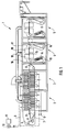
- a machine 1 for milling and shrinking a textile web is shown purely schematically in FIG.
- the machine 1 has two shrink dryers 2 and 3, which are followed by two flexing devices 4 and 5.
- the broad textile web 6, which consists of textile fabrics and / or knitted fabrics, is guided by an endless conveyor belt 7 through the shrink dryer 2 and 3, and dried there to a certain residual moisture.
- the conveyor belt 7 is designed to be permeable to air and is driven via deflection and drive rollers 8 in an endless loop.
- the shrink dryers 2 and 3 are connected to a hot air source 11 via air tubes 9 and a switching element 10. Details of the design and function of these shrink dryers 2 and 3 can be found in European patent application EP-A-535 287 by the same applicant. The content of this patent application is hereby incorporated by reference into the present description.
- the flexing device 4 and 5 has two approximately U-shaped memories 13 and 14, which are connected to one another by a guide and acceleration channel 15.
- baffle surfaces 16 and 17 which are designed like a grid and are provided, against which the textile web 6 is thrown and thus compressed.
- two conveyor groups 18 and 19 consisting of blowing nozzles are provided on the guide channel 15.
- the conveying means groups 18 and 19 are connected to a compressed air source 21 via a flip-flop switching element 20.
- optical scanning means (light barriers) 22 and 23 are provided in the lower region. The textile web 6 can thus be moved back and forth between the two stores 13 and 14 by the conveyor groups 18 and 19 and thus be tumbled, as described in detail in the above patent application.
- control nozzles 26 are provided between the guide channel 15 and the impact surfaces 16 and 17 on both sides and approximately transversely to the conveying direction F, as shown in FIG. 2 with arrows and in Figure 3 in a plan view of the guide channel 15 with the broad textile web 6 can be seen.
- the control nozzles 26 are acted upon by compressed air, as a result of which the wide textile web 6 is brought together to form a strand 25.
- the textile web 6 is brought together over a shorter or longer distance.
- control nozzles 26 can also be acted upon by a pressure fluid such as a liquor or the like, in order to bring about an additional effect at the same time.
- a pressure fluid such as a liquor or the like
- control nozzles 26 ' can also form an obtuse angle ⁇ (shown in dashed lines in FIG. 3) with the respective conveying direction F in order to additionally accelerate the product line 25 formed.
- a plurality of control nozzles 26 '(also shown in dashed lines) can also be provided on the same side of the textile web 6 in order to bring them together in stages to form a web 25.
- the product strand 25 that is formed relaxes in the respective store 13 or 14, so that the textile fabric or knitted fabric again in the opposite direction as a wide web 6 in the guide channel during a further flexing process 15 is drawn in.
- the entrances and exits of the Guide channel 15 formed slit-shaped.
- the slot-shaped entrances and exits can be curved slightly downward at the sides. This additionally prevents the merged web 6 from causing blockages in the slot-shaped entrances and exits of the guide channel 15.
Landscapes
- Engineering & Computer Science (AREA)
- Textile Engineering (AREA)
- Mechanical Engineering (AREA)
- Treatment Of Fiber Materials (AREA)
Abstract
Description
Die Erfindung betrifft eine Vorrichtung und ein Verfahren zum kontinuierlichen Walken einer Warenbahn aus textilen Geweben und Gewirken nach dem Oberbegriff des Patentanspruchs 1, bzw. nach dem Oberbegriff des Patentanspruchs 6.The invention relates to a device and a method for continuously milling a web of textile fabrics and knitted fabrics according to the preamble of patent claim 1 or according to the preamble of
In EP-A-535 287 ist ein Verfahren und eine Vorrichtung zur kontinuierlichen Griff- und Oberflächenverbesserung, auch Walken genannt, von textilen Geweben und Gewirken beschrieben, bei welchem die zu behandelnde Warenbahn mittels pneumatischer Fördermittel wechselweise zwischen einem ersten Warenbahnspeicher und einem zweiten Warenbahnspeicher hin- und herbewegt und dort vorübergehend abschnittweise gespeichert wird. Zwischen den Förderrichtungen wird eine Vorschubdifferenz aufrechterhalten, wobei die Warenbahn dem ersten Warenbahnspeicher kontinuierlich zugeführt und aus dem zweiten Warenbahnspeicher kontinuierlich abgeführt wird. Die Warenbahn wird in einem Führungs- und Beschleunigungskanal beschleunigt und in jeder Förderrichtung gegen eine am Ende der Beschleunigungsstrecke angeordnete Prallfläche geschleudert und dort gestaucht. Die textile Warenbahn kann im Führungskanal ausschliesslich breit geführt werden und wird so gegen die Prallfläche geschleudert.EP-A-535 287 describes a method and a device for continuously improving the grip and surface, also known as flexing, of textile fabrics and knitted fabrics, in which the web to be treated alternately between a first web store and a second web store by means of pneumatic conveying means - and moved and temporarily saved there in sections. A feed difference is maintained between the conveying directions, the web being fed continuously to the first web store and being continuously removed from the second web store. The material web is accelerated in a guide and acceleration channel and in each conveying direction is thrown against an impact surface arranged at the end of the acceleration section and compressed there. The textile web can only be guided broadly in the guide channel and is thus thrown against the impact surface.
Alternativ sind Anordnungen bekannt, bei denen die Ware als Strang gefördert und durch einen mit hoher Geschwindigkeit beschleunigten Flüssigkeits-Strom gegen eine Prallfläche geschleudert wird.Alternatively, arrangements are known in which the goods are conveyed as a strand and are hurled against a baffle by a liquid flow accelerated at high speed.
Der Erfindung liegt demnach die Aufgabe zugrunde, ein Verfahren und eine Vorrichtung der vorgenannten Art derart zu verbessern, dass eine breit geführte Warenbahn als Warenstrang an einer Prallfläche gestaucht oder gewalkt werden kann.The invention is therefore based on the object of improving a method and a device of the aforementioned type in such a way that a wide web of material as a line of goods can be compressed or tumbled on a baffle.
Diese Aufgabe wird vorrichtungsmässig durch eine Vorrichtung mit den Merkmalen des Patentanspruchs 1 und verfahrensmässig durch ein Verfahren mit den Merkmalen des Patentanspruchs 6 gelöst.This object is achieved in terms of the device by a device with the features of claim 1 and in terms of the method by a method with the features of
Da die Warenbahn erfindungsgemäss nach wie vor im Führungs- und Beschleunigungskanal breit geführt werden kann, findet eine optimale Beschleunigung der Warenbahn statt; sie wird dennoch durch die Steuermittel als Warenstrang gegen die Prallfläche geschleudert. Eine solche Walkbehandlung kann dem textilen Gewebe und Gewirke eine homogenere Oberfläche und einen weicheren Griff geben. Die textile Warenbahn wird vorzugsweise mit Führungsorganen für das zur Beschleunigung eingesetzte Fluid im Führungskanal beschleunigt. Die Steuermittel zum Zusammenführen der breit geführten Warenbahn zu einem Warenstrang weisen in vorteilhafter Weise Steuerdüsen auf, die entweder im einem stumpfen Winkel oder etwa quer zur Förderrichtung der Warenbahn ausgerichtet sind. Im ersten Fall können die Düsen gleichzeitig eine zusätzliche Beschleunigung des sich bildenden Warenstranges bewirken. In der Praxis hat sich besonders bewährt, wenn die Steuermittel ein- und ausschaltbar gestaltet sind, um gegebenfalls die Möglichkeit zu bieten, auch eine breit geführte Warenbahn zu walken.Since, according to the invention, the material web can still be guided widely in the guiding and acceleration channel, the material web is optimally accelerated; it is nevertheless thrown against the impact surface by the control means as a line of goods. Such a fulling treatment can give the textile fabric and knitted fabric a more homogeneous surface and a softer feel. The textile web is preferably accelerated in the guide channel with guide members for the fluid used for the acceleration. The control means for merging the wide web into a line of goods advantageously have control nozzles which are aligned either at an obtuse angle or approximately transversely to the conveying direction of the web. In the first case, the nozzles can simultaneously cause an additional acceleration of the line of goods that is being formed. In practice, it has proven particularly useful if the control means are designed so that they can be switched on and off, in order to offer the possibility, if necessary, of walking a wide web of goods.
Es ist beim erfindungsgemässen Verfahren vorteilhaft, wenn die zu behandelnde Warenbahn wechselweise zwischen einem ersten Warenbahnspeicher und einem zweiten Warenbahnspeicher hin- und herbewegt und dort vorübergehend abschnittweise zwischengespeichert wird. Die Warenbahn wird dabei aus einem Warenbahnspeicher abgeführt und dem anderen Warenbahnspeicher zugeführt. Zwischen den beiden Warenbahnspeicher wird die textile Warenbahn beschleunigt und in jeder Förderrichtung gegen eine Prallfläche geschleudert. In der Praxis hat sich bewährt, wenn die aus dem anderen Warenbahnspeicher abgeführte Warenbahn anschliessend mindestens noch einmal dem gleichen Behandlungsverfahren ausgesetzt wird. Es ist jedoch nicht unbedingt notwendig, dass die Warenbahn in beide Förderrichtungen zu einem Warenstrang zusammengeführt wird, sondern dieses könnte auch nur auf einer Seite des Führungskanals vorgesehen werden.In the method according to the invention, it is advantageous if the material web to be treated is alternately moved back and forth between a first material web memory and a second material web memory and temporarily stored there in sections. The web is removed from a web store and fed to the other web store. Between the two web stores, the textile web is accelerated and hurled against an impact surface in each direction of conveyance. In practice it has proven if the web removed from the other web store is subsequently exposed to the same treatment process at least once more. However, it is not absolutely necessary for the web to be brought together in both directions of conveyance to form a line of goods, but this could also be provided only on one side of the guide channel.
Weitere Vorteile der Erfindung folgen aus den abhängigen Patentansprüchen und aus der nachfolgenden Beschreibung, in welcher die Erfindung anhand eines in den schematischen Zeichnungen dargestellten Ausführungsbeispieles näher erläutert wird. Es zeigt:
- Fig. 1
- eine schematische Ansicht einer Maschine zur Behandlung von textilen Geweben und Gewirken,
- Fig. 2
- einen Ausschnitt aus der Figur 1, welcher die Walkvorrichtung genauer darstellt, und
- Fig. 3
- eine Draufsicht auf den Führungskanal mit seitlich angeordneten Düsen.
- Fig. 1
- 1 shows a schematic view of a machine for treating textile fabrics and knitted fabrics,
- Fig. 2
- a section of Figure 1, which shows the flexing device in more detail, and
- Fig. 3
- a plan view of the guide channel with laterally arranged nozzles.
In den Figuren sind für dieselben Elemente jeweils dieselben Bezugszeichen verwendet worden und es betreffen erstmalige Erklärungen alle Figuren, wenn nicht ausdrücklich anders erwähnt.In the figures, the same reference numerals have been used for the same elements, and first-time explanations apply to all figures, unless expressly stated otherwise.
In Figur 1 ist rein schematisch eine Maschine 1 zum Walken und Krumpfen einer textilen Warenbahn gezeigt. Die Maschine 1 weist zwei Krumpftrockner 2 und 3 auf, denen zwei Walkvorrichtungen 4 und 5 nachgeschaltet sind. Die breit geführte textile Warenbahn 6, die aus textilen Geweben und/oder Gewirken besteht, wird von einem endlosen Transportband 7 durch die Krumpftrockner 2 und 3 hindurchgeführt, und dort bis auf einer bestimmten Restfeuchte getrocknet. Das Transportband 7 ist luftdurchlässig ausgebildet und wird über Umlenk- und Antriebsrollen 8 in einer endlos umlaufenden Schlaufe angetrieben. Die Krumpftrockner 2 und 3 sind über Luftröhren 9 und ein Umschaltelement 10 mit einer Heissluftquelle 11 verbunden. Einzelheiten zu der Ausbildung und Funktion dieser Krumpftrockner 2 und 3 können der Europäischen Patentanmeldung EP-A-535 287 derselben Anmelderin entnommen werden. Der Inhalt dieser Patentanmeldung wird durch Bezugnahme hiermit in die vorliegende Beschreibung eingeschlossen.A machine 1 for milling and shrinking a textile web is shown purely schematically in FIG. The machine 1 has two
Die Walkvorrichtung 4 bzw. 5 weist zwei annähernd U-förmige Speicher 13 und 14 auf, die durch einen Führungs- und Beschleunigungskanal 15 miteinander verbunden sind. Stirnseitig zum Führungskanal 15 sind gitterartig ausgebildete und gewölbte Prallflächen 16 und 17 vorgesehen, gegen welche die textile Warenbahn 6 geschleudert und somit gestaucht wird. Zur Beschleunigung der textilen Warenbahn 6 sind zwei aus Blasdüsen bestehenden Fördermittelgruppen 18 und 19 am Führungskanal 15 vorgesehen. Um zwischen den beiden Förderrichtungen der textilen Warenbahn 6 im Führungskanal 15 hin- und herschalten zu können, sind die Fördermittelgruppen 18 und 19 über ein Flip-Flop-Schaltelement 20 mit einer Druckluftquelle 21 verbunden. Um den Füllungsgrad in den beiden Speichern 13 und 14 abzutasten sind optische Abtastmittel (Lichtschranken) 22 und 23 im unteren Bereich vorgesehen.Die textile Warenbahn 6 kann somit zwischen den beiden Speichern 13 und 14 von den Fördermittelgruppen 18 und 19 hin- und herbewegt und somit gewalkt werden, wie ausführlich in der obengenannten Patentanmeldung beschrieben.The
Um die breit geführte textile Warenbahn 3 zu einem Warenstrang 25 zusammenzuführen, sind zwischen dem Führungskanal 15 und den Aufprallflächen 16 und 17 auf beiden Seiten und etwa quer zur Förderrichtung F ausgerichtete, ein- und ausschaltbare Steuerdüsen 26 vorgesehen, wie in Figur 2 mit Pfeilen und in Figur 3 in einer Draufsicht auf den Führungskanal 15 mit der breit geführten textilen Warenbahn 6 ersichtlich ist. Die Steuerdüsen 26 werden mit Druckluft beaufschlagt, wodurch die breit geführte textile Warenbahn 6 zu einem Warenstrang 25 zusammengeführt wird. Abhängig vom Druck der Druckluft und vom Durchmesser der Düsenöffnung der Steuerdüsen 26 wird die textile Warenbahn 6 über eine kürzere oder längere Strecke zusammengeführt. Beim Aufprall des derart gebildeten Warenstranges 25 ergibt sich eine andere Art des Walkens als bei der breit geführten Warenbahn, wie dies aus der vorgenannten Patentanmeldung bekannt ist. Insbesondere ergibt sich dadurch ein weicherer Griff und wird die Oberfläche der solchermassen gewalkten textilen Warenbahn 6 homogener.In order to bring together the
Anstelle mit Druckluft können die Steuerdüsen 26 auch mit einer Druckflüssigkeit wie einer Flotte oder dergleichen beaufschlagt werden, um gleichzeitig einen zusätzlichen Effekt zu bewirken.Instead of compressed air, the
Die Steuerdüsen 26' können auch einen stumpfen Winkel β (gestrichelt in der Figur 3 dargestellt) mit der jeweiligen Förderrichtung F einschliessen, um damit den gebildeten Warenstrang 25 zusätzlich zu beschleunigen. Auch können mehrere Steuerdüsen 26' (ebenfalls gestrichelt dargestellt) auf derselben Seite der textilen Warenbahn 6 vorgesehen sein, um diese stufenweise zu einem Warenstrang 25 zusammenzuführen.The
Da die textile Warenbahn 6 im Führungskanal 15 stets breit geführt bleibt, entspannt sich der gebildete Warenstrang 25 im jeweiligen Speicher 13 oder 14, so dass das textile Gewebe oder Gewirke bei einem weiteren Walkvorgang in die entgegengesetzte Richtung wieder als breit geführte Warenbahn 6 in den Führungskanal 15 hineingezogen wird. Um dafür zu sorgen, dass die textile Warenbahn 6 im Führungskanal 15 stets breit geführt ist, sind mindestens die Ein- und Austritte des Führungskanals 15 schlitzförmig ausgebildet. Um jedoch zu verhindern, dass die Warenbahn 6 schon teilweise im Führungskanal 15 zusammengeführt wird, können die schlitzförmigen Ein- und Austritte seitlich leicht nach unten gekrümmt sein. Dies verhindert zusätzlich, dass die zusammengeführte Warenbahn 6 Verstopfungen in den schlitzförmigen Ein- und Austritte des Führungskanals 15 verursachen kann.Since the
Mit den zusätzlichen Steuerdüsen 26, 26' an den beiden Enden des Führungs- und Beschleunigungskanals 15 können jedoch auch nach wie vor breit geführte textile Warenbahnen 6 in der aus der obengenannten europäischen Patentanmeldung bekannten Art gewalkt werden, indem die Steuerdüsen 26, 26' nicht eingeschaltet werden.With the
Claims (9)
Applications Claiming Priority (2)
| Application Number | Priority Date | Filing Date | Title |
|---|---|---|---|
| CH130296 | 1996-05-23 | ||
| CH1302/96 | 1996-05-23 |
Publications (1)
| Publication Number | Publication Date |
|---|---|
| EP0808930A1 true EP0808930A1 (en) | 1997-11-26 |
Family
ID=4207261
Family Applications (1)
| Application Number | Title | Priority Date | Filing Date |
|---|---|---|---|
| EP97810268A Withdrawn EP0808930A1 (en) | 1996-05-23 | 1997-04-29 | Device and method for continuously fulling woven or knitted textile fabrics |
Country Status (3)
| Country | Link |
|---|---|
| US (1) | US5893933A (en) |
| EP (1) | EP0808930A1 (en) |
| JP (1) | JPH1088466A (en) |
Cited By (5)
| Publication number | Priority date | Publication date | Assignee | Title |
|---|---|---|---|---|
| WO2007054994A1 (en) * | 2005-11-11 | 2007-05-18 | Coramtex S.R.L. | Machine for continuous treatment of a fabric in rope form and relative method |
| EP1425454B1 (en) * | 2001-09-12 | 2007-08-29 | Coramtex S.r.l. | Machine and method for the continuous treatment of a fabric |
| EP2034076A1 (en) | 2007-09-04 | 2009-03-11 | Coramtex S.r.l. | Machine and method for continuous treatment of fabrics in rope form |
| EP2034075A1 (en) | 2007-09-04 | 2009-03-11 | Coramtex S.r.l. | Machine for the treatment of fabric with a drum rotating about an axis non-parallel to the geometric axis of the drum |
| WO2009151409A1 (en) * | 2008-06-10 | 2009-12-17 | Entema Endüstriyel Tesisler Ve Makina Sanayi Limited Sirketi | Softening and swelling machine for woven and knitted fabrics |
Families Citing this family (5)
| Publication number | Priority date | Publication date | Assignee | Title |
|---|---|---|---|---|
| US9657420B2 (en) | 2012-03-30 | 2017-05-23 | Deckers Outdoor Corporation | Sheared wool weaving method |
| WO2014047307A1 (en) * | 2012-09-21 | 2014-03-27 | Eagle Ottawa, Llc | Softening process and system for roll goods |
| EP3114266B1 (en) * | 2014-03-05 | 2018-05-16 | Biancalani S.R.L. | Method and machine for treating textile fabrics with an adjustable air flow |
| US10801139B2 (en) | 2017-01-27 | 2020-10-13 | Deckers Outdoor Corporation | Sheared wool fleece and method for making sheared wool fleece utilizing yarn knitting |
| US11713524B2 (en) | 2017-01-27 | 2023-08-01 | Deckers Outdoor Corporation | Sheared wool fleece and method for making sheared wool fleece utilizing yarn knitting |
Citations (1)
| Publication number | Priority date | Publication date | Assignee | Title |
|---|---|---|---|---|
| EP0535287A1 (en) * | 1991-09-21 | 1993-04-07 | Solipat Ag | Method and apparatus for improving handle and surface of fabrics and knitgoods |
Family Cites Families (8)
| Publication number | Priority date | Publication date | Assignee | Title |
|---|---|---|---|---|
| US4087993A (en) * | 1975-11-03 | 1978-05-09 | Sando Iron Works Co., Ltd. | Heat fulling and water washing apparatus |
| DE3025154A1 (en) * | 1980-07-03 | 1982-01-28 | Brückner-Apparatebau GmbH, 6120 Erbach | METHOD AND DEVICE FOR MAINTAINING A MOVING TEXTILE MATERIAL |
| IT1134730B (en) * | 1980-12-15 | 1986-08-13 | Zonco Federico & Figlio | FULLING MACHINE FOR TEXTILE MATERIALS IN THE FORM OF A ROPE OR BAG |
| JPS6170065A (en) * | 1984-09-13 | 1986-04-10 | 株式会社 日阪製作所 | Liquid treatment apparatus of cloth |
| US4644765A (en) * | 1985-04-29 | 1987-02-24 | Nippon Dyeing Machine Mfg. Co., Ltd. | Continuous treating system for wide cloth |
| IT1187084B (en) * | 1985-08-27 | 1987-12-16 | Biancalani F & C Off Mec | MACHINE FOR WASHING, BREAKING AND FOLLING OF FABRICS, WITH PNEUMATIC DRAGING |
| ATE134397T1 (en) * | 1991-09-21 | 1996-03-15 | Solipat Ag | METHOD AND DEVICE FOR SHRIMPING TEXTILE FABRICS |
| IT1272912B (en) * | 1995-01-19 | 1997-07-01 | Zonco Federico & Figlio | MACHINE FOR THE WET AND DRY TREATMENT OF ROPE OR WIDE FABRICS |
-
1997
- 1997-04-25 US US08/847,492 patent/US5893933A/en not_active Expired - Fee Related
- 1997-04-29 EP EP97810268A patent/EP0808930A1/en not_active Withdrawn
- 1997-05-22 JP JP9131770A patent/JPH1088466A/en active Pending
Patent Citations (1)
| Publication number | Priority date | Publication date | Assignee | Title |
|---|---|---|---|---|
| EP0535287A1 (en) * | 1991-09-21 | 1993-04-07 | Solipat Ag | Method and apparatus for improving handle and surface of fabrics and knitgoods |
Cited By (5)
| Publication number | Priority date | Publication date | Assignee | Title |
|---|---|---|---|---|
| EP1425454B1 (en) * | 2001-09-12 | 2007-08-29 | Coramtex S.r.l. | Machine and method for the continuous treatment of a fabric |
| WO2007054994A1 (en) * | 2005-11-11 | 2007-05-18 | Coramtex S.R.L. | Machine for continuous treatment of a fabric in rope form and relative method |
| EP2034076A1 (en) | 2007-09-04 | 2009-03-11 | Coramtex S.r.l. | Machine and method for continuous treatment of fabrics in rope form |
| EP2034075A1 (en) | 2007-09-04 | 2009-03-11 | Coramtex S.r.l. | Machine for the treatment of fabric with a drum rotating about an axis non-parallel to the geometric axis of the drum |
| WO2009151409A1 (en) * | 2008-06-10 | 2009-12-17 | Entema Endüstriyel Tesisler Ve Makina Sanayi Limited Sirketi | Softening and swelling machine for woven and knitted fabrics |
Also Published As
| Publication number | Publication date |
|---|---|
| JPH1088466A (en) | 1998-04-07 |
| US5893933A (en) | 1999-04-13 |
Similar Documents
| Publication | Publication Date | Title |
|---|---|---|
| EP0818568B1 (en) | Method and apparatus for hydrodynamically entangling the fibres of a web | |
| EP0725178B2 (en) | Method and device for drying and shrinking of textile fabric | |
| EP0535288B1 (en) | Method and apparatus for crimping of fabrics | |
| DE3036669C2 (en) | ||
| EP0535287B1 (en) | Method and apparatus for improving handle and surface of fabrics and knitgoods | |
| EP0808930A1 (en) | Device and method for continuously fulling woven or knitted textile fabrics | |
| DE102005034579A1 (en) | Textile panel e.g. woven fabric, drying and shrinking device e.g. relaxation drier, has nozzles, which blow alternatively in panel transport direction or in opposite direction to panel surfaces, as blowing units for step-back conveyance | |
| EP0358136B1 (en) | Process and apparatus for the treatment of textile webs | |
| EP1530699B1 (en) | Device for preparing textiles | |
| DE1460514B2 (en) | PROCESS AND DEVICE FOR HEAT TREATMENT OF RAILWAY GOODS, IN PARTICULAR TEXTILE GOODS | |
| EP0137066A1 (en) | Apparatus for shrinking and finishing textile webs | |
| EP0669416B1 (en) | Method and device for treating a textile web which is particularly sensitive to stretching | |
| CH673042A5 (en) | ||
| DE2336518B2 (en) | DEVICE FOR TREATMENT OF WEB CHAINS | |
| DE69708046T2 (en) | Finishing machine with pneumatic drive of a strand-like fabric | |
| EP0747309A2 (en) | Method and tentering device for the heat treatment of a textile fabric web | |
| AT408670B (en) | Method and device for the continuous drying and shrinkage of knitted or woven textile fabric | |
| EP1776497B1 (en) | Device for loosening a web of textile material | |
| DE2653227A1 (en) | Sepg. knitted articles joined by thermoplastics yarn - by melting yarn at sepn. zone formed between two endless conveyors moving at different speeds | |
| DE10036058A1 (en) | relaxation dryer | |
| DE2341314A1 (en) | DEVICE FOR FIBER GUIDANCE IN DRAWING PLANTS FOR TEXTILE FIBERS | |
| DE69602567T2 (en) | Crimping device for yarn | |
| DE952166C (en) | Method and device for shrinking running fabric webs | |
| EP0790344A1 (en) | Napping machine | |
| DE7326379U (en) | DEVICE FOR TREATMENT OF WEB CHAINS |
Legal Events
| Date | Code | Title | Description |
|---|---|---|---|
| PUAI | Public reference made under article 153(3) epc to a published international application that has entered the european phase |
Free format text: ORIGINAL CODE: 0009012 |
|
| AK | Designated contracting states |
Kind code of ref document: A1 Designated state(s): AT CH DE ES FR GB IT LI SE |
|
| 17P | Request for examination filed |
Effective date: 19980113 |
|
| GRAG | Despatch of communication of intention to grant |
Free format text: ORIGINAL CODE: EPIDOS AGRA |
|
| 17Q | First examination report despatched |
Effective date: 20000202 |
|
| GRAG | Despatch of communication of intention to grant |
Free format text: ORIGINAL CODE: EPIDOS AGRA |
|
| GRAH | Despatch of communication of intention to grant a patent |
Free format text: ORIGINAL CODE: EPIDOS IGRA |
|
| STAA | Information on the status of an ep patent application or granted ep patent |
Free format text: STATUS: THE APPLICATION IS DEEMED TO BE WITHDRAWN |
|
| 18D | Application deemed to be withdrawn |
Effective date: 20000823 |