EP0808767A2 - Connexion pour une pale de rotor - Google Patents
Connexion pour une pale de rotor Download PDFInfo
- Publication number
- EP0808767A2 EP0808767A2 EP97107427A EP97107427A EP0808767A2 EP 0808767 A2 EP0808767 A2 EP 0808767A2 EP 97107427 A EP97107427 A EP 97107427A EP 97107427 A EP97107427 A EP 97107427A EP 0808767 A2 EP0808767 A2 EP 0808767A2
- Authority
- EP
- European Patent Office
- Prior art keywords
- rotor blade
- support beam
- blade connection
- elastomer
- bending
- Prior art date
- Legal status (The legal status is an assumption and is not a legal conclusion. Google has not performed a legal analysis and makes no representation as to the accuracy of the status listed.)
- Granted
Links
Images
Classifications
-
- B—PERFORMING OPERATIONS; TRANSPORTING
- B64—AIRCRAFT; AVIATION; COSMONAUTICS
- B64C—AEROPLANES; HELICOPTERS
- B64C27/00—Rotorcraft; Rotors peculiar thereto
- B64C27/32—Rotors
- B64C27/33—Rotors having flexing arms
Definitions
- the invention relates to a rotor blade connection, in particular for a helicopter, according to the preamble of patent claim 1.
- Helicopters with an articulated and bearing-free rotor blade connection usually contain a support spar, also called a "flex beam", which is arranged between the lift-generating wing section and the rotor hub and which safely transfers the centrifugal and transverse forces as well as bending and torsional moments from the blade root to the rotor hub and at the same time is flexible about two axes , namely mostly in a hub-side area, and in a wing-side area, must be designed to be rock-elastic and to allow the blade angle adjustment movements around the longitudinal axis to be soft.
- a support spar also called a "flex beam”
- the object of the invention is to provide a rotor blade connection of the type mentioned, in which the damping device is arranged in a manner that is easy to install and with a large volume of elastomer over a limited length of the support beam without impairing the required strength and rigidity behavior of the support beam so that a high degree of structural damping is guaranteed becomes.
- the arrangement of the damping device in the slot-shaped incisions of the support spar which are required anyway for the required elasticity of the drill, results in a space-saving accommodation of a large volume of elastomer in the support spar structure itself, with the special feature that the division into a plurality of in the direction of Slits and individual dampers running on the main beam of the main beam, an extremely homogeneous shear distortion and large-area connection of the individual elastomer layers directly to the bent beam parts and thus a high degree of damping effect with a long service life of the elastomer damper is ensured.
- the intermediate layers of the individual dampers are each fixed to the support bar structure by means of singular fastening points, as a result of which undesired relative displacements between the support bar structure and the intermediate layers and thus disruptive thrust distortions of the elastomer layers, for example under the effect of centrifugal force, are prevented, but at the same time the damping effect of the individual elastomer dampers is retained in full.
- support spar slots and individual dampers can extend continuously over the entire flexurally elastic support spar area, according to claim 3 it is advisable to subdivide the support spar slots in the longitudinal direction of the spar and to arrange an individual damper in each partial slot in order to improve the strength, rigidity and damping behavior of the Tragholms to be able to fine tune each other.
- the surface expansion of the intermediate layers can be controlled electrically, so that the shear distortion of the elastomer layers does not only depend on the size of the bending deformation of the support beam, but also can be influenced by external control interventions. As a result, the damping effect can be significantly improved, especially in the area of small bending vibrations of the support beam.
- these are preferably covered with electrically controlled piezo elements.
- the support beam is preferably provided with a sensor arrangement which absorbs the bending vibrations of the support beam and a control unit which activates the piezo elements in accordance with the sensor signals.
- the elastomeric individual dampers according to claim 7 are expediently arranged in the direction of the swivel bending plane of the swivel-elastic support spar section.
- the support beam and / or the intermediate layers can consist of metal or, as preferred according to claim 8 because of the favorable stiffness and strength behavior, of fiber composite material.
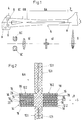
- the blade connection shown in the figures for an articulated and bearingless helicopter rotor contains a support bar 6 made of fiber composite material arranged between the lift-generating wing section 2 and the rotor hub 4, which safely transmits the centrifugal and transverse forces as well as bending and torsional moments from the blade root to the rotor hub 4 and at the same time must form the fictional knuckle and swivel joint and blade angle bearing.
- the support beam 6 consists of a first beam section 6A, which adjoins the wing section 2 (wing profile f according to FIG. 1) and a cruciform, relatively flexible in the pivoting direction S, but comparatively rigid in the impact direction R.
- Cross-section a has, as well as a second spar section 6B, which adjoins the swivel-elastic spar section 6A on the hub side, with a relatively swivel-stiff but resilient cross-sectional profile b in the direction of impact R, which merges towards the hub 4 into a double loop 6C through which the support spar 6 with the aid of connecting bolts 8 is connected to the rotor hub 4.
- slot-shaped incisions 12.1 and 12.2 are provided in the cross-shaped support arms 10.1 and 10.2 of the beam section 6A, of which the incisions 12.2 are provided with an elastomeric damping device for the pivoting bending vibrations in the manner explained below of the stringer 6 are combined.
- the incisions 12.2 consist of a multiplicity of slots of small slot width running parallel to one another in the pivoting direction S and extending from the outer edge of the support arms 10.2 into the interior of the support beam structure.
- each of these slots 12.2 there is an elastomeric individual damper 14, the elastomer layers 16 of which are connected to one another, for example by vulcanization, over a large area, for example by vulcanization, with the adjoining, load-bearing wall sections 18 of the spar arms 10.2, and the intermediate layers 20, which are also made of fiber composite material can exist, are designed so stiff in the direction of their surface extension that they do not participate in the pivot bending deformations of the support bar 6.
- the thickness of the elastomer layers 16 is as small as possible, but may be variable and taking into account the local shear distortions chosen at least so large that the damping effect is fully retained over the required service life.
- FIG. 3 shows the possibility of fixing the intermediate layers 20 to the support bar structure 6 via a singular fastening point 22.
- the slots 12.2 and individual dampers 14 do not extend over the entire length of the swivel-elastic spar section 6A, but are divided in the longitudinal direction of the spar into a plurality of partial slots or damping segments which are each separated from one another by the core structure of the carrying bar 6. In this way, a sensitive coordination of damping behavior and pivoting kinematics of the support bar 6 can be achieved.
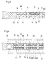
- the passive swivel damping is combined, the slot and damper arrangement largely matching that according to FIGS. 1 to 3.
- Corresponding components are identified by a reference symbol increased by 100 featured.
- the active pivot damping takes place with the aid of electrically controllable, disk-shaped piezo elements 24, with which the intermediate layers 120 are covered, for example in love, so that the areal expansion of the intermediate layers 120 and thus the shear distortion distribution of the elastomer layers 116 can be actively influenced by external electrical control commands.
- sensors 26 are arranged on the support bar structure 106; which record the time-dependent swivel bending deformation behavior of the support beam 106 and report it to a central control unit 28, which converts the sensor signals into appropriate control commands for the individual piezoelectric disks 24 in accordance with a predetermined control program or a data map.
- a central control unit 28 which converts the sensor signals into appropriate control commands for the individual piezoelectric disks 24 in accordance with a predetermined control program or a data map.
- the active thrust distortion in particular in helicopters, is required because of the low internal damping of the rotor when the rotor is just generating little thrust and the passive thrust distortion of the elastomeric individual dampers 114 is low. Otherwise, the construction and mode of operation of the rotor blade connection according to FIG. 4 is the same as in the exemplary embodiments described above.
Landscapes
- Engineering & Computer Science (AREA)
- Mechanical Engineering (AREA)
- Aviation & Aerospace Engineering (AREA)
- Vibration Prevention Devices (AREA)
- Buildings Adapted To Withstand Abnormal External Influences (AREA)
Applications Claiming Priority (2)
| Application Number | Priority Date | Filing Date | Title |
|---|---|---|---|
| DE19620427 | 1996-05-21 | ||
| DE19620427A DE19620427C1 (de) | 1996-05-21 | 1996-05-21 | Rotorblattanschluß |
Publications (3)
| Publication Number | Publication Date |
|---|---|
| EP0808767A2 true EP0808767A2 (fr) | 1997-11-26 |
| EP0808767A3 EP0808767A3 (fr) | 1998-06-03 |
| EP0808767B1 EP0808767B1 (fr) | 2004-10-06 |
Family
ID=7794893
Family Applications (1)
| Application Number | Title | Priority Date | Filing Date |
|---|---|---|---|
| EP97107427A Expired - Lifetime EP0808767B1 (fr) | 1996-05-21 | 1997-05-06 | Connexion pour une pale de rotor |
Country Status (3)
| Country | Link |
|---|---|
| US (1) | US6004099A (fr) |
| EP (1) | EP0808767B1 (fr) |
| DE (2) | DE19620427C1 (fr) |
Cited By (1)
| Publication number | Priority date | Publication date | Assignee | Title |
|---|---|---|---|---|
| FR2774655A1 (fr) * | 1998-02-06 | 1999-08-13 | Eurocopter Deutschland | Rotor a plusieurs pales pour avion a voilure tournante |
Families Citing this family (15)
| Publication number | Priority date | Publication date | Assignee | Title |
|---|---|---|---|---|
| DE19745330C1 (de) * | 1997-10-14 | 1998-11-05 | Eurocopter Deutschland | Rotorblattanschluß |
| KR100534020B1 (ko) * | 2003-07-08 | 2005-12-07 | 한국과학기술연구원 | 자유로운 날갯짓을 구현하는 날개 구동 장치 |
| US8548648B2 (en) * | 2007-07-02 | 2013-10-01 | Sikorsky Aircraft Corporation | Fly-by-wire flight control system with electronic lead/lag damper algorithm |
| EP2246256B1 (fr) * | 2009-04-29 | 2012-10-24 | Eurocopter Deutschland GmbH | Élément de transmission de couple de tension pour pale de rotor anticouple et son procédé de fabrication |
| EP2246259B1 (fr) * | 2009-04-29 | 2012-12-12 | Eurocopter Deutschland GmbH | Aile de rotor avec élément integral de transmission de tension et de couple et son procédé de fabrication |
| CH704541A2 (de) | 2011-02-28 | 2012-08-31 | Marenco Swisshelicopter AG Engineering & Consulting | Rotorblattkopplungsvorrichtung. |
| KR101921574B1 (ko) | 2011-04-07 | 2018-11-26 | 로오드 코포레이션 | 항공기 회전익 모션 제어 및 계장화 모션 제어 유체 장치 |
| DE102011107475B4 (de) * | 2011-07-08 | 2016-10-06 | Deutsches Zentrum für Luft- und Raumfahrt e.V. | Gedämpftes Rotorblatt |
| EP2772430B1 (fr) * | 2013-02-27 | 2016-06-29 | AIRBUS HELICOPTERS DEUTSCHLAND GmbH | Bras de flexion cruciforme d'une partie et procédé de fabrication d'un tel bras |
| EP2899121B1 (fr) | 2014-01-22 | 2016-11-16 | AIRBUS HELICOPTERS DEUTSCHLAND GmbH | Unité de flexion pour rotor à pales multiples sans palier ou sans palier et charnière et aéronef à voilure tournante |
| EP2949579B1 (fr) | 2014-05-28 | 2018-05-23 | AIRBUS HELICOPTERS DEUTSCHLAND GmbH | Unité à bras de flexion avec au moins un élément de flexion torsadé |
| FR3057541B1 (fr) * | 2016-10-14 | 2019-03-29 | Airbus Helicopters | Amortisseur de trainee integre a l'interieur d'une pale d'un rotor |
| CA3004054C (fr) | 2017-05-05 | 2024-02-13 | Laflamme Aero Inc. | Assemblage de moyeu de rotor d'helicoptere et helicoptere comportant ledit assemblage |
| KR102034010B1 (ko) * | 2018-08-20 | 2019-10-18 | 금오공과대학교 산학협력단 | 회전익 자동 강성 조절 장치 |
| CN115263974B (zh) * | 2022-07-20 | 2025-05-09 | 华东交通大学 | 一种基于剪切增稠液体的惯性阻尼器 |
Family Cites Families (19)
| Publication number | Priority date | Publication date | Assignee | Title |
|---|---|---|---|---|
| US3261407A (en) * | 1964-08-05 | 1966-07-19 | Lockheed Aircraft Corp | Helicopter rotor system |
| GB1259802A (en) * | 1969-01-28 | 1972-01-12 | Laser Eng Dev Ltd | Improvements in or relating to means for damping resilient members |
| US4037988A (en) * | 1974-11-25 | 1977-07-26 | The Boeing Company | Flexure having pitch flap coupling |
| DE2558709C3 (de) * | 1975-12-24 | 1982-02-11 | Messerschmitt-Bölkow-Blohm GmbH, 8000 München | Elastomere Dämpfungseinrichtung |
| DE2758086C2 (de) * | 1977-12-24 | 1983-12-01 | Messerschmitt-Bölkow-Blohm GmbH, 8000 München | Rotor für ein Drehflügelflugzeug mit gelenklosem Blattanschluß |
| DE2917301C3 (de) * | 1979-04-28 | 1981-12-17 | Messerschmitt-Bölkow-Blohm GmbH, 8000 München | Schlag-, schwenk- und blattverstellgelenkloser Rotor |
| DE3004451C2 (de) * | 1980-02-07 | 1985-04-04 | Messerschmitt-Bölkow-Blohm GmbH, 8000 München | Elastomere Dämpfungseinrichtung |
| US4519743A (en) * | 1980-03-21 | 1985-05-28 | Massachusetts Institute Of Technology | Helicopter individual blade control system |
| GB2138100B (en) * | 1983-03-18 | 1987-02-11 | Steven Odobasic | Laminated tubular link |
| US4650401A (en) * | 1983-04-07 | 1987-03-17 | Mcdonnell Douglas Helicopter Company | Flat strap cruciform flexure for helicopter rotor systems |
| US4898515A (en) * | 1986-07-23 | 1990-02-06 | United Technologies Corporation | External wrap of composite flexbeam |
| JP2583259B2 (ja) * | 1988-01-08 | 1997-02-19 | 富士重工業株式会社 | ヘリコプタ用フレックスビーム |
| US5224826A (en) * | 1989-07-26 | 1993-07-06 | Massachusetts Institute Of Technology | Piezoelectric helicopter blade flap actuator |
| US5358381A (en) * | 1993-03-19 | 1994-10-25 | Bell Helicopter Textron Inc. | Yoke for helicopter rotor systems |
| US5431538A (en) * | 1993-07-01 | 1995-07-11 | United Technologies Corporation | Hybrid composite flexbeam for a helicopter bearingless main rotor assembly |
| US5378974A (en) * | 1993-07-02 | 1995-01-03 | The United States Of America As Represented By The Secretary Of The Air Force | Vibration damping system |
| FR2708694B1 (fr) * | 1993-07-29 | 1995-10-06 | Hutchinson | Perfectionnement aux supports antivibratoires. |
| JP2758374B2 (ja) * | 1995-02-28 | 1998-05-28 | 株式会社コミュータヘリコプタ先進技術研究所 | ヘリコプタロータの高調波制御装置 |
| US5690474A (en) * | 1996-07-18 | 1997-11-25 | Sikorsky Aircraft Corporation | Optimized composite flexbeam for helicopter tail rotors |
-
1996
- 1996-05-21 DE DE19620427A patent/DE19620427C1/de not_active Expired - Fee Related
-
1997
- 1997-05-06 EP EP97107427A patent/EP0808767B1/fr not_active Expired - Lifetime
- 1997-05-06 DE DE59711982T patent/DE59711982D1/de not_active Expired - Lifetime
- 1997-05-21 US US08/861,199 patent/US6004099A/en not_active Expired - Lifetime
Cited By (1)
| Publication number | Priority date | Publication date | Assignee | Title |
|---|---|---|---|---|
| FR2774655A1 (fr) * | 1998-02-06 | 1999-08-13 | Eurocopter Deutschland | Rotor a plusieurs pales pour avion a voilure tournante |
Also Published As
| Publication number | Publication date |
|---|---|
| EP0808767A3 (fr) | 1998-06-03 |
| DE19620427C1 (de) | 1997-06-12 |
| DE59711982D1 (de) | 2004-11-11 |
| US6004099A (en) | 1999-12-21 |
| EP0808767B1 (fr) | 2004-10-06 |
Similar Documents
| Publication | Publication Date | Title |
|---|---|---|
| EP0808767B1 (fr) | Connexion pour une pale de rotor | |
| DE2701945C2 (de) | Schwingungsdämpfer für einen Hubschrauberrotor | |
| DE2829605C2 (de) | Rotornabe | |
| DE102008025414B4 (de) | Aerodynamisches Profil mit reversibel verformbarer Kontur für Luftfahrzeuge, insbesondere für Drehflügelflugzeuge | |
| DE2541637C3 (de) | Heckrotor fur Drehflügelflugzeuge | |
| EP0019041B1 (fr) | Rotor non-articulé | |
| DE2421764A1 (de) | Rotor fuer drehfluegel-flugzeuge | |
| DE2903524C2 (de) | Schlag- und schwenkgelenkloser Anschluß von Rotorblättern eines Drehflügelflugzeuges | |
| DE69115565T2 (de) | Verbesserte Nabengelenksverbindung für einen Helikopterrotor mit elastischen Blättern | |
| DE19527514C2 (de) | Schnittstelle für die Schwingungsreduktion in strukturdynamischen Systemen | |
| DE2755557A1 (de) | Hubschrauberrotor | |
| EP0022918B1 (fr) | Dispositif de fixation pour éléments de liaison superposés de pales de rotor, en particulier pour helicoptère | |
| EP0019047B1 (fr) | Rotor à pales multiples sans articulation pour hélicoptères | |
| DE60001784T2 (de) | Hubschrauberrotorarm aus Faserverbundstoff | |
| EP0351577B1 (fr) | Rotor, en particulier pour un avion à voilure tournante | |
| DE3879744T2 (de) | Biegeplatte für den Rotor eines Hubschraubers. | |
| DE2638148B2 (de) | Rotor für ein Drehflügelflugzeug | |
| EP1144248B1 (fr) | Profil ajustable de pale de rotor de giravion | |
| DE2932441C2 (de) | Dämpfungseinrichtung für ein Rotorblatt | |
| DE10334267A1 (de) | Rotorblatt mit elastisch beweglicher Rotorblatt-Klappe sowie Drehflügelflugzeug mit einem solchen Rotorblatt | |
| EP2228299B1 (fr) | Actionnement anisotrope d'une pointe de pale de rotor d'hélicoptère | |
| DE19748682B4 (de) | Stützlager-Federelement und Stützlager für Hubschrauberheckrotoren und Tragstrukturen zum Einsatz im Weltraum | |
| DE19837802C1 (de) | Rotorblatt für einen lagerlosen Rotor eines Hubschraubers | |
| DE3707333A1 (de) | Rotor, insbesondere eines drehfluegelflugzeugs | |
| DE10001700B4 (de) | Aerodynamisches Bauteil mit veränderlicher Geometrie |
Legal Events
| Date | Code | Title | Description |
|---|---|---|---|
| PUAI | Public reference made under article 153(3) epc to a published international application that has entered the european phase |
Free format text: ORIGINAL CODE: 0009012 |
|
| AK | Designated contracting states |
Kind code of ref document: A2 Designated state(s): DE FR GB IT |
|
| 17P | Request for examination filed |
Effective date: 19971219 |
|
| PUAL | Search report despatched |
Free format text: ORIGINAL CODE: 0009013 |
|
| RHK1 | Main classification (correction) |
Ipc: B64C 27/35 |
|
| AK | Designated contracting states |
Kind code of ref document: A3 Designated state(s): DE FR GB IT |
|
| GRAP | Despatch of communication of intention to grant a patent |
Free format text: ORIGINAL CODE: EPIDOSNIGR1 |
|
| RAP1 | Party data changed (applicant data changed or rights of an application transferred) |
Owner name: EUROCOPTER DEUTSCHLAND GMBH |
|
| GRAS | Grant fee paid |
Free format text: ORIGINAL CODE: EPIDOSNIGR3 |
|
| GRAA | (expected) grant |
Free format text: ORIGINAL CODE: 0009210 |
|
| AK | Designated contracting states |
Kind code of ref document: B1 Designated state(s): DE FR GB IT |
|
| REG | Reference to a national code |
Ref country code: GB Ref legal event code: FG4D Free format text: NOT ENGLISH |
|
| REF | Corresponds to: |
Ref document number: 59711982 Country of ref document: DE Date of ref document: 20041111 Kind code of ref document: P |
|
| GBT | Gb: translation of ep patent filed (gb section 77(6)(a)/1977) |
Effective date: 20050118 |
|
| ET | Fr: translation filed | ||
| PLBE | No opposition filed within time limit |
Free format text: ORIGINAL CODE: 0009261 |
|
| STAA | Information on the status of an ep patent application or granted ep patent |
Free format text: STATUS: NO OPPOSITION FILED WITHIN TIME LIMIT |
|
| 26N | No opposition filed |
Effective date: 20050707 |
|
| PGFP | Annual fee paid to national office [announced via postgrant information from national office to epo] |
Ref country code: GB Payment date: 20070522 Year of fee payment: 11 |
|
| PGFP | Annual fee paid to national office [announced via postgrant information from national office to epo] |
Ref country code: IT Payment date: 20070525 Year of fee payment: 11 |
|
| PGFP | Annual fee paid to national office [announced via postgrant information from national office to epo] |
Ref country code: FR Payment date: 20070516 Year of fee payment: 11 |
|
| GBPC | Gb: european patent ceased through non-payment of renewal fee |
Effective date: 20080506 |
|
| REG | Reference to a national code |
Ref country code: FR Ref legal event code: ST Effective date: 20090119 |
|
| PG25 | Lapsed in a contracting state [announced via postgrant information from national office to epo] |
Ref country code: FR Free format text: LAPSE BECAUSE OF NON-PAYMENT OF DUE FEES Effective date: 20080602 |
|
| PG25 | Lapsed in a contracting state [announced via postgrant information from national office to epo] |
Ref country code: GB Free format text: LAPSE BECAUSE OF NON-PAYMENT OF DUE FEES Effective date: 20080506 |
|
| PG25 | Lapsed in a contracting state [announced via postgrant information from national office to epo] |
Ref country code: IT Free format text: LAPSE BECAUSE OF NON-PAYMENT OF DUE FEES Effective date: 20080506 |
|
| PGFP | Annual fee paid to national office [announced via postgrant information from national office to epo] |
Ref country code: DE Payment date: 20110505 Year of fee payment: 15 |
|
| REG | Reference to a national code |
Ref country code: DE Ref legal event code: R119 Ref document number: 59711982 Country of ref document: DE Effective date: 20121201 |
|
| PG25 | Lapsed in a contracting state [announced via postgrant information from national office to epo] |
Ref country code: DE Free format text: LAPSE BECAUSE OF NON-PAYMENT OF DUE FEES Effective date: 20121201 |