EP0808767A2 - Rotor blade connection - Google Patents
Rotor blade connection Download PDFInfo
- Publication number
- EP0808767A2 EP0808767A2 EP97107427A EP97107427A EP0808767A2 EP 0808767 A2 EP0808767 A2 EP 0808767A2 EP 97107427 A EP97107427 A EP 97107427A EP 97107427 A EP97107427 A EP 97107427A EP 0808767 A2 EP0808767 A2 EP 0808767A2
- Authority
- EP
- European Patent Office
- Prior art keywords
- rotor blade
- support beam
- blade connection
- elastomer
- bending
- Prior art date
- Legal status (The legal status is an assumption and is not a legal conclusion. Google has not performed a legal analysis and makes no representation as to the accuracy of the status listed.)
- Granted
Links
Images
Classifications
-
- B—PERFORMING OPERATIONS; TRANSPORTING
- B64—AIRCRAFT; AVIATION; COSMONAUTICS
- B64C—AEROPLANES; HELICOPTERS
- B64C27/00—Rotorcraft; Rotors peculiar thereto
- B64C27/32—Rotors
- B64C27/33—Rotors having flexing arms
Definitions
- the invention relates to a rotor blade connection, in particular for a helicopter, according to the preamble of patent claim 1.
- Helicopters with an articulated and bearing-free rotor blade connection usually contain a support spar, also called a "flex beam", which is arranged between the lift-generating wing section and the rotor hub and which safely transfers the centrifugal and transverse forces as well as bending and torsional moments from the blade root to the rotor hub and at the same time is flexible about two axes , namely mostly in a hub-side area, and in a wing-side area, must be designed to be rock-elastic and to allow the blade angle adjustment movements around the longitudinal axis to be soft.
- a support spar also called a "flex beam”
- the object of the invention is to provide a rotor blade connection of the type mentioned, in which the damping device is arranged in a manner that is easy to install and with a large volume of elastomer over a limited length of the support beam without impairing the required strength and rigidity behavior of the support beam so that a high degree of structural damping is guaranteed becomes.
- the arrangement of the damping device in the slot-shaped incisions of the support spar which are required anyway for the required elasticity of the drill, results in a space-saving accommodation of a large volume of elastomer in the support spar structure itself, with the special feature that the division into a plurality of in the direction of Slits and individual dampers running on the main beam of the main beam, an extremely homogeneous shear distortion and large-area connection of the individual elastomer layers directly to the bent beam parts and thus a high degree of damping effect with a long service life of the elastomer damper is ensured.
- the intermediate layers of the individual dampers are each fixed to the support bar structure by means of singular fastening points, as a result of which undesired relative displacements between the support bar structure and the intermediate layers and thus disruptive thrust distortions of the elastomer layers, for example under the effect of centrifugal force, are prevented, but at the same time the damping effect of the individual elastomer dampers is retained in full.
- support spar slots and individual dampers can extend continuously over the entire flexurally elastic support spar area, according to claim 3 it is advisable to subdivide the support spar slots in the longitudinal direction of the spar and to arrange an individual damper in each partial slot in order to improve the strength, rigidity and damping behavior of the Tragholms to be able to fine tune each other.
- the surface expansion of the intermediate layers can be controlled electrically, so that the shear distortion of the elastomer layers does not only depend on the size of the bending deformation of the support beam, but also can be influenced by external control interventions. As a result, the damping effect can be significantly improved, especially in the area of small bending vibrations of the support beam.
- these are preferably covered with electrically controlled piezo elements.
- the support beam is preferably provided with a sensor arrangement which absorbs the bending vibrations of the support beam and a control unit which activates the piezo elements in accordance with the sensor signals.
- the elastomeric individual dampers according to claim 7 are expediently arranged in the direction of the swivel bending plane of the swivel-elastic support spar section.
- the support beam and / or the intermediate layers can consist of metal or, as preferred according to claim 8 because of the favorable stiffness and strength behavior, of fiber composite material.
- the blade connection shown in the figures for an articulated and bearingless helicopter rotor contains a support bar 6 made of fiber composite material arranged between the lift-generating wing section 2 and the rotor hub 4, which safely transmits the centrifugal and transverse forces as well as bending and torsional moments from the blade root to the rotor hub 4 and at the same time must form the fictional knuckle and swivel joint and blade angle bearing.
- the support beam 6 consists of a first beam section 6A, which adjoins the wing section 2 (wing profile f according to FIG. 1) and a cruciform, relatively flexible in the pivoting direction S, but comparatively rigid in the impact direction R.
- Cross-section a has, as well as a second spar section 6B, which adjoins the swivel-elastic spar section 6A on the hub side, with a relatively swivel-stiff but resilient cross-sectional profile b in the direction of impact R, which merges towards the hub 4 into a double loop 6C through which the support spar 6 with the aid of connecting bolts 8 is connected to the rotor hub 4.
- slot-shaped incisions 12.1 and 12.2 are provided in the cross-shaped support arms 10.1 and 10.2 of the beam section 6A, of which the incisions 12.2 are provided with an elastomeric damping device for the pivoting bending vibrations in the manner explained below of the stringer 6 are combined.
- the incisions 12.2 consist of a multiplicity of slots of small slot width running parallel to one another in the pivoting direction S and extending from the outer edge of the support arms 10.2 into the interior of the support beam structure.
- each of these slots 12.2 there is an elastomeric individual damper 14, the elastomer layers 16 of which are connected to one another, for example by vulcanization, over a large area, for example by vulcanization, with the adjoining, load-bearing wall sections 18 of the spar arms 10.2, and the intermediate layers 20, which are also made of fiber composite material can exist, are designed so stiff in the direction of their surface extension that they do not participate in the pivot bending deformations of the support bar 6.
- the thickness of the elastomer layers 16 is as small as possible, but may be variable and taking into account the local shear distortions chosen at least so large that the damping effect is fully retained over the required service life.
- FIG. 3 shows the possibility of fixing the intermediate layers 20 to the support bar structure 6 via a singular fastening point 22.
- the slots 12.2 and individual dampers 14 do not extend over the entire length of the swivel-elastic spar section 6A, but are divided in the longitudinal direction of the spar into a plurality of partial slots or damping segments which are each separated from one another by the core structure of the carrying bar 6. In this way, a sensitive coordination of damping behavior and pivoting kinematics of the support bar 6 can be achieved.
- the passive swivel damping is combined, the slot and damper arrangement largely matching that according to FIGS. 1 to 3.
- Corresponding components are identified by a reference symbol increased by 100 featured.
- the active pivot damping takes place with the aid of electrically controllable, disk-shaped piezo elements 24, with which the intermediate layers 120 are covered, for example in love, so that the areal expansion of the intermediate layers 120 and thus the shear distortion distribution of the elastomer layers 116 can be actively influenced by external electrical control commands.
- sensors 26 are arranged on the support bar structure 106; which record the time-dependent swivel bending deformation behavior of the support beam 106 and report it to a central control unit 28, which converts the sensor signals into appropriate control commands for the individual piezoelectric disks 24 in accordance with a predetermined control program or a data map.
- a central control unit 28 which converts the sensor signals into appropriate control commands for the individual piezoelectric disks 24 in accordance with a predetermined control program or a data map.
- the active thrust distortion in particular in helicopters, is required because of the low internal damping of the rotor when the rotor is just generating little thrust and the passive thrust distortion of the elastomeric individual dampers 114 is low. Otherwise, the construction and mode of operation of the rotor blade connection according to FIG. 4 is the same as in the exemplary embodiments described above.
Landscapes
- Engineering & Computer Science (AREA)
- Mechanical Engineering (AREA)
- Aviation & Aerospace Engineering (AREA)
- Vibration Prevention Devices (AREA)
- Buildings Adapted To Withstand Abnormal External Influences (AREA)
Abstract
Bei einem Rotorblattanschluß, insbesondere für einen Hubschrauber, mit einem den auftriebserzeugenden Flügelabschnitt des Rotorblatts flieh- und querkraft- sowie biege- und torsionsmomentübertragend mit der Rotornabe verbindenden drill- und zumindest in einer Hauptebene biegeelastischen Tragholm (6A) und einer diesem zugeordneten, wechselweise aus Elastomer- und in Richtung der Flächenerstreckung steifen Zwischenschichten (16, 20) aufgebauten Dämpfungseinrichtung für die Biegeschwingungen des Tragholms wird erfindungsgemäß eine platzsparende Unterbringung eines großen Elastomervolumens und eine hochgradige Dämpfungswirkung dadurch erreicht, daß die Dämpfungseinrichtung aus einer Vielzahl separater, mit ihren Elastomer- und Zwischenschichten in Richtung der Hauptbiegeebene (S) des Tragholms angeordneter Einzeldämpfer (14) besteht, die jeweils in die Tragholmstruktur in vom Außenrand ins Tragholminnere im wesentlichen parallel zueinander verlaufenden Schlitzen (12.2) unter flächiger Bindung der beiden äußeren Elastomerschichten jedes Einzeldämpfers an die angrenzenden Tragholmabschnitte (18) integriert sind.
Description
Die Erfindung bezieht sich auf einen Rotorblattanschluß, insbesondere für einen Hubschrauber, nach dem Oberbegriff des Patentanspruchs 1.The invention relates to a rotor blade connection, in particular for a helicopter, according to the preamble of patent claim 1.
Hubschrauber mit einem gelenk- und lagerlosen Rotorblattanschluß enthalten üblicherweise einen zwischen auftriebserzeugendem Flügelabschnitt und Rotornabe angeordneten Tragholm, auch "Flexbeam" genannt, der die Flieh- und Querkräfte sowie Biege- und Torsionsmomente sicher von der Blattwurzel an die Rotornabe übertragen und zugleich um zwei Achsen biegeelastisch, nämlich zumeist in einem nabenseitigen Bereich schlag- und in einem flügelseitigen Bereich schwenkelastisch sowie zur Ermöglichung der Blattwinkelverstellbewegungen um die Längsachse drillweich ausgebildet sein muß. Die Schwingungsdämpfung eines derartigen Tragholms erfolgt mit Hilfe eines Elastomerdämpfers, der entweder als gesonderte Baueinheit zwischen Rotornabe und Tragholm angeordnet oder, wie aus der DE 25 58 709 oder der DE 27 58 086 bekannt, nach Art eines oberflächenseitigen Belages unmittelbar auf den Tragholm aufgebracht ist. Dabei besteht jedoch die Schwierigkeit, einen Dämpfer mit einem ausreichend großen Elastomervolumen so an die Tragholmstruktur anzubinden, daß die einzelnen Elastomerschichten unter der Wirkung der Rotorblatt-Schwenkbewegungen möglichst homogen schubverzerrt werden, wie dies erforderlich ist, um eine wirksame Dämpfung der teilweise sehr kleinen Schwenkbiegeverformungen des Tragholms zu erhalten.Helicopters with an articulated and bearing-free rotor blade connection usually contain a support spar, also called a "flex beam", which is arranged between the lift-generating wing section and the rotor hub and which safely transfers the centrifugal and transverse forces as well as bending and torsional moments from the blade root to the rotor hub and at the same time is flexible about two axes , namely mostly in a hub-side area, and in a wing-side area, must be designed to be rock-elastic and to allow the blade angle adjustment movements around the longitudinal axis to be soft. The vibration damping of such a beam takes place with the aid of an elastomer damper, which is either arranged as a separate structural unit between the rotor hub and the support beam or, as is known from DE 25 58 709 or DE 27 58 086, is applied directly to the support beam in the manner of a surface coating. However, there is the difficulty of connecting a damper with a sufficiently large elastomer volume to the support beam structure in such a way that the individual elastomer layers are thrust-distorted as homogeneously as possible under the effect of the rotor blade pivoting movements, as is necessary in order to effectively damp the sometimes very small pivoting bending deformations of the Get Tragholms.
Aufgabe der Erfindung ist es, einen Rotorblattanschluß der eingangs genannten Art zu schaffen, bei dem die Dämpfungseinrichtung auf einbaugünstige Weise und mit einem großen Elastomervolumen auf einer begrenzten Tragholmlänge ohne Beeinträchtigung des geforderten Festigkeits- und Steifigkeitsverhaltens des Tragholms so angeordnet ist, daß eine hochgradige Strukturdämpfung garantiert wird.The object of the invention is to provide a rotor blade connection of the type mentioned, in which the damping device is arranged in a manner that is easy to install and with a large volume of elastomer over a limited length of the support beam without impairing the required strength and rigidity behavior of the support beam so that a high degree of structural damping is guaranteed becomes.
Diese Aufgabe wird erfindungsgemäß durch den im Patentanspruch 1 gekennzeichneten Rotorblattanschluß gelöst.This object is achieved by the rotor blade connection characterized in claim 1.
Erfindungsgemäß wird durch die Anordnung der Dämpfungseinrichtung in den für die erforderliche Drillelastizität ohnehin benötigten, schlitzförmigen Einschnitten des Tragholms eine platzsparende Unterbringung eines großen Elastomervolumens in der Tragholmstruktur selbst erreicht, mit der Besonderheit, daß durch die Aufteilung in eine Vielzahl von in Richtung der Tragholm-Hauptbiegeebene verlaufenden Schlitzen und Einzeldämpfern eine äußerst homogene Schubverzerrung und großflächige Anbindung der einzelnen Elastomerschichten unmittelbar an die biegeverformten Tragholmabschnitte und dadurch eine hochgradige Dämpfungswirkung bei zugleich langer Lebensdauer des Elastomerdämpfers sichergestellt wird.According to the invention, the arrangement of the damping device in the slot-shaped incisions of the support spar, which are required anyway for the required elasticity of the drill, results in a space-saving accommodation of a large volume of elastomer in the support spar structure itself, with the special feature that the division into a plurality of in the direction of Slits and individual dampers running on the main beam of the main beam, an extremely homogeneous shear distortion and large-area connection of the individual elastomer layers directly to the bent beam parts and thus a high degree of damping effect with a long service life of the elastomer damper is ensured.
In weiterer vorteilhafter Ausgestaltung der Erfindung sind die Zwischenschichten der Einzeldämpfer gemäß Anspruch 2 jeweils über singuläre Befestigungsstellen an der Tragholmstruktur fixiert, wodurch ungewollte Relativverschiebungen zwischen der Tragholmstruktur und den Zwischenschichten und somit störende Schubverzerrungen der Elastomerschichten, etwa unter Fliehkraftwirkung, verhindert werden, gleichzeitig aber die Dämpfungswirkung der einzelnen Elastomerdämpfer in vollem Umfang erhalten bleibt.In a further advantageous embodiment of the invention, the intermediate layers of the individual dampers are each fixed to the support bar structure by means of singular fastening points, as a result of which undesired relative displacements between the support bar structure and the intermediate layers and thus disruptive thrust distortions of the elastomer layers, for example under the effect of centrifugal force, are prevented, but at the same time the damping effect of the individual elastomer dampers is retained in full.
Zwar können sich die Tragholmschlitze und Einzeldämpfer durchgehend über den gesamten biegeelastischen Tragholmbereich erstrecken, nach Anspruch 3 empfiehlt es sich jedoch, die Tragholmschlitze in Holm-Längsrichtung zu unterteilen und in jedem Teilschlitz einen Einzeldämpfer anzuordnen, um so das Festigkeits-, Steifigkeits- und Dämpfungsverhalten des Tragholms feinfühlig aufeinander abstimmen zu können.Although the support spar slots and individual dampers can extend continuously over the entire flexurally elastic support spar area, according to claim 3 it is advisable to subdivide the support spar slots in the longitudinal direction of the spar and to arrange an individual damper in each partial slot in order to improve the strength, rigidity and damping behavior of the Tragholms to be able to fine tune each other.
In weiterer, besonders bevorzugter Ausgestaltung der Erfindung ist gemäß Anspruch 4 die Flächendehnung der Zwischenschichten elektrisch steuerbar, so daß die Schubverzerrung der Elastomerschichten nicht allein von der Größe der Biegeverformung des Tragholms abhängig, sondern zusätzlich durch äußere Steuereingriffe beeinflußbar ist. Hierdurch läßt sich die Dämpfungswirkung vor allem im Bereich kleiner Biegeschwingungen des Tragholms wesentlich verbessern. Im Hinblick auf eine baulich einfache Steuerung der Flächendehnung der Zwischenschichten sind diese gemäß Anspruch 5 vorzugsweise mit elektrisch angesteuerten Piezoelementen belegt. In Verbindung mit Elastomerdämpfern können solche Piezobeläge wegen ihrer hohen Biegeempfindlichkeit im allgemeinen zwar nur in beschränktem Umfang verwendet werden, im Rahmen der Erfindung sind sie jedoch aufgrund ihrer speziellen Flächenausrichtung - ebenso wie die Zwischenschichten - nur sehr geringen Biegeverformungen ausgesetzt und daher problemlos zur Steuerung der Dämpfungswirkung einsetzbar. Aus Gründen einer selbsttätigen Steuerung mit einer erwünschten Steuercharakteristik ist der Tragholm gemäß Anspruch 6 vorzugsweise mit einer die Biegeschwingungen des Tragholms aufnehmenden Sensoranordnung und einer die Piezoelemente nach Maßgabe der Sensorsignale aktivierenden Steuereinheit versehen.In a further, particularly preferred embodiment of the invention, the surface expansion of the intermediate layers can be controlled electrically, so that the shear distortion of the elastomer layers does not only depend on the size of the bending deformation of the support beam, but also can be influenced by external control interventions. As a result, the damping effect can be significantly improved, especially in the area of small bending vibrations of the support beam. With regard to a structurally simple control of the surface expansion of the intermediate layers, these are preferably covered with electrically controlled piezo elements. In connection with elastomer dampers, such piezo coverings can generally only be used to a limited extent because of their high sensitivity to bending, but within the scope of the invention, due to their special surface orientation - like the intermediate layers - they are only exposed to very slight bending deformations and therefore can be used to control the damping effect without problems applicable. For reasons of automatic control with a desired control characteristic, the support beam is preferably provided with a sensor arrangement which absorbs the bending vibrations of the support beam and a control unit which activates the piezo elements in accordance with the sensor signals.
Wie bereits erwähnt, müssen bei einem Hubschrauber-Rotorblattanschluß vor allem die Schwenkbiegeschwingungen des Tragholms gedämpft werden, und dementsprechend sind die elastomeren Einzeldämpfer nach Anspruch 7 zweckmäßigerweise in Richtung der Schwenkbiegeebene des schwenkelastischen Tragholmabschnitts angeordnet.As already mentioned, in a helicopter rotor blade connection, above all, the swivel bending vibrations of the support spar must be damped, and accordingly the elastomeric individual dampers according to claim 7 are expediently arranged in the direction of the swivel bending plane of the swivel-elastic support spar section.
Der Tragholm und/oder die Zwischenschichten können aus Metall oder, wie nach Anspruch 8 wegen des günstigen Steifigkeits- und Festigkeitsverhaltens bevorzugt, aus Faserverbundwerkstoff bestehen.The support beam and / or the intermediate layers can consist of metal or, as preferred according to
Die Erfindung wird nunmehr anhand von Ausführungsbeispielen in Verbindung mit den Zeichnungen näher erläutert. Es zeigen in stark schematisierter Darstellung:
- Fig. 1
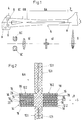
- einen Blattanschluß für ein Hubschrauber-Rotorblatt in der Aufsicht zusammen mit den verschiedenen Querschnitten;
- Fig. 2
- eine vergrößerte Darstellung des schwenkelastischen Tragholmabschnitts im Querschnitt;
- Fig. 3
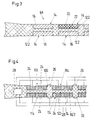
- die Anordnung von in Holm-Längsrichtung verteilten Einzeldämpfern; und
- Fig. 4
- eine der Fig. 3 entsprechende Darstellung eines Rotorblattanschlusses mit elektrisch steuerbarer Dämpfungswirkung.
- Fig. 1
- a blade connector for a helicopter rotor blade in the supervision together with the different cross sections;
- Fig. 2
- an enlarged view of the swivel-elastic support beam section in cross section;
- Fig. 3
- the arrangement of individual dampers distributed in the longitudinal direction of the spar; and
- Fig. 4
- a representation corresponding to FIG. 3 of a rotor blade connection with an electrically controllable damping effect.
Der in den Fig. für einen gelenk- und lagerlosen Hubschrauber-Rotor gezeigte Blattanschluß enthält einen zwischen auftriebserzeugendem Flügelabschnitt 2 und Rotornabe 4 angeordneten Tragholm 6 aus Faserverbundwerkstoff der die Flieh- und Querkräfte sowie Biege- und Torsionsmomente sicher von der Blattwurzel an die Rotornabe 4 übertragen und zugleich das fiktive Schlag- und Schwenkgelenk und Blattwinkellager bilden muß. Zu diesem Zweck besteht der Tragholm 6 aus einem ersten Holmabschnitt 6A, der an den Flügelabschnitt 2 (Flügelprofil f gemäß Fig. 1) angrenzt und einen kreuzförmigen, in Schwenkrichtung S relativ biegeelastischen, in Schlagrichtung R jedoch vergleichsweise biegesteifen Querschnitt a besitzt, sowie einem an den schwenkelastischen Holmabschnitt 6A nabenseitig anschließenden, zweiten Holmabschnitt 6B mit einem relativ schwenkbiegesteifen, in Schlagrichtung R jedoch biegeelastischen Querschnittsprofil b, der zur Nabe 4 hin in eine Doppelschlaufe 6C übergeht, durch die der Tragholm 6 mit Hilfe von Verbindungsbolzen 8 an die Rotornabe 4 angeschlossen ist.The blade connection shown in the figures for an articulated and bearingless helicopter rotor contains a
Zur Erzielung der erforderlichen Drillelastizität um die Holmlängsachse A sind gemäß Fig. 2 in den kreuzförmig angeordneten Tragarmen 10.1 und 10.2 des Holmabschnitts 6A schlitzförmige Einschnitte 12.1 bzw. 12.2 vorgesehen, von denen die Einschnitte 12.2 auf die nachfolgend erläuterte Weise mit einer elastomeren Dämpfungseinrichtung für die Schwenkbiegeschwingungen des Tragholms 6 kombiniert sind. Die Einschnitte 12.2 bestehen aus einer Vielzahl von in Schwenkrichtung S parallel zueinander verlaufenden Schlitzen geringer Schlitzbreite, die sich vom Außenrand der Tragarme 10.2 ins Innere der Tragholmstruktur erstrecken. In jedem dieser Schlitze 12.2 befindet sich ein elastomerer Einzeldämpfer 14, dessen Elastomerschichten 16 mit den angrenzenden, tragenden Wandabschnitten 18 der Holmarme 10.2 sowie jeweils über eine Zwischenschicht 20 untereinander flächig, etwa durch Vulkanisieren, verbunden sind, wobei die Zwischenschichten 20, die ebenfalls aus Faserverbundmaterial bestehen können, in Richtung ihrer Flächenerstreckung so steif ausgebildet sind, daß sie an den Schwenkbiegeverformungen des Tragholms 6 nicht teilnehmen. Die Dicke der Elastomerschichten 16 ist möglichst gering, wird jedoch unter Berücksichtigung der örtlichen Schubverzerrungen ggf. variabel und mindestens so groß gewählt, daß die Dämpfungswirkung über die geforderte Lebensdauer in vollem Umfang erhalten bleibt.In order to achieve the required elasticity about the longitudinal axis A of the bar, slot-shaped incisions 12.1 and 12.2 are provided in the cross-shaped support arms 10.1 and 10.2 of the
Durch die Relativverschiebung zwischen der Schwenkbiegeverformung der tragenden Wandabschnitte 18 und den steifen Zwischenschichten 20 werden in den Elastomerschichten 16 Schubverzerrungen erzeugt, die mit Dissipationsarbeit verbunden sind. Aus dem großen Elastomervolumen sämtlicher Elastomerschichten 16 und der Höhe und Homogenität der Schubverzerrungsverteilung ergibt sich eine hohe Dämpfungsleistung und gleichzeitig erfüllt der beschriebene Rotorblattanschluß die Forderungen bezüglich Torsionsweichheit, Zugsteifigkeit sowie Biegeeigenschaften.Due to the relative displacement between the swivel bending deformation of the load-bearing
Fig. 3 zeigt die Möglichkeit, die Zwischenschichten 20 über eine singuläre Befestigungsstelle 22 an der Tragholmstruktur 6 zu fixieren. Ferner erstrecken sich bei dieser Ausführungsform die Schlitze 12.2 und Einzeldämpfer 14 nicht über die gesamte Länge des schwenkelastischen Holmabschnitts 6A, sondern sind in Holm-Längsrichtung in mehrere, jeweils durch die Kernstruktur des Tragholms 6 voneinander getrennte Teilschlitze bzw. -dämpfungssegmente unterteilt. Hierdurch läßt sich eine feinfühlige Abstimmung von Dämpfungsverhalten und Schwenkkinematik des Tragholms 6 erreichen.FIG. 3 shows the possibility of fixing the
Bei der Ausführungsform gemäß Fig. 4 ist die passive mit einer aktiven Schwenkdämpfung kombiniert, wobei die Schlitz- und Dämpferanordnung weitgehend mit derjenigen nach den Fig. 1 bis 3 übereinstimmt. Einander entsprechende Bauelemente sind durch ein um 100 erhöhtes Bezugszeichen gekennzeichnet. Die aktive Schwenkdämpfung erfolgt mit Hilfe elektrisch ansteuerbarer, scheibenförmiger Piezoelemente 24, mit denen die Zwischenschichten 120 belegt, z.B. verliebt sind, so daß die Flächendehnung der Zwischenschichten 120 und damit die Schubverzerrungsverteilung der Elastomerschichten 116 aktiv durch äußere elektrische Steuerkommandos beeinflußbar ist. Zur selbsttätigen Ansteuerung der piezoelektrischen Scheiben 24 sind an der Tragholmstruktur 106 Sensoren 26 angeordnet; die das zeitabhängige Schwenkbiegeverformungsverhalten des Tragholms 106 erfassen und an eine zentrale Steuereinheit 28 weitermelden, welche die Sensorsignale nach Maßgabe eines vorgegebenen Steuerprogramms oder eines Datenkennfeldes in entsprechende, zur Schwenkeigenform passende Steuerkommandos für die einzelnen piezoelektrischen Scheiben 24 umsetzt. Auf diese Weise läßt sich die Dämpfung des Tragholms 106 wesentlich verbessern. So wird die aktive Schubverzerrung insbesondere bei Hubschraubern wegen der geringen Eigendämpfung des Rotors dann benötigt, wenn der Rotor gerade wenig Schub erzeugt und die passive Schubverzerrung der elastomeren Einzeldämpfer 114 gering ist. Im übrigen ist die Bau- und Funktionsweise des Rotorblattanschlusses gemäß Fig. 4 die gleiche wie bei den oben beschriebenen Ausführungsbeispielen.In the embodiment according to FIG. 4, the passive swivel damping is combined, the slot and damper arrangement largely matching that according to FIGS. 1 to 3. Corresponding components are identified by a reference symbol increased by 100 featured. The active pivot damping takes place with the aid of electrically controllable, disk-
Claims (8)
dadurch gekennzeichnet, daß
die Dämpfungseinrichtung aus einer Vielzahl separater, mit ihren Elastomer- und Zwischenschichten (16, 20) in Richtung der Hauptbiegeebene (S) des Tragholms (6) angeordneter Einzeldämpfer (14) besteht, die jeweils in die Tragholmstruktur in vom Außenrand ins Tragholminnere im wesentlichen parallel zueinander verlaufenden Schlitzen (12.2) unter flächiger Bindung der beiden äußeren Elastomerschichten jedes Einzeldämpfers an die angrenzenden Tragholmabschnitte (18) integriert sind.Rotor blade connection, in particular for a helicopter, with a centrifugal and transverse force, bending and torsional moment transmitting connecting wing section of the rotor blade that generates the lift, drill and at least in one main plane elastic support beam and an associated one, alternately made of elastomer and in the direction the surface extension of the rigid intermediate layers of the damping device for the bending vibrations of the support beam,
characterized in that
the damping device consists of a plurality of separate, with its elastomer and intermediate layers (16, 20) in the direction of the main bending plane (S) of the support beam (6) arranged individual dampers (14), each in the support beam structure in from the outer edge into Carrier spar interior slots (12.2) which are essentially parallel to one another are integrated with the two outer elastomer layers of each individual damper being bound to the adjacent spar sections (18).
dadurch gekennzeichnet, daß
die Zwischenschichten (20) der Einzeldämpfer (14) jeweils über singuläre Befestigungsstellen (22) an der Tragholmstruktur (6) fixiert sind.Rotor blade connection according to claim 1,
characterized in that
the intermediate layers (20) of the individual dampers (14) are each fixed to the support bar structure (6) via singular fastening points (22).
dadurch gekennzeichnet, daß
die Tragholm-Schlitze (12.2) in Holm-Längsrichtung unterteilt und in jedem Teilschlitz ein Einzeldämpfer (14) angeordnet ist.Rotor blade connection according to claim 1 or 2,
characterized in that
the support bar slots (12.2) are divided in the longitudinal direction of the bar and a single damper (14) is arranged in each slot.
dadurch gekennzeichnet, daß
die Flächendehnung der Zwischenschichten (120) elektrisch steuerbar ist.Rotor blade connection according to one of the preceding claims,
characterized in that
the areal expansion of the intermediate layers (120) is electrically controllable.
dadurch gekennzeichnet, daß
die Zwischenschichten (120) mit elektrisch gesteuerten Piezoelementen (24) belegt sind.Rotor blade connection according to claim 4,
characterized in that
the intermediate layers (120) are covered with electrically controlled piezo elements (24).
dadurch gekennzeichnet, daß
der Tragholm (106) mit einer die Biegeschwingungen des Tragholms aufnehmenden Sensoranordnung (26) und einer die Piezoelemente (24) nach Maßgabe der Sensorsignale aktivierenden Steuereinheit (28) versehen ist.Rotor blade connection according to claim 5,
characterized in that
the support bar (106) is provided with a sensor arrangement (26) which absorbs the bending vibrations of the support bar and a control unit (28) which activates the piezo elements (24) in accordance with the sensor signals.
dadurch gekennzeichnet, daß
die elastomeren Einzeldämpfer (14) in Schwenkbiegerichtung des Tragholms (6) wirkend angeordnet sind.Rotor blade connection according to one of the preceding claims,
characterized in that
the elastomeric individual dampers (14) are arranged to act in the pivoting bending direction of the support bar (6).
dadurch gekennzeichnet, daß
der Tragholm (6) und die Zwischenschichten (20) aus Faserverbundwerkstoff bestehen.Rotor blade connection according to one of the preceding claims,
characterized in that
the support beam (6) and the intermediate layers (20) consist of fiber composite material.
Applications Claiming Priority (2)
| Application Number | Priority Date | Filing Date | Title |
|---|---|---|---|
| DE19620427 | 1996-05-21 | ||
| DE19620427A DE19620427C1 (en) | 1996-05-21 | 1996-05-21 | Rotor blade connection for helicopters |
Publications (3)
| Publication Number | Publication Date |
|---|---|
| EP0808767A2 true EP0808767A2 (en) | 1997-11-26 |
| EP0808767A3 EP0808767A3 (en) | 1998-06-03 |
| EP0808767B1 EP0808767B1 (en) | 2004-10-06 |
Family
ID=7794893
Family Applications (1)
| Application Number | Title | Priority Date | Filing Date |
|---|---|---|---|
| EP97107427A Expired - Lifetime EP0808767B1 (en) | 1996-05-21 | 1997-05-06 | Rotor blade connection |
Country Status (3)
| Country | Link |
|---|---|
| US (1) | US6004099A (en) |
| EP (1) | EP0808767B1 (en) |
| DE (2) | DE19620427C1 (en) |
Cited By (1)
| Publication number | Priority date | Publication date | Assignee | Title |
|---|---|---|---|---|
| FR2774655A1 (en) * | 1998-02-06 | 1999-08-13 | Eurocopter Deutschland | Flapping hingeless multi-bladed rotor for rotary wing aircraft |
Families Citing this family (15)
| Publication number | Priority date | Publication date | Assignee | Title |
|---|---|---|---|---|
| DE19745330C1 (en) * | 1997-10-14 | 1998-11-05 | Eurocopter Deutschland | Rotor blade coupling for helicopter |
| KR100534020B1 (en) * | 2003-07-08 | 2005-12-07 | 한국과학기술연구원 | Wing Actuating Apparatus Realizing Various Motion of Wings |
| US8548648B2 (en) * | 2007-07-02 | 2013-10-01 | Sikorsky Aircraft Corporation | Fly-by-wire flight control system with electronic lead/lag damper algorithm |
| EP2246256B1 (en) * | 2009-04-29 | 2012-10-24 | Eurocopter Deutschland GmbH | Tension-torque-transmission element for a fenestron blade and method for producing it |
| EP2246259B1 (en) * | 2009-04-29 | 2012-12-12 | Eurocopter Deutschland GmbH | Rotor wing with integrated tension-torque-transmission element and method for its production |
| CH704541A2 (en) | 2011-02-28 | 2012-08-31 | Marenco Swisshelicopter AG Engineering & Consulting | Rotor blade coupling device. |
| KR101921574B1 (en) | 2011-04-07 | 2018-11-26 | 로오드 코포레이션 | Aircraft rotary wing motion control and instrumented motion control fluid device |
| DE102011107475B4 (en) * | 2011-07-08 | 2016-10-06 | Deutsches Zentrum für Luft- und Raumfahrt e.V. | Damped rotor blade |
| EP2772430B1 (en) * | 2013-02-27 | 2016-06-29 | AIRBUS HELICOPTERS DEUTSCHLAND GmbH | Partly cruciform flexbeam and method of manufacturing such a flexbeam |
| EP2899121B1 (en) | 2014-01-22 | 2016-11-16 | AIRBUS HELICOPTERS DEUTSCHLAND GmbH | Flexbeam unit for a bearingless or a hinge- and bearingless multi-blade rotor of a rotary wing aircraft |
| EP2949579B1 (en) | 2014-05-28 | 2018-05-23 | AIRBUS HELICOPTERS DEUTSCHLAND GmbH | Flexbeam unit with at least one twisted flexbeam element |
| FR3057541B1 (en) * | 2016-10-14 | 2019-03-29 | Airbus Helicopters | INTEGRATED SHOCK ABSORBER WITHIN A ROTOR BLADE |
| CA3004054C (en) | 2017-05-05 | 2024-02-13 | Laflamme Aero Inc. | Helicopter rotor hub assembly and helicopter including same |
| KR102034010B1 (en) * | 2018-08-20 | 2019-10-18 | 금오공과대학교 산학협력단 | Automatic stiffness adjusting device for the rotating blades |
| CN115263974B (en) * | 2022-07-20 | 2025-05-09 | 华东交通大学 | An inertial damper based on shear thickening liquid |
Family Cites Families (19)
| Publication number | Priority date | Publication date | Assignee | Title |
|---|---|---|---|---|
| US3261407A (en) * | 1964-08-05 | 1966-07-19 | Lockheed Aircraft Corp | Helicopter rotor system |
| GB1259802A (en) * | 1969-01-28 | 1972-01-12 | Laser Eng Dev Ltd | Improvements in or relating to means for damping resilient members |
| US4037988A (en) * | 1974-11-25 | 1977-07-26 | The Boeing Company | Flexure having pitch flap coupling |
| DE2558709C3 (en) * | 1975-12-24 | 1982-02-11 | Messerschmitt-Bölkow-Blohm GmbH, 8000 München | Elastomer damping device |
| DE2758086C2 (en) * | 1977-12-24 | 1983-12-01 | Messerschmitt-Bölkow-Blohm GmbH, 8000 München | Rotor for a rotary wing aircraft with a hingeless blade connection |
| DE2917301C3 (en) * | 1979-04-28 | 1981-12-17 | Messerschmitt-Bölkow-Blohm GmbH, 8000 München | Flapping, swiveling and blade adjustment jointless rotor |
| DE3004451C2 (en) * | 1980-02-07 | 1985-04-04 | Messerschmitt-Bölkow-Blohm GmbH, 8000 München | Elastomer damping device |
| US4519743A (en) * | 1980-03-21 | 1985-05-28 | Massachusetts Institute Of Technology | Helicopter individual blade control system |
| GB2138100B (en) * | 1983-03-18 | 1987-02-11 | Steven Odobasic | Laminated tubular link |
| US4650401A (en) * | 1983-04-07 | 1987-03-17 | Mcdonnell Douglas Helicopter Company | Flat strap cruciform flexure for helicopter rotor systems |
| US4898515A (en) * | 1986-07-23 | 1990-02-06 | United Technologies Corporation | External wrap of composite flexbeam |
| JP2583259B2 (en) * | 1988-01-08 | 1997-02-19 | 富士重工業株式会社 | Flex beam for helicopter |
| US5224826A (en) * | 1989-07-26 | 1993-07-06 | Massachusetts Institute Of Technology | Piezoelectric helicopter blade flap actuator |
| US5358381A (en) * | 1993-03-19 | 1994-10-25 | Bell Helicopter Textron Inc. | Yoke for helicopter rotor systems |
| US5431538A (en) * | 1993-07-01 | 1995-07-11 | United Technologies Corporation | Hybrid composite flexbeam for a helicopter bearingless main rotor assembly |
| US5378974A (en) * | 1993-07-02 | 1995-01-03 | The United States Of America As Represented By The Secretary Of The Air Force | Vibration damping system |
| FR2708694B1 (en) * | 1993-07-29 | 1995-10-06 | Hutchinson | Improvement to anti-vibration supports. |
| JP2758374B2 (en) * | 1995-02-28 | 1998-05-28 | 株式会社コミュータヘリコプタ先進技術研究所 | Helicopter rotor harmonic controller |
| US5690474A (en) * | 1996-07-18 | 1997-11-25 | Sikorsky Aircraft Corporation | Optimized composite flexbeam for helicopter tail rotors |
-
1996
- 1996-05-21 DE DE19620427A patent/DE19620427C1/en not_active Expired - Fee Related
-
1997
- 1997-05-06 EP EP97107427A patent/EP0808767B1/en not_active Expired - Lifetime
- 1997-05-06 DE DE59711982T patent/DE59711982D1/en not_active Expired - Lifetime
- 1997-05-21 US US08/861,199 patent/US6004099A/en not_active Expired - Lifetime
Cited By (1)
| Publication number | Priority date | Publication date | Assignee | Title |
|---|---|---|---|---|
| FR2774655A1 (en) * | 1998-02-06 | 1999-08-13 | Eurocopter Deutschland | Flapping hingeless multi-bladed rotor for rotary wing aircraft |
Also Published As
| Publication number | Publication date |
|---|---|
| EP0808767A3 (en) | 1998-06-03 |
| DE19620427C1 (en) | 1997-06-12 |
| DE59711982D1 (en) | 2004-11-11 |
| US6004099A (en) | 1999-12-21 |
| EP0808767B1 (en) | 2004-10-06 |
Similar Documents
| Publication | Publication Date | Title |
|---|---|---|
| EP0808767B1 (en) | Rotor blade connection | |
| DE2701945C2 (en) | Vibration damper for a helicopter rotor | |
| DE2829605C2 (en) | Rotor hub | |
| DE102008025414B4 (en) | Aerodynamic profile with reversible deformable contour for aircraft, in particular for rotary-wing aircraft | |
| DE2541637C3 (en) | Tail rotor for rotary wing aircraft | |
| EP0019041B1 (en) | Non-hinged rotor | |
| DE2421764A1 (en) | ROTOR FOR ROTARY WING AIRPLANES | |
| DE2903524C2 (en) | Flapping and swivel jointless connection of rotor blades of a rotary wing aircraft | |
| DE69115565T2 (en) | Improved hub joint connection for a helicopter rotor with elastic blades | |
| DE19527514C2 (en) | Interface for vibration reduction in structural dynamic systems | |
| DE2755557A1 (en) | HELICOPTER ROTOR | |
| EP0022918B1 (en) | Fastening device for superposed connecting means of rotor blades, especially for a helicopter | |
| EP0019047B1 (en) | Hingeless multiblade rotor for helicopters | |
| DE60001784T2 (en) | Helicopter rotor arm made of fiber composite | |
| EP0351577B1 (en) | Rotor, in particular for a rotor craft | |
| DE3879744T2 (en) | Bending plate for the rotor of a helicopter. | |
| DE2638148B2 (en) | Rotor for a rotary wing aircraft | |
| EP1144248B1 (en) | Adjustable blade profile of the rotor blade of a rotary wing aircraft | |
| DE2932441C2 (en) | Damping device for a rotor blade | |
| DE10334267A1 (en) | Rotor blade for especially helicopter has aerodynamically acting blade profile, movable bearing-less, joint-less rotor blade flap, and upper and lower thin, inherently stable, elastically flexible and/or bendable blade skin | |
| EP2228299B1 (en) | Anisotropic actuation of a helicopter rotor blade tip | |
| DE19748682B4 (en) | Support bearing spring element and support bearing for helicopter tail rotors and support structures for use in space | |
| DE19837802C1 (en) | Blade hub for rotor of helicopter | |
| DE3707333A1 (en) | Rotor, especially of a rotary wing aircraft | |
| DE10001700B4 (en) | Aerodynamic component with variable geometry |
Legal Events
| Date | Code | Title | Description |
|---|---|---|---|
| PUAI | Public reference made under article 153(3) epc to a published international application that has entered the european phase |
Free format text: ORIGINAL CODE: 0009012 |
|
| AK | Designated contracting states |
Kind code of ref document: A2 Designated state(s): DE FR GB IT |
|
| 17P | Request for examination filed |
Effective date: 19971219 |
|
| PUAL | Search report despatched |
Free format text: ORIGINAL CODE: 0009013 |
|
| RHK1 | Main classification (correction) |
Ipc: B64C 27/35 |
|
| AK | Designated contracting states |
Kind code of ref document: A3 Designated state(s): DE FR GB IT |
|
| GRAP | Despatch of communication of intention to grant a patent |
Free format text: ORIGINAL CODE: EPIDOSNIGR1 |
|
| RAP1 | Party data changed (applicant data changed or rights of an application transferred) |
Owner name: EUROCOPTER DEUTSCHLAND GMBH |
|
| GRAS | Grant fee paid |
Free format text: ORIGINAL CODE: EPIDOSNIGR3 |
|
| GRAA | (expected) grant |
Free format text: ORIGINAL CODE: 0009210 |
|
| AK | Designated contracting states |
Kind code of ref document: B1 Designated state(s): DE FR GB IT |
|
| REG | Reference to a national code |
Ref country code: GB Ref legal event code: FG4D Free format text: NOT ENGLISH |
|
| REF | Corresponds to: |
Ref document number: 59711982 Country of ref document: DE Date of ref document: 20041111 Kind code of ref document: P |
|
| GBT | Gb: translation of ep patent filed (gb section 77(6)(a)/1977) |
Effective date: 20050118 |
|
| ET | Fr: translation filed | ||
| PLBE | No opposition filed within time limit |
Free format text: ORIGINAL CODE: 0009261 |
|
| STAA | Information on the status of an ep patent application or granted ep patent |
Free format text: STATUS: NO OPPOSITION FILED WITHIN TIME LIMIT |
|
| 26N | No opposition filed |
Effective date: 20050707 |
|
| PGFP | Annual fee paid to national office [announced via postgrant information from national office to epo] |
Ref country code: GB Payment date: 20070522 Year of fee payment: 11 |
|
| PGFP | Annual fee paid to national office [announced via postgrant information from national office to epo] |
Ref country code: IT Payment date: 20070525 Year of fee payment: 11 |
|
| PGFP | Annual fee paid to national office [announced via postgrant information from national office to epo] |
Ref country code: FR Payment date: 20070516 Year of fee payment: 11 |
|
| GBPC | Gb: european patent ceased through non-payment of renewal fee |
Effective date: 20080506 |
|
| REG | Reference to a national code |
Ref country code: FR Ref legal event code: ST Effective date: 20090119 |
|
| PG25 | Lapsed in a contracting state [announced via postgrant information from national office to epo] |
Ref country code: FR Free format text: LAPSE BECAUSE OF NON-PAYMENT OF DUE FEES Effective date: 20080602 |
|
| PG25 | Lapsed in a contracting state [announced via postgrant information from national office to epo] |
Ref country code: GB Free format text: LAPSE BECAUSE OF NON-PAYMENT OF DUE FEES Effective date: 20080506 |
|
| PG25 | Lapsed in a contracting state [announced via postgrant information from national office to epo] |
Ref country code: IT Free format text: LAPSE BECAUSE OF NON-PAYMENT OF DUE FEES Effective date: 20080506 |
|
| PGFP | Annual fee paid to national office [announced via postgrant information from national office to epo] |
Ref country code: DE Payment date: 20110505 Year of fee payment: 15 |
|
| REG | Reference to a national code |
Ref country code: DE Ref legal event code: R119 Ref document number: 59711982 Country of ref document: DE Effective date: 20121201 |
|
| PG25 | Lapsed in a contracting state [announced via postgrant information from national office to epo] |
Ref country code: DE Free format text: LAPSE BECAUSE OF NON-PAYMENT OF DUE FEES Effective date: 20121201 |