EP0807991A1 - Réflecteur téléscopique déployable pour antenne et procédé de déploiement du réflecteur - Google Patents
Réflecteur téléscopique déployable pour antenne et procédé de déploiement du réflecteur Download PDFInfo
- Publication number
- EP0807991A1 EP0807991A1 EP97103734A EP97103734A EP0807991A1 EP 0807991 A1 EP0807991 A1 EP 0807991A1 EP 97103734 A EP97103734 A EP 97103734A EP 97103734 A EP97103734 A EP 97103734A EP 0807991 A1 EP0807991 A1 EP 0807991A1
- Authority
- EP
- European Patent Office
- Prior art keywords
- ribs
- telescoping
- radially extending
- reflector
- extended position
- Prior art date
- Legal status (The legal status is an assumption and is not a legal conclusion. Google has not performed a legal analysis and makes no representation as to the accuracy of the status listed.)
- Granted
Links
Images


Classifications
-
- H—ELECTRICITY
- H01—ELECTRIC ELEMENTS
- H01Q—ANTENNAS, i.e. RADIO AERIALS
- H01Q15/00—Devices for reflection, refraction, diffraction or polarisation of waves radiated from an antenna, e.g. quasi-optical devices
- H01Q15/14—Reflecting surfaces; Equivalent structures
- H01Q15/16—Reflecting surfaces; Equivalent structures curved in two dimensions, e.g. paraboloidal
- H01Q15/168—Mesh reflectors mounted on a non-collapsible frame
-
- H—ELECTRICITY
- H01—ELECTRIC ELEMENTS
- H01Q—ANTENNAS, i.e. RADIO AERIALS
- H01Q15/00—Devices for reflection, refraction, diffraction or polarisation of waves radiated from an antenna, e.g. quasi-optical devices
- H01Q15/14—Reflecting surfaces; Equivalent structures
- H01Q15/16—Reflecting surfaces; Equivalent structures curved in two dimensions, e.g. paraboloidal
- H01Q15/161—Collapsible reflectors
Definitions
- This invention relates generally to compact antenna system structures and, more particularly, to a compact telescoping deployable antenna reflector structure.
- Antenna systems generally employ a reflector which serves as a ground plane to direct energy into a desired pattern.
- Antenna reflectors for space-related applications such as communication satellites are generally required to be relatively compact, lightweight, and capable of withstanding the exposure of a severe orbital environment.
- the reflector In addition to these design constraints, the reflector must meet stringent distortion requirements in order to attain desired performance requirements which are related to the aperture of the reflector.
- Antenna systems have generally been provided which meet the design constraints for large lift vehicles to a limited extent and for a limited frequency range.
- Mesh materials have been employed to serve as a reflector's ground plane material, and deployment schemes have been provided for allowing a reflector to collapse within a relatively small space when not in use.
- the use of mesh materials requires precise surface settings to eliminate undesirable losses, and current mesh reflectors have not obtained the lowest possible losses.
- the use of a wire mesh material in combination with current deployment schemes allows a reflector to fold to thereby stow and unfold to thereby be deployed.
- the stowed diameter of the antenna system is correspondingly increased.
- a telescoping antenna reflector that telescopes and unfolds when deployed, is lightweight, exhibits low losses, and meets the design constraints required for space communication applications and the like.
- an antenna reflector and method for deploying the same includes a telescoping support assembly which includes a plurality of telescoping radially extending ribs.
- a plurality of interconnected guylines positioned between each of the telescoping radially extending ribs form a wire truss structure under tension having a front surface.
- a highly reflective wire woven mesh substantially covering the front surface of the wire truss structure is connected thereto and the telescoping support assembly.
- the telescoping support assembly includes a telescoping mast which is coupled to the plurality of telescoping radially extending ribs such that as the mast extends from a stowed non-extended position to an extended position, the plurality of ribs each extend from the stowed non-extended position to the extended position.
- each of the telescoping radially extending ribs includes an inner rib, having a first and a second end, and an outer rib, having a first and a second end.
- the first end of each of the inner ribs are pivotally coupled to the second end of each of the outer ribs for folding the inner and outer ribs to stow the antenna.
- a cylindrical hub having an opening therein for receiving the telescoping mast and having the first end of each of the outer ribs pivotally connected thereto is adapted to slide along the mast to thereby fold and unfold the inner and outer ribs.
- the present invention is particularly concerned with providing a telescoping deployable antenna reflector for space communication applications having a reduced stowed height and diameter compared to prior antenna reflectors with the same size reflector aperture.
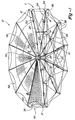
- the antenna reflector 10 includes a wire woven mesh 40 fastened to a telescoping deployable support assembly 11. More particularly, the support assembly 11 includes a plurality of telescoping radial extending ribs 12 which provide structural support. Each of the of the ribs 12 includes an inner rib 14 and an outer rib 16. The inner ribs 14 each include a first end 18 and a second end 20. Similarly, each of the outer ribs 16 includes a first end 22 and a second end 24. The inner and outer ribs 14 and 16 are folded. And the strut members 26 fold against outer ribs 16.
- Each of the first ends 18 of the inner ribs 14 are connected to a common cylindrical shaped hub 28.
- the hub 28 has an opening 30 disposed therein for accepting a telescoping cylindrical-shaped mast 32.
- Each of the plurality of telescoping radial extending ribs 12 includes a pair of front and rear spreader bars 34 and 36 located at the second end 24 thereof.
- the support assembly 11 of the reflector 10 further includes a plurality of wires or guylines 38 which further define and maintain the shape of the reflector 10.
- the plurality of guylines 38 substantially increase the structural stiffness and form a stable wire truss structure to which the wire mesh surface 40 is fastened.
- each gore 42 includes a plurality of precisely interconnected surface setting guylines 38 which span the plurality of telescoping radial extending ribs 12 and the spreader bars 34 and 36.
- the surface setting guylines 38 form a substantially parabolic-shaped support structure to which the wire mesh material 40 is fastened.
- the antenna reflector 10 is deployable in that it may be fully deployed as shown in Fig. 1, or the plurality of telescoping radial extending ribs 12 and spreader bars 34 and 36 may be collapsed, folded and thereby stowed as shown in Fig. 2.
- each of the inner and outer ribs 14 and 16 and spreader bars 34 and 36 are collapsed and fold up against the collapsed mast 32.
- the inner and outer ribs 14 and 16 are folded.
- the strut members 26 fold against outer ribs 16.
- the antenna reflector 10 may be stowed within a small space when not in use, and this is an important feature for space related applications especially where medium launch vehicles are employed due to reduced payload capabilities of such vehicles.
- each of the inner ribs 14 include inner tube segments 44 that telescope outward from within outer tube segments 46.
- each of the outer ribs 16 include inner tube segments 48 that telescope outward from within outer tube segments 49.
- Each of the inner and outer ribs 14 and 16 include latching mechanisms 50 which secure the ribs 12 in the extended position. The operation of the latching mechanisms 50 will be discussed in detail below.
- the ability of the antenna reflector 10 to telescope from the stowed non-extended position illustrated in Fig. 1, to the extended position illustrated in Fig. 2, reduces the stowed height of the antenna reflector 10 without increasing the stowed diameter. As discussed above, this is an important feature for space related applications where the size of payloads are limited.
- Figs. 4A through 4F schematically illustrate the deployment sequence for deploying the antenna reflector 10.
- the hub 28 and the mast 32 employ a motor coupled to a cable drive (not shown) which when actuated in conjunction with various pulleys and the guylines 38, drive the hub 28 and the mast 32.
- Fig. 4A illustrates the antenna reflector 10 in the stowed non-extended position.
- Each of the telescoping radially extending ribs 12 are in a collapsed stowed non-extended position, and the hub member 28 is located at a lower end 52 of the mast 32 which is also collapsed.
- the mast 32 as well as the ribs 12 telescope or extend upwards to the extended position.
- Fig. 4C thereafter, as illustrated in Fig. 4C, as the hub 28 moves along the mast 32 towards a top end 54, the plurality of radially extending ribs 12 release and rotate outward from the mast 32 and thereby partially unfold. As shown in Fig. 4D, the hub 28 continues to move along the mast 32 such that the outer ribs 16 release and rotate about the pivot arm 76 away from the inner ribs 14. Turning to Fig. 4E, as the hub 28 continues to move along the mast 32, the spreader bars 34 and 36 as well as the strut members 26 are released and thereafter extend outward from the ribs 12.
- the outer rib members 16 complete the a final rotation outward from the inner ribs 14 to a final deployed position.
- the antenna reflector 10 is fully deployed and produces a sufficient load to provide an appropriate shape for the mesh surface 40.
- slack in the various guylines 38 is taken up so as to produce a rigid support assembly for the mesh surface 40.
- FIG. 5 an exploded perspective view of a representative latching mechanism 50 for the inner ribs 14 or the outer ribs 16 is illustrated.
- the latching mechanism 50 includes an end fitting 56 and an end cap 58 which are aligned by locating pins 59 and coupled by a plurality of fasteners 60.
- the end fitting 56 is coupled to one of the outer tube segments 48.
- the latching mechanisms 50 operate in a similar manner in conjunction with the inner ribs 14.
- the latching mechanism 50 further includes three pawl latches 66 and a c-spring member 68.
- a telescoping tube member 72 and a guide tube member 70 facilitate the telescoping of the inner tube segment 48 from within the outer tube segments 49 during the above-discussed deployment sequence.
- the telescoping tube member 72 includes integral guide rails 73 upon which the latches 66 slide.
- the guide tube member 70 includes raised portions 74 and 75 between which the latches 66 are received when the outer rib 16 telescopes from the stowed non-extended position into the extended position illustrated in FIG. 2.
- FIGS. 6A through 6B illustrate the latching sequence that occurs during the deployment sequence as discussed above in conjunction with Figs. 4A through 4F.
- FIG. 6A one of the outer ribs 16 is shown in a non-extended position with the latches 66 and c-spring member 68 preloaded within the end fitting 56.
- FIGS. 6B and 6C during the telescoping sequence, the inner tube segment 48 and telescoping tube member 72 and guide tube member 70 telescope outward in a direction indicated by arrow A from within outer tube member 49.
- FIG. 6D prior to reaching the deployed position, the c-spring 68 forces the latches 66 into the area between the raised portions 74 and 75.
- FIG. 6E the inner tube segment 48 and the tube member 70 continue to telescope outward until the latches 66 bottom out against raised portion 75 as shown in Figure 6F.
- Figure 6G shows tension from the guylines 38 reverse the direction of travel of the inner tube segment 48 and tube member 70 until the latches 66 bottom out and rest against the raised portion 74.
- the outer rib 16 is securely locked in the deployed extended position.
- a wedge shaped tool (not shown) is inserted within openings 81 in the end cap 58 for engaging ramp shaped slots 79 in the latches 66. This forces the latches 66 and c-spring 68 away from the surface of the tube member 70 allowing ribs 14 and 16 the raised portions 74 and 75 to slide past the latches 66. This allows the rib 16 to be collapsed into stowed non-extended position.
- Fig. 7 illustrates in detail one of the gores 42 of the antenna reflector 10.
- the hub 28 when deployed, the hub 28 is positioned near the top end 54 of the mast 32.
- the gore 42 includes a wire truss structure having a plurality of surface settings guylines 38 which are connected and remain under tension between a pair of telescoping radially extending ribs 12a and 12b to define a front and rear surface.
- the various surface setting guylines 38 include a pair of front radial catenary guylines 80a and 80b which extend from an upper or front position near the hub 28 rearwardly outward toward the tip of the spreader bars 34a and 34b.
- a first pair of rear radial catenary guylines 82a and 82b are also included which extend radially outward about the rear surface of the gore 42 from the hub 28 to the second ends 20a and 20b of inner ribs 14a and 14b.
- a second pair of rear radial catenary guylines 84a and 84b are included which extend radially outward about the rear surface from the first ends 22a and 22b of the outer ribs 16a and 16b to the second ends 24a and 24b of the outer ribs 16a and 16b.
- the rear radial catenary guylines 82a and 82b as well as 84a and 84b are essentially located in the rear surface plane of the gore 42 directly below the front, radial catenary guylines 80a and 80b on the front surface of the gore 42.
- a plurality of front cross-catenary guylines 86 are connected between the pair of front radial catenary guylines 80a and 80b on the front surface of the gore 42.
- a plurality of rear-cross catenary guylines 88 are connected across the plurality of rear radial catenary guylines 82a and 82b as well as across rear radial catenary guylines 84a and 84b on the rear surface of the gore 42.
- a plurality of drop ties 90 are connected between the front radial catenary guylines 80a and 80b and the rear radial catenary guylines 82a, 82b, 84a and 84b.
- a plurality of drop ties 90 are connected between the front cross-catenary guylines 86 and the rear cross-catenary guylines 88.
- the front radial catenary guylines 80a and 80b and the front cross-catenary guylines 86 form the front surface of the gore 42.
- the rear cross-catenary guylines 88 and rear radial catenary guylines 82a, 82b, 84a and 84b form the rear surface of the gore 42 which is connected to the front surface with the plurality of drop ties 90.
- the wire woven mesh material 40 is then essentially fastened to the front surface of each of the plurality of gores 42 to form the antenna reflector 10.
- the conglomerate of surface setting guylines 38 thereby operate to provide the precise antenna reflector surface setting necessary for minimizing various reflector losses by controlling the shape or contour in each gore 42.
- FIGs. 1 and 8 illustrate the location of one of the integral fitting assemblies 100.
- a front radial catenary guyline 80 extends through the integral fitting 100 and the front-cross catenary guylines 86 are coupled to one another via the integral fitting assembly 100.
- the wire woven mesh material 40 from two adjoining gores 42 are connected to the front surface of the reflector 10 with radially extending strip members 102a and 102b.
- the members 102a and 102b are made from a flexible material such as Nomex fabric and are located at the intersection of the adjoining gores 42.
- the front radial catenary guyline 80 extends through sleeves 108 in the radial strip 102a and sleeves 122 in radial strip 102b. The radial strips are in turn secured to the mesh material 40 of the gores 42.
- the wire woven mesh material 40 is a highly reflective gold plated molybdenum wire woven into an approximately 28 to 32 openings-per-inch mesh knit pattern. This wire woven mesh material 40 provides for ultra-low signal loss at high frequencies. The very low signal loss mesh surface allows for a wider spacing of the drop ties 90 while maintaining minimal signal loss requirements. It is believed that mesh knit patterns having less than 28 openings-per-inch are disadvantageous because the spacing of the drop ties 90 would not be practical, while patterns having greater than 32 openings-per-inch are likewise not preferred because of high mesh stiffness.
- radial strips 102a and 102b to connect the gores 42 allows for the folding of the inner and outer ribs 14 and 16 in order to stow the reflector 10 and allows for the deployment scheme illustrated in Figs. 4A - 4F to be utilized.
- Previous antenna reflectors included rigid radial strip members which would not permit such folding and unfolding of the antenna reflector which, in turn, increased the storage volume of such previous reflectors.
- Fig. 9 is a cutaway view of a section of the radial strip 102a.
- the radial strip 102a includes a sleeve portions 108a and 108b with a notch 110 located therebetween.
- the mesh surface 40 (not shown) is secured between an overlap section 112 including portions 114 and 116.
- a black polyurethane adhesive 120 is located between the portions 114 and 116 as well as around the edges of the notch portion 110.
- the telescoping deployable antenna reflector 10 has a reduced stowed height and diameter when compared to prior antenna reflectors having a same size aperture.
- An additional advantage of the present invention is that the antenna reflector 10 may be folded about itself due to the use of the flexible radial strip members which again allows the stowed volume of the antenna reflector 10 to be minimized.
Landscapes
- Physics & Mathematics (AREA)
- Electromagnetism (AREA)
- Aerials With Secondary Devices (AREA)
- Details Of Aerials (AREA)
Applications Claiming Priority (2)
| Application Number | Priority Date | Filing Date | Title |
|---|---|---|---|
| US08/647,524 US5864324A (en) | 1996-05-15 | 1996-05-15 | Telescoping deployable antenna reflector and method of deployment |
| US647524 | 1996-05-15 |
Publications (2)
| Publication Number | Publication Date |
|---|---|
| EP0807991A1 true EP0807991A1 (fr) | 1997-11-19 |
| EP0807991B1 EP0807991B1 (fr) | 2000-07-12 |
Family
ID=24597310
Family Applications (1)
| Application Number | Title | Priority Date | Filing Date |
|---|---|---|---|
| EP97103734A Expired - Lifetime EP0807991B1 (fr) | 1996-05-15 | 1997-03-06 | Réflecteur téléscopique déployable pour antenne et procédé de déploiement du réflecteur |
Country Status (3)
| Country | Link |
|---|---|
| US (1) | US5864324A (fr) |
| EP (1) | EP0807991B1 (fr) |
| DE (1) | DE69702480T2 (fr) |
Cited By (21)
| Publication number | Priority date | Publication date | Assignee | Title |
|---|---|---|---|---|
| EP0959524A1 (fr) * | 1998-05-18 | 1999-11-24 | TRW Inc. | Réflecteur ayant une structure périmétrique en treillis pliable |
| EP1077506A1 (fr) * | 1999-06-18 | 2001-02-21 | TRW Inc. | Système d'arrimage compact de réflecteurs ayant une structure périmétrique en treillis pliable |
| FR2821490A1 (fr) * | 2001-02-23 | 2002-08-30 | Lacroix Soc E | Reflecteur electromagnetique deployable |
| FR2821488A1 (fr) * | 2001-02-23 | 2002-08-30 | Lacroix Soc E | Reflecteur electromagnetique deployable |
| FR2821491A1 (fr) * | 2001-02-23 | 2002-08-30 | Lacroix Soc E | Reflecteur electromagnetique deployable |
| WO2002069441A1 (fr) * | 2001-02-23 | 2002-09-06 | Etienne Lacroix Tous Artifices S.A. | Reflecteur electromagnetique deployable |
| GB2465030A (en) * | 2008-11-11 | 2010-05-12 | Francis & Lewis Internat Ltd | Articulate frame structure for anchoring and supporting a mast. |
| RU2447550C2 (ru) * | 2010-05-04 | 2012-04-10 | Открытое акционерное общество "Информационные спутниковые системы" имени академика М.Ф. Решетнева" | Зонтичная антенна космического аппарата |
| RU2449437C1 (ru) * | 2010-10-04 | 2012-04-27 | Открытое акционерное общество "Информационные спутниковые системы" имени академика М.Ф. Решетнева" | Развертываемый крупногабаритный рефлектор космического аппарата и способ его изготовления |
| CN102904001A (zh) * | 2012-10-26 | 2013-01-30 | 哈尔滨工业大学 | 可折展模块及采用该可折展模块的曲面桁架天线支撑机构 |
| FR3014417A1 (fr) * | 2013-12-10 | 2015-06-12 | Eads Europ Aeronautic Defence | Nouvelle architecture de vehicule spatial |
| RU2583420C1 (ru) * | 2014-12-31 | 2016-05-10 | Акционерное общество "Научно-производственная корпорация "Космические системы мониторинга, информационно-управляющие и электромеханические комплексы" имени А.Г. Иосифьяна" (АО "Корпорация "ВНИИЭМ") | Рама радиолокационной антенны космического аппарата |
| CN106159409A (zh) * | 2016-07-19 | 2016-11-23 | 中国科学院国家空间科学中心 | 一种空间薄壁管状伸展臂展开装置 |
| CN106299587A (zh) * | 2016-08-24 | 2017-01-04 | 西安电子科技大学 | 基于剪刀式桁架结构的静电成形薄膜反射面天线 |
| CN108183304A (zh) * | 2017-12-28 | 2018-06-19 | 赵方韬 | 一种基于主轴的可展开卫星天线桁架结构 |
| EA030720B1 (ru) * | 2015-06-17 | 2018-09-28 | Акционерное общество "Информационные спутниковые системы" имени академика М.Ф. Решетнёва" | Зонтичная антенна космического аппарата |
| CN108666733A (zh) * | 2018-05-15 | 2018-10-16 | 西安空间无线电技术研究所 | 一种网状天线网面管理机构及管理方法 |
| CN110247150A (zh) * | 2018-03-09 | 2019-09-17 | 刘方圆 | 一种可展开卫星天线桁架结构 |
| EP3614487A1 (fr) * | 2018-08-21 | 2020-02-26 | Eagle Technology, LLC | Structure de support de fissure pliée pour antenne de réflecteur à zéro sur-étirement |
| CN113258249A (zh) * | 2021-05-18 | 2021-08-13 | 上海宇航系统工程研究所 | 一种在轨超大型可展开空间结构系统 |
| US11791563B1 (en) * | 2022-04-24 | 2023-10-17 | Xidian University | Deployable mesh antenna based on dome-type tensegrity |
Families Citing this family (37)
| Publication number | Priority date | Publication date | Assignee | Title |
|---|---|---|---|---|
| WO1998038695A1 (fr) * | 1997-02-27 | 1998-09-03 | Sakimura Corporation | Reflecteur pliable facile a manier |
| US6219009B1 (en) * | 1997-06-30 | 2001-04-17 | Harris Corporation | Tensioned cord/tie attachment of antenna reflector to inflatable radial truss support structure |
| US6243053B1 (en) * | 1999-03-02 | 2001-06-05 | Trw Inc. | Deployable large antenna reflector structure |
| US6618025B2 (en) | 1999-06-11 | 2003-09-09 | Harris Corporation | Lightweight, compactly deployable support structure with telescoping members |
| US6313811B1 (en) * | 1999-06-11 | 2001-11-06 | Harris Corporation | Lightweight, compactly deployable support structure |
| US6624796B1 (en) | 2000-06-30 | 2003-09-23 | Lockheed Martin Corporation | Semi-rigid bendable reflecting structure |
| ITBO20020012A1 (it) * | 2002-01-11 | 2003-07-11 | Consiglio Nazionale Ricerche | Apparecchiatura per il rilevamento di radiazioni elettromagnetiche , in particolare per applicazioni radioastronomiche |
| US7211722B1 (en) | 2002-04-05 | 2007-05-01 | Aec-Able Engineering Co., Inc. | Structures including synchronously deployable frame members and methods of deploying the same |
| US20080155919A1 (en) * | 2006-12-29 | 2008-07-03 | Petros Keshishian | Method of manufacturing composite structural panels and using superimposed truss members with same |
| US7686255B2 (en) * | 2007-08-28 | 2010-03-30 | Raytheon Company | Space vehicle having a payload-centric configuration |
| US7748376B2 (en) | 2007-10-31 | 2010-07-06 | Bender William H | Solar collector stabilized by cables and a compression element |
| US20090133355A1 (en) * | 2007-11-27 | 2009-05-28 | Mehran Mobrem | Deployable Membrane Structure |
| US7710348B2 (en) * | 2008-02-25 | 2010-05-04 | Composite Technology Development, Inc. | Furlable shape-memory reflector |
| US8259033B2 (en) * | 2009-01-29 | 2012-09-04 | Composite Technology Development, Inc. | Furlable shape-memory spacecraft reflector with offset feed and a method for packaging and managing the deployment of same |
| US9281569B2 (en) | 2009-01-29 | 2016-03-08 | Composite Technology Development, Inc. | Deployable reflector |
| US8508430B2 (en) * | 2010-02-01 | 2013-08-13 | Harris Corporation | Extendable rib reflector |
| US9550584B1 (en) * | 2010-09-30 | 2017-01-24 | MMA Design, LLC | Deployable thin membrane apparatus |
| WO2012116366A2 (fr) * | 2011-02-25 | 2012-08-30 | Utah State University Research Foundation | Télescope déployable à pétales multiples |
| US9366853B2 (en) | 2011-02-25 | 2016-06-14 | Utah State University Research Foundation | Multiple petal deployable telescope |
| AT513454B1 (de) * | 2012-09-10 | 2014-07-15 | Ahmed Adel | Parabolrinnenkollektor mit verstellbaren Parametern |
| US9755318B2 (en) | 2014-01-09 | 2017-09-05 | Northrop Grumman Systems Corporation | Mesh reflector with truss structure |
| US9484636B2 (en) * | 2014-02-26 | 2016-11-01 | Northrop Grumman Systesms Corportion | Mesh reflector with truss structure |
| US10283835B2 (en) * | 2015-09-25 | 2019-05-07 | MMA Design, LLC | Deployable structure for use in establishing a reflectarray antenna |
| US9608333B1 (en) * | 2015-12-07 | 2017-03-28 | Harris Corporation | Scalable high compaction ratio mesh hoop column deployable reflector system |
| US10811777B1 (en) | 2017-05-03 | 2020-10-20 | United States Of America As Represented By The Secretary Of The Air Force | Deployable origami antenna array with tunable directivity |
| WO2020036623A2 (fr) * | 2018-01-08 | 2020-02-20 | Umbra Lab, Inc. | Réflecteur à nervure pliable articulé pour concentrer un rayonnement |
| US10516216B2 (en) | 2018-01-12 | 2019-12-24 | Eagle Technology, Llc | Deployable reflector antenna system |
| US10418712B1 (en) | 2018-11-05 | 2019-09-17 | Eagle Technology, Llc | Folded optics mesh hoop column deployable reflector system |
| US10811759B2 (en) | 2018-11-13 | 2020-10-20 | Eagle Technology, Llc | Mesh antenna reflector with deployable perimeter |
| US11139549B2 (en) | 2019-01-16 | 2021-10-05 | Eagle Technology, Llc | Compact storable extendible member reflector |
| US10797400B1 (en) | 2019-03-14 | 2020-10-06 | Eagle Technology, Llc | High compaction ratio reflector antenna with offset optics |
| US11319093B2 (en) | 2019-05-06 | 2022-05-03 | Eagle Technology, Llc | Deployment mechanism for reflector antenna system |
| US11784415B2 (en) * | 2019-09-24 | 2023-10-10 | Airbus Defence and Space S.A. | Deployable assembly for antennas |
| US11283183B2 (en) | 2019-09-25 | 2022-03-22 | Eagle Technology, Llc | Deployable reflector antenna systems |
| CN113764899B (zh) * | 2021-08-04 | 2022-11-18 | 同济大学 | 一种肋网式可展开天线的网面安装方法 |
| US11949161B2 (en) | 2021-08-27 | 2024-04-02 | Eagle Technology, Llc | Systems and methods for making articles comprising a carbon nanotube material |
| US11901629B2 (en) | 2021-09-30 | 2024-02-13 | Eagle Technology, Llc | Deployable antenna reflector |
Citations (6)
| Publication number | Priority date | Publication date | Assignee | Title |
|---|---|---|---|---|
| US4352113A (en) * | 1980-07-11 | 1982-09-28 | Societe Nationale Industrielle Aerospatiale | Foldable antenna reflector |
| US4608571A (en) * | 1981-03-26 | 1986-08-26 | Luly Robert A | Collapsible parabolic reflector |
| JPS6388903A (ja) * | 1986-10-02 | 1988-04-20 | Nippon Telegr & Teleph Corp <Ntt> | 3次元トラス宇宙構造体 |
| EP0290729A2 (fr) * | 1987-05-14 | 1988-11-17 | Mitsubishi Denki Kabushiki Kaisha | Structure en treillis déployable et module pour celà |
| JPH02237202A (ja) * | 1989-03-09 | 1990-09-19 | Mitsubishi Electric Corp | 展開型パラボラアンテナ |
| JPH04288705A (ja) * | 1991-03-18 | 1992-10-13 | Uchu Tsushin Kiso Gijutsu Kenkyusho:Kk | ホーンアンテナ |
Family Cites Families (36)
| Publication number | Priority date | Publication date | Assignee | Title |
|---|---|---|---|---|
| US3290688A (en) * | 1962-06-11 | 1966-12-06 | Univ Ohio State Res Found | Backward angle travelling wave wire mesh antenna array |
| US3217328A (en) * | 1963-03-08 | 1965-11-09 | Electro Optical Systems Inc | Antenna with wire mesh reflector collapsing in a pinwheel manner |
| US3397399A (en) * | 1966-02-07 | 1968-08-13 | Goodyear Aerospace Corp | Collapsible dish reflector |
| US3576566A (en) * | 1966-10-31 | 1971-04-27 | Hughes Aircraft Co | Closed loop antenna reflector supporting structure |
| US3496687A (en) * | 1967-03-22 | 1970-02-24 | North American Rockwell | Extensible structure |
| US3618111A (en) * | 1967-04-28 | 1971-11-02 | Gen Dynamics Corp | Expandable truss paraboloidal antenna |
| US3509576A (en) * | 1967-12-04 | 1970-04-28 | Lockheed Aircraft Corp | Collapsible parabolic antenna formed of a series of truncated fabric cones |
| US3530469A (en) * | 1968-06-26 | 1970-09-22 | North American Rockwell | Energy impingement device |
| US3717879A (en) * | 1968-12-03 | 1973-02-20 | Neotec Corp | Collapsible reflector |
| US3635547A (en) * | 1969-12-08 | 1972-01-18 | Westinghouse Electric Corp | Reflector construction |
| US3631505A (en) * | 1970-03-23 | 1971-12-28 | Goodyear Aerospace Corp | Expandable antenna |
| US3707720A (en) * | 1970-10-02 | 1972-12-26 | Westinghouse Electric Corp | Erectable space antenna |
| US3855598A (en) * | 1970-10-23 | 1974-12-17 | Hughes Aircraft Co | Mesh articles particularly for use as reflectors of electromagnetic waves |
| US3780375A (en) * | 1971-11-26 | 1973-12-18 | North American Rockwell | Deployable parabolic antennas |
| US3982248A (en) * | 1974-07-01 | 1976-09-21 | Trw Inc. | Compliant mesh structure for collapsible reflector |
| US3987457A (en) * | 1974-08-05 | 1976-10-19 | Trw Inc. | Variable property wire mesh antenna structure |
| US4001836A (en) * | 1975-02-28 | 1977-01-04 | Trw Inc. | Parabolic dish and method of constructing same |
| US4191604A (en) * | 1976-01-07 | 1980-03-04 | General Dynamics Corporation Pomona Division | Method of constructing three-dimensionally curved, knit wire reflector |
| US4151534A (en) * | 1977-09-14 | 1979-04-24 | Bond Orville R | Antenna telescoping tower |
| US4242686A (en) * | 1978-04-24 | 1980-12-30 | General Dynamics Corporation, Pomona Division | Three-dimensionally curved, knit wire electromagnetic wave reflector |
| US4176360A (en) * | 1978-09-18 | 1979-11-27 | The United States Of America As Represented By The Administrator Of The National Aeronautics And Space Administration | Antenna deployment mechanism for use with a spacecraft |
| US4527166A (en) * | 1981-03-26 | 1985-07-02 | Luly Robert A | Lightweight folding parabolic reflector and antenna system |
| DE3124907A1 (de) * | 1981-06-25 | 1983-01-13 | Messerschmitt-Bölkow-Blohm GmbH, 8000 München | "entfaltbarer antennen-netzreflektor" |
| US4683475A (en) * | 1981-07-02 | 1987-07-28 | Luly Robert A | Folding dish reflector |
| US4475111A (en) * | 1982-02-16 | 1984-10-02 | General Electric Company | Portable collapsing antenna |
| US4398724A (en) * | 1982-02-19 | 1983-08-16 | Wilson Wayne D | Volleyball net touch detecting and indicating system |
| US4549187A (en) * | 1982-04-05 | 1985-10-22 | Lockheed Missiles & Space Company, Inc. | Metallic coated and lubricated amorphous silica yarn used as a mesh antenna reflector |
| US4475323A (en) * | 1982-04-30 | 1984-10-09 | Martin Marietta Corporation | Box truss hoop |
| DE3338937A1 (de) * | 1983-10-27 | 1985-05-09 | Messerschmitt-Bölkow-Blohm GmbH, 8012 Ottobrunn | Entfaltbarer antennen-netzreflektor |
| US4587526A (en) * | 1984-05-02 | 1986-05-06 | The United States Of America As Represented By The Administrator Of The National Aeronautics And Space Administration | Latching mechanism for deployable/re-stowable columns useful in satellite construction |
| DE3423526A1 (de) * | 1984-06-26 | 1986-01-02 | Messerschmitt-Bölkow-Blohm GmbH, 8012 Ottobrunn | Entfaltbarer und wiedereinfaltbarer antennenreflektor |
| US5104211A (en) * | 1987-04-09 | 1992-04-14 | Harris Corp. | Splined radial panel solar concentrator |
| US4811033A (en) * | 1987-11-10 | 1989-03-07 | National Aeronautics And Space Administration | Antenna surface contour control system |
| US4975713A (en) * | 1988-04-11 | 1990-12-04 | Modublox & Co., Inc. | Mobile mesh antenna |
| JPH01305607A (ja) * | 1988-06-02 | 1989-12-08 | Nippon Telegr & Teleph Corp <Ntt> | 展開メッシュアンテナ |
| US5334990A (en) * | 1990-03-26 | 1994-08-02 | K-Star International Corp. | Ku-band satellite dish antenna |
-
1996
- 1996-05-15 US US08/647,524 patent/US5864324A/en not_active Expired - Fee Related
-
1997
- 1997-03-06 EP EP97103734A patent/EP0807991B1/fr not_active Expired - Lifetime
- 1997-03-06 DE DE69702480T patent/DE69702480T2/de not_active Expired - Fee Related
Patent Citations (6)
| Publication number | Priority date | Publication date | Assignee | Title |
|---|---|---|---|---|
| US4352113A (en) * | 1980-07-11 | 1982-09-28 | Societe Nationale Industrielle Aerospatiale | Foldable antenna reflector |
| US4608571A (en) * | 1981-03-26 | 1986-08-26 | Luly Robert A | Collapsible parabolic reflector |
| JPS6388903A (ja) * | 1986-10-02 | 1988-04-20 | Nippon Telegr & Teleph Corp <Ntt> | 3次元トラス宇宙構造体 |
| EP0290729A2 (fr) * | 1987-05-14 | 1988-11-17 | Mitsubishi Denki Kabushiki Kaisha | Structure en treillis déployable et module pour celà |
| JPH02237202A (ja) * | 1989-03-09 | 1990-09-19 | Mitsubishi Electric Corp | 展開型パラボラアンテナ |
| JPH04288705A (ja) * | 1991-03-18 | 1992-10-13 | Uchu Tsushin Kiso Gijutsu Kenkyusho:Kk | ホーンアンテナ |
Non-Patent Citations (5)
| Title |
|---|
| D'ADDARIO L R: "MICROWAVE TECHNOLOGY INNOVATIONS IN ORBITING VLBI", 1 June 1992, INTERNATIONAL MICROWAVE SYMPOSIUM DIGEST (MTT-S), ALBUQUERQUE, JUNE 1 - 5, 1992, VOL. 3, PAGE(S) 1375 - 1378, REID D W, XP000344430 * |
| PATENT ABSTRACTS OF JAPAN vol. 012, no. 324 (E - 653) 2 September 1988 (1988-09-02) * |
| PATENT ABSTRACTS OF JAPAN vol. 014, no. 553 (E - 1010) 7 December 1990 (1990-12-07) * |
| PATENT ABSTRACTS OF JAPAN vol. 017, no. 097 (E - 1326) 25 February 1993 (1993-02-25) * |
| TAKANO T ET AL: "A TENSION-TRUSS DEPLOYABLE ANTENNA FOR SPACE-USE AND ITS OBTAINABLE CHARACTERISTICS", DIGEST OF THE ANTENNAS AND PROPAGATION SOCIETY INTERNATIONAL SYMPOSIUM, SEATTLE, WA., JUNE 19 - 24, 1994, vol. 2, 19 June 1994 (1994-06-19), INSTITUTE OF ELECTRICAL AND ELECTRONICS ENGINEERS, pages 878 - 881, XP000545557 * |
Cited By (32)
| Publication number | Priority date | Publication date | Assignee | Title |
|---|---|---|---|---|
| EP0959524A1 (fr) * | 1998-05-18 | 1999-11-24 | TRW Inc. | Réflecteur ayant une structure périmétrique en treillis pliable |
| EP1077506A1 (fr) * | 1999-06-18 | 2001-02-21 | TRW Inc. | Système d'arrimage compact de réflecteurs ayant une structure périmétrique en treillis pliable |
| US6225965B1 (en) | 1999-06-18 | 2001-05-01 | Trw Inc. | Compact mesh stowage for deployable reflectors |
| FR2821490A1 (fr) * | 2001-02-23 | 2002-08-30 | Lacroix Soc E | Reflecteur electromagnetique deployable |
| FR2821488A1 (fr) * | 2001-02-23 | 2002-08-30 | Lacroix Soc E | Reflecteur electromagnetique deployable |
| FR2821491A1 (fr) * | 2001-02-23 | 2002-08-30 | Lacroix Soc E | Reflecteur electromagnetique deployable |
| WO2002069441A1 (fr) * | 2001-02-23 | 2002-09-06 | Etienne Lacroix Tous Artifices S.A. | Reflecteur electromagnetique deployable |
| US6791486B2 (en) | 2001-02-23 | 2004-09-14 | Etienne Lacroix Tous Artifices S.A. | Unfoldable electromagnetic reflector |
| EP1458052A1 (fr) * | 2001-02-23 | 2004-09-15 | Etienne Lacroix - Tous Artifices Sa | Reflecteur electromagnetique deployable |
| GB2465030A (en) * | 2008-11-11 | 2010-05-12 | Francis & Lewis Internat Ltd | Articulate frame structure for anchoring and supporting a mast. |
| RU2447550C2 (ru) * | 2010-05-04 | 2012-04-10 | Открытое акционерное общество "Информационные спутниковые системы" имени академика М.Ф. Решетнева" | Зонтичная антенна космического аппарата |
| RU2449437C1 (ru) * | 2010-10-04 | 2012-04-27 | Открытое акционерное общество "Информационные спутниковые системы" имени академика М.Ф. Решетнева" | Развертываемый крупногабаритный рефлектор космического аппарата и способ его изготовления |
| CN102904001A (zh) * | 2012-10-26 | 2013-01-30 | 哈尔滨工业大学 | 可折展模块及采用该可折展模块的曲面桁架天线支撑机构 |
| CN106061843A (zh) * | 2013-12-10 | 2016-10-26 | 空客集团有限公司 | 新型航天器结构 |
| WO2015086970A1 (fr) * | 2013-12-10 | 2015-06-18 | Airbus Group Sas | Nouvelle architecture de véhicule spatial |
| FR3014417A1 (fr) * | 2013-12-10 | 2015-06-12 | Eads Europ Aeronautic Defence | Nouvelle architecture de vehicule spatial |
| CN106061843B (zh) * | 2013-12-10 | 2018-04-03 | 空客集团有限公司 | 航天器结构 |
| US10450092B2 (en) | 2013-12-10 | 2019-10-22 | Airbus Group Sas | Spacecraft architecture having torus-shaped solar concentrator |
| RU2583420C1 (ru) * | 2014-12-31 | 2016-05-10 | Акционерное общество "Научно-производственная корпорация "Космические системы мониторинга, информационно-управляющие и электромеханические комплексы" имени А.Г. Иосифьяна" (АО "Корпорация "ВНИИЭМ") | Рама радиолокационной антенны космического аппарата |
| EA030720B1 (ru) * | 2015-06-17 | 2018-09-28 | Акционерное общество "Информационные спутниковые системы" имени академика М.Ф. Решетнёва" | Зонтичная антенна космического аппарата |
| CN106159409A (zh) * | 2016-07-19 | 2016-11-23 | 中国科学院国家空间科学中心 | 一种空间薄壁管状伸展臂展开装置 |
| CN106159409B (zh) * | 2016-07-19 | 2019-01-22 | 中国科学院国家空间科学中心 | 一种空间薄壁管状伸展臂展开装置 |
| CN106299587A (zh) * | 2016-08-24 | 2017-01-04 | 西安电子科技大学 | 基于剪刀式桁架结构的静电成形薄膜反射面天线 |
| CN106299587B (zh) * | 2016-08-24 | 2019-03-29 | 西安电子科技大学 | 基于剪刀式桁架结构的静电成形薄膜反射面天线 |
| CN108183304A (zh) * | 2017-12-28 | 2018-06-19 | 赵方韬 | 一种基于主轴的可展开卫星天线桁架结构 |
| CN108183304B (zh) * | 2017-12-28 | 2019-01-08 | 赵方韬 | 一种基于主轴的可展开卫星天线桁架结构 |
| CN110247150A (zh) * | 2018-03-09 | 2019-09-17 | 刘方圆 | 一种可展开卫星天线桁架结构 |
| CN108666733A (zh) * | 2018-05-15 | 2018-10-16 | 西安空间无线电技术研究所 | 一种网状天线网面管理机构及管理方法 |
| EP3614487A1 (fr) * | 2018-08-21 | 2020-02-26 | Eagle Technology, LLC | Structure de support de fissure pliée pour antenne de réflecteur à zéro sur-étirement |
| US10707552B2 (en) | 2018-08-21 | 2020-07-07 | Eagle Technology, Llc | Folded rib truss structure for reflector antenna with zero over stretch |
| CN113258249A (zh) * | 2021-05-18 | 2021-08-13 | 上海宇航系统工程研究所 | 一种在轨超大型可展开空间结构系统 |
| US11791563B1 (en) * | 2022-04-24 | 2023-10-17 | Xidian University | Deployable mesh antenna based on dome-type tensegrity |
Also Published As
| Publication number | Publication date |
|---|---|
| EP0807991B1 (fr) | 2000-07-12 |
| US5864324A (en) | 1999-01-26 |
| DE69702480D1 (de) | 2000-08-17 |
| DE69702480T2 (de) | 2000-12-14 |
Similar Documents
| Publication | Publication Date | Title |
|---|---|---|
| US5864324A (en) | Telescoping deployable antenna reflector and method of deployment | |
| US4475323A (en) | Box truss hoop | |
| US7009578B2 (en) | Deployable antenna with foldable resilient members | |
| US6028570A (en) | Folding perimeter truss reflector | |
| US6202379B1 (en) | Modular deployable antenna | |
| US3717879A (en) | Collapsible reflector | |
| US4677803A (en) | Deployable geodesic truss structure | |
| WO2014127813A1 (fr) | Structure de support déployable | |
| JP2731108B2 (ja) | 展開型アンテナ反射器及びその展開方法 | |
| US6323827B1 (en) | Micro fold reflector | |
| US10516216B2 (en) | Deployable reflector antenna system | |
| US4529277A (en) | Foldable reflector | |
| US5635946A (en) | Stowable, deployable, retractable antenna | |
| US7138960B2 (en) | Deployable electromagnetic concentrator | |
| JP4876941B2 (ja) | 展開型アンテナ | |
| US20190144139A1 (en) | Large aperture unfurlable reflector deployed by a telescopic boom | |
| US6266030B1 (en) | Flexible self-actuated structure and associated method | |
| US4783936A (en) | Space rail for large space systems | |
| US11319093B2 (en) | Deployment mechanism for reflector antenna system | |
| CN107196065B (zh) | 大型可展开固面天线 | |
| JP7459237B2 (ja) | アンテナ用展開式アセンブリ | |
| EP3923412B1 (fr) | Systèmes et procédés permettant de fournir des antennes ayant des positions décalés couplés mécaniquement | |
| JP2642591B2 (ja) | 展開型アンテナ反射鏡 | |
| CN114503361B (zh) | 天线可展开组件 | |
| RU2795105C1 (ru) | Развертываемый узел для антенн |
Legal Events
| Date | Code | Title | Description |
|---|---|---|---|
| PUAI | Public reference made under article 153(3) epc to a published international application that has entered the european phase |
Free format text: ORIGINAL CODE: 0009012 |
|
| AK | Designated contracting states |
Kind code of ref document: A1 Designated state(s): DE FR GB IT |
|
| 17P | Request for examination filed |
Effective date: 19971211 |
|
| 17Q | First examination report despatched |
Effective date: 19980804 |
|
| GRAG | Despatch of communication of intention to grant |
Free format text: ORIGINAL CODE: EPIDOS AGRA |
|
| GRAG | Despatch of communication of intention to grant |
Free format text: ORIGINAL CODE: EPIDOS AGRA |
|
| GRAH | Despatch of communication of intention to grant a patent |
Free format text: ORIGINAL CODE: EPIDOS IGRA |
|
| 17Q | First examination report despatched |
Effective date: 19980804 |
|
| GRAH | Despatch of communication of intention to grant a patent |
Free format text: ORIGINAL CODE: EPIDOS IGRA |
|
| GRAA | (expected) grant |
Free format text: ORIGINAL CODE: 0009210 |
|
| AK | Designated contracting states |
Kind code of ref document: B1 Designated state(s): DE FR GB IT |
|
| REF | Corresponds to: |
Ref document number: 69702480 Country of ref document: DE Date of ref document: 20000817 |
|
| ITF | It: translation for a ep patent filed |
Owner name: INTERPATENT ST.TECN. BREV. |
|
| ET | Fr: translation filed | ||
| PGFP | Annual fee paid to national office [announced via postgrant information from national office to epo] |
Ref country code: GB Payment date: 20010202 Year of fee payment: 5 |
|
| PGFP | Annual fee paid to national office [announced via postgrant information from national office to epo] |
Ref country code: FR Payment date: 20010301 Year of fee payment: 5 |
|
| PGFP | Annual fee paid to national office [announced via postgrant information from national office to epo] |
Ref country code: DE Payment date: 20010330 Year of fee payment: 5 |
|
| PLBE | No opposition filed within time limit |
Free format text: ORIGINAL CODE: 0009261 |
|
| STAA | Information on the status of an ep patent application or granted ep patent |
Free format text: STATUS: NO OPPOSITION FILED WITHIN TIME LIMIT |
|
| 26N | No opposition filed | ||
| REG | Reference to a national code |
Ref country code: GB Ref legal event code: IF02 |
|
| PG25 | Lapsed in a contracting state [announced via postgrant information from national office to epo] |
Ref country code: GB Free format text: LAPSE BECAUSE OF NON-PAYMENT OF DUE FEES Effective date: 20020306 |
|
| PG25 | Lapsed in a contracting state [announced via postgrant information from national office to epo] |
Ref country code: DE Free format text: LAPSE BECAUSE OF NON-PAYMENT OF DUE FEES Effective date: 20021001 |
|
| GBPC | Gb: european patent ceased through non-payment of renewal fee |
Effective date: 20020306 |
|
| PG25 | Lapsed in a contracting state [announced via postgrant information from national office to epo] |
Ref country code: FR Free format text: LAPSE BECAUSE OF NON-PAYMENT OF DUE FEES Effective date: 20021129 |
|
| REG | Reference to a national code |
Ref country code: FR Ref legal event code: ST |
|
| PG25 | Lapsed in a contracting state [announced via postgrant information from national office to epo] |
Ref country code: IT Free format text: LAPSE BECAUSE OF NON-PAYMENT OF DUE FEES;WARNING: LAPSES OF ITALIAN PATENTS WITH EFFECTIVE DATE BEFORE 2007 MAY HAVE OCCURRED AT ANY TIME BEFORE 2007. THE CORRECT EFFECTIVE DATE MAY BE DIFFERENT FROM THE ONE RECORDED. Effective date: 20050306 |