EP0807958B1 - Lampe fluorescente ayant un revêtement luminescent multicouche - Google Patents
Lampe fluorescente ayant un revêtement luminescent multicouche Download PDFInfo
- Publication number
- EP0807958B1 EP0807958B1 EP97303239A EP97303239A EP0807958B1 EP 0807958 B1 EP0807958 B1 EP 0807958B1 EP 97303239 A EP97303239 A EP 97303239A EP 97303239 A EP97303239 A EP 97303239A EP 0807958 B1 EP0807958 B1 EP 0807958B1
- Authority
- EP
- European Patent Office
- Prior art keywords
- layers
- phosphor
- rare earth
- phosphor layers
- coating
- Prior art date
- Legal status (The legal status is an assumption and is not a legal conclusion. Google has not performed a legal analysis and makes no representation as to the accuracy of the status listed.)
- Expired - Lifetime
Links
- OAICVXFJPJFONN-UHFFFAOYSA-N Phosphorus Chemical compound [P] OAICVXFJPJFONN-UHFFFAOYSA-N 0.000 title claims description 57
- 238000000576 coating method Methods 0.000 title claims description 43
- 239000011248 coating agent Substances 0.000 title claims description 40
- 239000002245 particle Substances 0.000 claims description 60
- 239000011521 glass Substances 0.000 claims description 34
- 229910052761 rare earth metal Inorganic materials 0.000 claims description 33
- 150000002910 rare earth metals Chemical class 0.000 claims description 33
- 239000000203 mixture Substances 0.000 claims description 16
- QSHDDOUJBYECFT-UHFFFAOYSA-N mercury Chemical compound [Hg] QSHDDOUJBYECFT-UHFFFAOYSA-N 0.000 claims description 13
- 238000000034 method Methods 0.000 claims description 7
- 239000011261 inert gas Substances 0.000 claims description 4
- 238000004519 manufacturing process Methods 0.000 claims description 4
- 229910052753 mercury Inorganic materials 0.000 claims description 4
- 239000010410 layer Substances 0.000 description 44
- 230000001186 cumulative effect Effects 0.000 description 7
- 239000000725 suspension Substances 0.000 description 6
- XKRFYHLGVUSROY-UHFFFAOYSA-N Argon Chemical compound [Ar] XKRFYHLGVUSROY-UHFFFAOYSA-N 0.000 description 4
- 238000005452 bending Methods 0.000 description 4
- 239000002356 single layer Substances 0.000 description 4
- PNEYBMLMFCGWSK-UHFFFAOYSA-N aluminium oxide Inorganic materials [O-2].[O-2].[O-2].[Al+3].[Al+3] PNEYBMLMFCGWSK-UHFFFAOYSA-N 0.000 description 2
- 229910052786 argon Inorganic materials 0.000 description 2
- JUNWLZAGQLJVLR-UHFFFAOYSA-J calcium diphosphate Chemical compound [Ca+2].[Ca+2].[O-]P([O-])(=O)OP([O-])([O-])=O JUNWLZAGQLJVLR-UHFFFAOYSA-J 0.000 description 2
- 229940043256 calcium pyrophosphate Drugs 0.000 description 2
- 235000019821 dicalcium diphosphate Nutrition 0.000 description 2
- 239000000843 powder Substances 0.000 description 2
- XLYOFNOQVPJJNP-UHFFFAOYSA-N water Substances O XLYOFNOQVPJJNP-UHFFFAOYSA-N 0.000 description 2
- 229920003171 Poly (ethylene oxide) Polymers 0.000 description 1
- 239000000654 additive Substances 0.000 description 1
- 230000004888 barrier function Effects 0.000 description 1
- 239000011230 binding agent Substances 0.000 description 1
- 150000001642 boronic acid derivatives Chemical class 0.000 description 1
- 239000008367 deionised water Substances 0.000 description 1
- 229910021641 deionized water Inorganic materials 0.000 description 1
- 239000002270 dispersing agent Substances 0.000 description 1
- 238000001035 drying Methods 0.000 description 1
- 238000010438 heat treatment Methods 0.000 description 1
- 239000004615 ingredient Substances 0.000 description 1
- 229910052756 noble gas Inorganic materials 0.000 description 1
- 150000002835 noble gases Chemical class 0.000 description 1
- 238000012856 packing Methods 0.000 description 1
- 238000005086 pumping Methods 0.000 description 1
- 230000005855 radiation Effects 0.000 description 1
- 239000002562 thickening agent Substances 0.000 description 1
Images

Classifications
-
- H—ELECTRICITY
- H01—ELECTRIC ELEMENTS
- H01J—ELECTRIC DISCHARGE TUBES OR DISCHARGE LAMPS
- H01J61/00—Gas-discharge or vapour-discharge lamps
- H01J61/02—Details
- H01J61/38—Devices for influencing the colour or wavelength of the light
- H01J61/42—Devices for influencing the colour or wavelength of the light by transforming the wavelength of the light by luminescence
- H01J61/44—Devices characterised by the luminescent material
-
- H—ELECTRICITY
- H01—ELECTRIC ELEMENTS
- H01J—ELECTRIC DISCHARGE TUBES OR DISCHARGE LAMPS
- H01J61/00—Gas-discharge or vapour-discharge lamps
- H01J61/02—Details
- H01J61/38—Devices for influencing the colour or wavelength of the light
- H01J61/42—Devices for influencing the colour or wavelength of the light by transforming the wavelength of the light by luminescence
- H01J61/48—Separate coatings of different luminous materials
-
- Y—GENERAL TAGGING OF NEW TECHNOLOGICAL DEVELOPMENTS; GENERAL TAGGING OF CROSS-SECTIONAL TECHNOLOGIES SPANNING OVER SEVERAL SECTIONS OF THE IPC; TECHNICAL SUBJECTS COVERED BY FORMER USPC CROSS-REFERENCE ART COLLECTIONS [XRACs] AND DIGESTS
- Y02—TECHNOLOGIES OR APPLICATIONS FOR MITIGATION OR ADAPTATION AGAINST CLIMATE CHANGE
- Y02B—CLIMATE CHANGE MITIGATION TECHNOLOGIES RELATED TO BUILDINGS, e.g. HOUSING, HOUSE APPLIANCES OR RELATED END-USER APPLICATIONS
- Y02B20/00—Energy efficient lighting technologies, e.g. halogen lamps or gas discharge lamps
Definitions
- the present invention relates generally to fluorescent lamps and more particularly to a low pressure mercury vapor discharge fluorescent lamp having a rare earth phosphor coating.
- low pressure mercury vapor fluorescent lamps it is known to use straight or cylindrical glass tubes and bent or non-straight glass tubes in the final lamp configuration.
- An example of the latter is a compact fluorescent lamp made with cylindrical straight tubing which is bent in manufacturing.
- lamps with non-straight tubes or glass envelopes such lamps can be coated with phosphor before or after forming or bending of the glass tubing. If the forming is completed before the phosphor is coated on the inner surface of the tubing via a suspension, the suspension may not drain completely. In some configurations phosphor will settle preferentially to the bottom of a bend during draining. Even when drained by being rotated or shaken or otherwise moved in a complex fashion or by applying air pressure, the coating is often very non-uniform.
- a low pressure mercury vapor discharge lamp comprising a tubular non-straight glass envelope having a bent section formed after a coating step, means for providing a discharge, a discharge-sustaining fill of mercury and an inert gas sealed inside said envelope, and a plurality of rare earth phosphor layers coated inside said glass envelope, each of said plurality of phosphor layers (1) being comprised of rare earth phosphor particles, and (2) being 1 to 3 particles thick, said plurality of layers consisting of 2 to 6 layers.
- a method of making the invented low pressure mercury vapor discharge lamp is also provided.
- non-straight glass envelope includes (but is not limited to) a glass envelope or tube which is in the shape of an L or a U (such as a 4 foot T8 or T12 lamp bent into a U-shape), a circular glass envelope as is known in the art, the glass envelope of a compact fluorescent lamp, particularly a helical compact fluorescent lamp, and other glass envelopes which are not a straight cylindrical glass envelope.
- Compact fluorescent lamps are well known; see US-A-2,279,635; US-A-3,764,844; -3,899,712; -4,503,360; -5,128,590; -5,243,256; U.S. Patent Application Serial No. 08/414,077 filed March 31, 1995; and DE-A-4133077 filed in Germany on October 2, 1991.
- Fig. 1 shows diagrammatically a representative glass envelope or tube of a low pressure mercury vapor discharge fluorescent lamp 10.
- the broken lines indicate that a section is omitted; in the present invention a non-straight or bent portion would be where the omitted portion is located.
- the fluorescent lamp 10 has a light-transmissive glass envelope or tube 12 which preferably has a circular or oval cross section. Different envelopes frequently have different diameters.
- a compact fluorescent lamp typically has a 12 mm outer diameter; other common envelopes have diameters of 25 and 37 mm.
- the inner surface of the glass envelope or tube is provided with a plurality of rare earth phosphor layers, preferably 2-6, more preferably 2-5, more preferably 2-4, more preferably 2-3, more preferably 2 or 3, layers.
- Fig. 1 shows diagrammatically a representative glass envelope or tube of a low pressure mercury vapor discharge fluorescent lamp 10.
- the broken lines indicate that a section is omitted; in the present invention a non-straight or bent portion would be where the
- rare earth phosphor layers 13, 14, 15, 16 and 17 are shown for purposes of illustration, although more or less can be provided, but at least 2.
- other coatings such as conductive coatings, precoats, barrier layers, and ultraviolet reflecting layers may be provided between the phosphor layers and the inner surface of the glass tube.
- the lamp is hermetically sealed by bases 20 attached at both ends (as is known in the art, other types of bases 20 may be used in the lamps of the present invention).
- a pair of spaced electrode structures 18 (which are means for providing a discharge) are respectively mounted on the bases.
- a discharge-sustaining fill 22 of mercury and an inert gas is sealed inside the glass envelope.
- the inert gas is typically argon or a mixture of argon and other noble gases at low pressure which, in combination with a small quantity of mercury, provides the low vapor pressure manner of operation.
- the present invention may be used in fluorescent lamps having electrodes as is known in the art, as well as in electrodeless fluorescent lamps as are known in the art, where the means for providing a discharge is a structure which provides high-frequency electromagnetic energy or radiation.
- Each rare earth phosphor layer contains a rare earth phosphor system (which is typically a blend of rare earth phosphors), and does not contain halophosphate phosphors.
- the lamps of the present invention do not contain halophosphate phosphor layers.
- Rare earth phosphor systems are well-known in the art.
- a rare earth phosphor system includes (1) a triphosphor system such as a red, blue and green color-emitting phosphor blend as disclosed in U.S. Pats.
- rare earth phosphor blends which have other numbers of rare earth phosphors, such as systems with four or five rare earth phosphors.
- Any rare earth phosphor system known in the art may be used.
- Each rare earth phosphor layer is a traditional rare earth phosphor layer as is known in the art, except that it is particularly thin.
- the phosphor layers of the present invention may contain non-luminescent particles such as alumina, calcium pyrophosphate, and certain borate compounds as are known in the art.
- Each rare earth phosphor layer is applied in a thin coating in a manner known in the art, preferably to a piece of straight cylindrical tubing.
- the rare earth phosphor particles or powders are blended by weight.
- the resulting powder is then dispersed in a water vehicle (which may contain other additives as are known in the art, such as adherence promoters such as fine non-luminescent particles of alumina or calcium pyrophosphate) with a dispersing agent as is known in the art.
- a thickener is added, typically polyethylene oxide.
- the suspension is then typically diluted with deionized water until it is suitable for producing a coating of the desired thickness or coating weight.
- the suspension is then applied as a coating to the inside of the glass tube (preferably by pouring the suspension down the inside of a vertically-held tube or pumping the suspension up into same) and heated by forced air until dry, as is known in the art.
- additional thin coats or layers are applied in the same manner, carefully drying each coat before the next coat is applied.
- Each thin coat or layer is of the same phosphor blend or composition; thus when a tube has received all of its thin coats, each coat will be of the same phosphor blend or composition.
- the binders and other organic ingredients are baked out, as is known in the art.
- the straight tube can be heated to its softening point and formed into the desired non-straight configuration, such as to make the glass envelope for a helical compact fluorescent lamp.
- the phosphor coating will not flake off during forming in the sections being formed or bent.
- Each rare earth phosphor layer is comprised of rare earth phosphor particles, as is known in the art; preferably rare earth triphosphor blends are used.
- the rare earth phosphor particles used in the invention have a median particle size or diameter of preferably 1.5-9 microns, more preferably 3-6 microns, more preferably about 4 microns, and have a particle density of preferably about 4-5.5 g/cm 3 , more preferably about 5 g/cm 3 .
- Each rare earth phosphor layer has a thickness, after lamp making, of 1-3, more preferably 1.5-2.5, more preferably about 2, particles thick.
- the layer is approximately 8 microns thick.
- the layer is approximately 15 microns thick, etc.
- the coating weight of that layer on the glass envelope is about 1.3 mg/cm 2 (if a theoretical porosity factor of 0.5 is used), and about 1.9 mg/cm 2 (if a theoretical porosity factor of 0.7 is used).
- the theoretical porosity factor accounts for the fact that there is empty space or interstitial space among or between the touching particles.
- the coating weight for each layer is 1-2, more preferably 1-1.8, more preferably 1.1-1.5, more preferably 1.2-1.3, mg/cm 2 ; for other median particle sizes, the preferred coating weights for each layer can be obtained by multiplying the above ranges by the ratio of the new median particle size to 4 microns; for other particle densities, the preferred coating weights for each layer can be obtained by multiplying the above ranges by the ratio of the new particle density to 5 g/cm 3 . If both median particle size and particle density change, the new coating weight ranges are obtained by performing both calculations. As can be seen, the preferred coating weight is a function of the median particle size and the particle density.
- the thin layers are built up until the total or cumulative coating thickness is sufficient to absorb substantially all of the UV light produced by the arc; this is typically 4-8, preferably about 6, particles thick.
- the total or cumulative coating thickness is sufficient to absorb substantially all of the UV light produced by the arc; this is typically 4-8, preferably about 6, particles thick.
- the cumulative coating thickness should be such that even when stretched around the outside of the sharpest bends it remains about 4-6 particles thick.
- the total or cumulative coating weight is preferably at least 2.6 mg/cm 2 , more preferably at least 3 mg/cm 2 , more preferably at least 3.5 mg/cm 2 ; if other median particle sizes or particle densities are used, the preferred total or cumulative coating weights are directly proportional. If a triphosphor blend having a 4 micron median particle size and a particle density of 5 g/cm 3 is used, it is effective to apply 3 thin layers each having a coating weight of 1.2-1.3 mg/cm 2 , yielding a total cumulative coating weight of 3.5-3.9 mg/cm 2 .
- the invention is particularly useful in preventing flaking or falling off in sections of straight tubing being bent around a radius of curvature to yield a bent portion having an inside radius of curvature of less than 65 cm, more preferably less than 30 cm, more preferably less than 15 cm, more preferably less than 7 cm, more preferably less than 3 cm, more preferably less than 15 mm, more preferably less than 7 mm, more preferably less than 3 mm, more preferably less than 1.5 mm, more preferably less than 1 mm.
- the individual phosphor layer is 1-2 or 1-3 particles thick, it remains sufficiently flexible to bend. If it is 4-6 or more particles thick, it is too rigid. Particles in thin layers can rotate around each other when the layer is bent. The particles in each thin layer can follow the bend of the glass or the layer below and the layers themselves are separated from each other by virtue of having been coated and dried separately, and can slide slightly past each other during bending, thus avoiding flaking off.
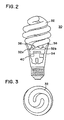
- a helical compact fluorescent lamp 30 is shown, having a lamp envelope or tube 32 in a coiled double helix configuration. End portions 32a, 32b enter the top portion 36 of the housing member 34; disposed within the end portions 32a, 32b are electrodes 38 which are electrically coupled to a ballast circuit arrangement 40 mounted within housing member 34.
Landscapes
- Vessels And Coating Films For Discharge Lamps (AREA)
- Manufacture Of Electron Tubes, Discharge Lamp Vessels, Lead-In Wires, And The Like (AREA)
- Formation Of Various Coating Films On Cathode Ray Tubes And Lamps (AREA)
Claims (12)
- Lampe à décharge à vapeur de mercure à basse pression comprenant une ampoule en verre tubulaire non droite comportant une partie courbée formée après une étape de revêtement, des moyens pour réaliser une décharge, une charge de remplissage de mercure entretenant la décharge et un gaz inerte scellé à l'intérieur de ladite ampoule, et une pluralité de couches de luminophores de terres rares déposées à l'intérieur de ladite ampoule, chacune de ladite pluralité de couches de luminophores (1) étant composée de particules de luminophores de terres rares, et (2) ayant une épaisseur de 1 à 3 particules, ladite pluralité de couches consistant en 2 à 6 couches.
- Lampe selon la revendication 1, chacune de ladite pluralité de couches de luminophores (1) ayant la même composition de luminophores de terres rares.
- Lampe selon la revendication 1 ou la revendication 2, chacune de ladite pluralité de couches de luminophores ayant un poids de revêtement de 1 à 2 mglcm2.
- Lampe selon l'une quelconque des revendications 1 à 3, ladite partie courbée de ladite ampoule de verre ayant un rayon de courbure intérieur inférieur à 15 cm.
- Lampe selon l'une quelconque des revendications 1 à 4, dans laquelle la dimension médiane des particules est de 1,5 à 9 microns.
- Lampe selon l'une quelconque des revendications 1 à 5, dans laquelle l'épaisseur totale des revêtements des couches de luminophores est de 4 à 8 particules.
- Lampe selon l'une quelconque des revendications 1 à 6, dans laquelle la pluralité de couches de luminophores a un poids total de revêtement d'au moins 2,6 mg/cm2.
- Procédé de fabrication d'une lampe à décharge à vapeur de mercure à basse pression comprenant les étapes consistant à : déposer une pluralité de couches de luminophores de terres rares à l'intérieur dudit tube en verre droit, chacune de ladite pluralité de couches de luminophores (1) étant composée de particules de luminophores de terres rares, et (2) ayant une épaisseur de 1 à 3 particules, ladite pluralité de couches consistant en 2 à 6 couches; après ladite étape de revêtement, donner au tube de verre la forme d'une ampoule en verre non droite, et incorporer ladite ampoule en verre dans une lampe à décharge à vapeur de mercure à basse pression.
- Procédé selon la revendication 8, chacune de ladite pluralité de couches de luminophores ayant la même composition de luminophores de terres rares.
- Procédé selon la revendication 8 ou la revendication 9, chacune de ladite pluralité de couches de luminophores ayant un poids de revêtement de 1 à 2 mg/cm2.
- Procédé selon l'une quelconque des revendications 8 à 10, ladite partie courbée de ladite ampoule en verre ayant un rayon de courbure inférieur à 15 cm.
- Procédé selon l'une quelconque des revendications 8 à 11, dans lequel chacune de ladite pluralité de couches de luminophores a un poids de revêtement compris dans une fourchette présélectionnée, ladite fourchette présélectionnée étant de 1 à 2 mg/cm2 lorsque la dimension médiane des particules est de 4 microns et la densité des particules est de 5 g/cm3, lorsque ladite dimension médiane des particules n'est pas de 4 microns ladite fourchette présélectionnée est obtenue en multipliant 1 à 2 mg/cm2 par le rapport de la densité des particules à 5 g/cm3, à condition toutefois que, si la dimension médiane des particules n'est pas de 4 microns et la densité des particules n'est pas de 5 g/cm3, les deux calculs sont exécutés pour obtenir la fourchette présélectionnée.
Applications Claiming Priority (2)
| Application Number | Priority Date | Filing Date | Title |
|---|---|---|---|
| US08/644,441 US5731659A (en) | 1996-05-13 | 1996-05-13 | Fluorescent lamp with phosphor coating of multiple layers |
| US644441 | 1996-05-13 |
Publications (2)
| Publication Number | Publication Date |
|---|---|
| EP0807958A1 EP0807958A1 (fr) | 1997-11-19 |
| EP0807958B1 true EP0807958B1 (fr) | 2002-10-30 |
Family
ID=24584920
Family Applications (1)
| Application Number | Title | Priority Date | Filing Date |
|---|---|---|---|
| EP97303239A Expired - Lifetime EP0807958B1 (fr) | 1996-05-13 | 1997-05-13 | Lampe fluorescente ayant un revêtement luminescent multicouche |
Country Status (5)
| Country | Link |
|---|---|
| US (2) | US5731659A (fr) |
| EP (1) | EP0807958B1 (fr) |
| JP (1) | JP3934736B2 (fr) |
| CN (1) | CN1170107A (fr) |
| DE (1) | DE69716667T2 (fr) |
Families Citing this family (39)
| Publication number | Priority date | Publication date | Assignee | Title |
|---|---|---|---|---|
| DE19755680A1 (de) * | 1997-12-15 | 1999-06-17 | Holzer Walter Prof Dr H C Ing | Einseitig gesockeltes Gasentladungsgefäß für Energiesparlampen |
| US6452324B1 (en) | 2000-08-30 | 2002-09-17 | General Electric Company | Fluorescent lamp for grocery lighting |
| US6525460B1 (en) | 2000-08-30 | 2003-02-25 | General Electric Company | Very high color rendition fluorescent lamps |
| US6583566B1 (en) * | 2000-10-27 | 2003-06-24 | General Electric Company | Low wattage fluorescent lamp having improved phosphor layer |
| JP4116808B2 (ja) | 2001-11-14 | 2008-07-09 | 松下電器産業株式会社 | 電球形蛍光ランプ |
| US20080029145A1 (en) * | 2002-03-08 | 2008-02-07 | Chien-Min Sung | Diamond-like carbon thermoelectric conversion devices and methods for the use and manufacture thereof |
| JPWO2003083896A1 (ja) * | 2002-03-28 | 2005-08-04 | 松下電器産業株式会社 | 電球形蛍光ランプ(compactself−ballastedfluorescentlamp)、蛍光ランプ(fluorescentlamp)及び螺旋形ガラス管(helicalglasstube)の製造方法 |
| US6820997B2 (en) * | 2002-05-21 | 2004-11-23 | Mofid Bissada | Lighting system and lamp with optimal position placement for television, news and motion picture studio |
| WO2003102464A1 (fr) * | 2002-06-04 | 2003-12-11 | Luna Glow Pty Ltd | Protege-lampe ou revetement phosphorescent |
| JP4820051B2 (ja) * | 2002-06-12 | 2011-11-24 | パナソニック株式会社 | 発光管、発光管の製造方法及び低圧水銀ランプ |
| US7053555B2 (en) * | 2002-11-21 | 2006-05-30 | Matsushita Electric Industrial Co., Ltd. | Arc tube, discharge lamp, and production method of such arc tube, which enables brighter illuminance |
| JPWO2004049388A1 (ja) * | 2002-11-22 | 2006-03-30 | 東芝ライテック株式会社 | 蛍光ランプおよび照明器具 |
| US6867536B2 (en) * | 2002-12-12 | 2005-03-15 | General Electric Company | Blue-green phosphor for fluorescent lighting applications |
| US20040113539A1 (en) * | 2002-12-12 | 2004-06-17 | Thomas Soules | Optimized phosphor system for improved efficacy lighting sources |
| US6965193B2 (en) * | 2002-12-12 | 2005-11-15 | General Electric Company | Red phosphors for use in high CRI fluorescent lamps |
| JP3687851B2 (ja) | 2003-01-28 | 2005-08-24 | 松下電器産業株式会社 | 発光管の製造方法 |
| US7088038B2 (en) * | 2003-07-02 | 2006-08-08 | Gelcore Llc | Green phosphor for general illumination applications |
| US6992432B1 (en) | 2003-07-24 | 2006-01-31 | General Electric Company | Fluorescent lamp |
| US6952081B1 (en) | 2003-07-31 | 2005-10-04 | General Electric Company | Fluorescent lamp having ultraviolet reflecting layer |
| JP2007520042A (ja) * | 2004-01-30 | 2007-07-19 | コーニンクレッカ フィリップス エレクトロニクス エヌ ヴィ | 低圧水銀蒸気蛍光ランプ |
| JP2005276515A (ja) * | 2004-03-23 | 2005-10-06 | Matsushita Electric Ind Co Ltd | 発光管、低圧水銀放電ランプ及び照明装置 |
| JP2006085943A (ja) * | 2004-09-14 | 2006-03-30 | Matsushita Electric Ind Co Ltd | 発光管、蛍光ランプ及び照明装置 |
| JP2006140083A (ja) * | 2004-11-15 | 2006-06-01 | Tohoku Univ | 蛍光ランプ |
| JP2006202668A (ja) * | 2005-01-24 | 2006-08-03 | Toshiba Lighting & Technology Corp | 蛍光ランプ、蛍光ランプ装置及び照明器具 |
| US7648649B2 (en) * | 2005-02-02 | 2010-01-19 | Lumination Llc | Red line emitting phosphors for use in led applications |
| US20070114562A1 (en) * | 2005-11-22 | 2007-05-24 | Gelcore, Llc | Red and yellow phosphor-converted LEDs for signal applications |
| US7497973B2 (en) * | 2005-02-02 | 2009-03-03 | Lumination Llc | Red line emitting phosphor materials for use in LED applications |
| US7358542B2 (en) * | 2005-02-02 | 2008-04-15 | Lumination Llc | Red emitting phosphor materials for use in LED and LCD applications |
| US7274045B2 (en) * | 2005-03-17 | 2007-09-25 | Lumination Llc | Borate phosphor materials for use in lighting applications |
| JP4963821B2 (ja) * | 2005-10-18 | 2012-06-27 | 株式会社オーク製作所 | 放電灯の封止構造 |
| US20070170834A1 (en) * | 2006-01-25 | 2007-07-26 | General Electric Company | High output fluorescent lamp with improved phosphor layer |
| US20070170863A1 (en) * | 2006-01-25 | 2007-07-26 | General Electric Company | High output fluorescent lamp |
| CN101038839B (zh) * | 2006-03-16 | 2012-05-23 | 陈枕流 | 一种超细管径荧光灯管的先弯管后涂粉制作方法 |
| JP2008226492A (ja) * | 2007-03-08 | 2008-09-25 | Hitachi Displays Ltd | 蛍光ランプ及びそれを用いた画像表示装置 |
| WO2009012301A2 (fr) * | 2007-07-16 | 2009-01-22 | Lumination Llc | Substance fluorescente à base de fluorure complexe émettant une ligne rouge activée avec mn4+ |
| US20090079324A1 (en) * | 2007-09-20 | 2009-03-26 | Istvan Deme | Fluorescent lamp |
| US7834533B2 (en) * | 2008-02-27 | 2010-11-16 | General Electric Company | T8 fluorescent lamp |
| JP5332711B2 (ja) * | 2009-02-23 | 2013-11-06 | 日亜化学工業株式会社 | 蛍光ランプ及び蛍光ランプの製造方法 |
| US8704438B2 (en) * | 2011-05-13 | 2014-04-22 | General Electric Company | Lamp with phosphor composition for improved lumen performance, and method for making same |
Family Cites Families (17)
| Publication number | Priority date | Publication date | Assignee | Title |
|---|---|---|---|---|
| US3707642A (en) * | 1970-08-31 | 1972-12-26 | Westinghouse Electric Corp | Vapor lamp which incorporates a special phosphor coating |
| US4088923A (en) * | 1974-03-15 | 1978-05-09 | U.S. Philips Corporation | Fluorescent lamp with superimposed luminescent layers |
| US4069441A (en) * | 1974-05-06 | 1978-01-17 | U.S. Philips Corporation | Electric gas discharge lamp having two superposed luminescent layers |
| US4347460A (en) * | 1980-03-03 | 1982-08-31 | Gte Products Corporation | Compact fluorescent lamp assembly |
| US4678966A (en) * | 1980-06-13 | 1987-07-07 | Gte Products Corporation | Fluorescent lamp having two phosphor layers |
| US4384237A (en) * | 1980-10-20 | 1983-05-17 | Gte Products Corporation | Fluorescent lamp containing adhesive frit in phosphor coating |
| US4393330A (en) * | 1980-10-20 | 1983-07-12 | North American Philips Electric Corp. | Method for effectively contacting manganese-activated zinc silicate phosphor with antimony oxide during phosphor coating, and resulting lamp |
| JPS57174847A (en) * | 1981-04-22 | 1982-10-27 | Mitsubishi Electric Corp | Fluorescent discharge lamp |
| US4363998A (en) * | 1981-05-19 | 1982-12-14 | Westinghouse Electric Corp. | Fluorescent lamp processing which improves performance of zinc silicate phosphor used therein |
| JPS6142851A (ja) * | 1984-08-02 | 1986-03-01 | Matsushita Electronics Corp | 螢光ランプ |
| US4623816A (en) * | 1985-04-22 | 1986-11-18 | General Electric Company | Fluorescent lamp using multi-layer phosphor coating |
| US4847533A (en) * | 1986-02-05 | 1989-07-11 | General Electric Company | Low pressure mercury discharge fluorescent lamp utilizing multilayer phosphor combination for white color illumination |
| US5045752A (en) * | 1989-10-24 | 1991-09-03 | General Electric Company | Minimizing mercury condensation in two layer fluorescent lamps |
| JP3149444B2 (ja) * | 1991-01-30 | 2001-03-26 | 東芝ライテック株式会社 | 低圧水銀蒸気放電灯 |
| EP0540788A1 (fr) * | 1991-11-04 | 1993-05-12 | Toshiba Lighting & Technology Corporation | Méthode de formation de deux couches d'enduction sur un tube, fabrication d'une lampe ayant les deux couches d'enduction et lampe fabriquée ainsi |
| US5258689A (en) * | 1991-12-11 | 1993-11-02 | General Electric Company | Fluorescent lamps having reduced interference colors |
| DE69630068T2 (de) * | 1995-03-31 | 2004-06-17 | General Electric Co. | Leuchtstofflampe |
-
1996
- 1996-05-13 US US08/644,441 patent/US5731659A/en not_active Expired - Lifetime
-
1997
- 1997-05-12 JP JP12052197A patent/JP3934736B2/ja not_active Expired - Fee Related
- 1997-05-13 DE DE69716667T patent/DE69716667T2/de not_active Expired - Lifetime
- 1997-05-13 EP EP97303239A patent/EP0807958B1/fr not_active Expired - Lifetime
- 1997-05-13 CN CN97113088A patent/CN1170107A/zh active Pending
- 1997-10-24 US US08/957,572 patent/US5944572A/en not_active Expired - Fee Related
Also Published As
| Publication number | Publication date |
|---|---|
| CN1170107A (zh) | 1998-01-14 |
| EP0807958A1 (fr) | 1997-11-19 |
| US5731659A (en) | 1998-03-24 |
| US5944572A (en) | 1999-08-31 |
| DE69716667D1 (de) | 2002-12-05 |
| JPH1050259A (ja) | 1998-02-20 |
| DE69716667T2 (de) | 2003-06-12 |
| JP3934736B2 (ja) | 2007-06-20 |
Similar Documents
| Publication | Publication Date | Title |
|---|---|---|
| EP0807958B1 (fr) | Lampe fluorescente ayant un revêtement luminescent multicouche | |
| US4079288A (en) | Alumina coatings for mercury vapor lamps | |
| US5552665A (en) | Electric lamp having an undercoat for increasing the light output of a luminescent layer | |
| EP0762479A2 (fr) | Lampe fluorescente munie d'une couche de réflexion des rayons ultraviolettes | |
| KR100879529B1 (ko) | 수은 증기 방전등 | |
| GB1578246A (en) | Fluorescent lighting | |
| EP0295140B1 (fr) | Lampe fluorescente à index du rendu des couleurs prédéterminé et méthode de fabrication | |
| US4088802A (en) | Process for coating envelope for reflector-type fluorescent lamp and the lamp resulting therefrom | |
| WO2002050870A1 (fr) | Lampe colortone fluorescente a mercure reduit | |
| DE19721432A1 (de) | Elektroden und Lampen | |
| JPH0217908B2 (fr) | ||
| US6605888B1 (en) | Metal halide lamp with enhanced red emission, in excess of a blackbody | |
| EP1547125A2 (fr) | Lampes fluorescentes a vapeur de mercure a basse pression | |
| US6362570B1 (en) | High frequency ferrite-free electrodeless flourescent lamp with axially uniform plasma | |
| US6548965B1 (en) | Electrodeless fluorescent lamp with low wall loading | |
| JP2004516622A (ja) | 水銀が減少したカラートーン蛍光灯 | |
| EP1932167A2 (fr) | Lampes fluorescentes consommant peu de mercure et possedant une couche contenant phosphore/alumine | |
| EP1323181B1 (fr) | Lampe a decharge basse pression a tres haute puissance (vho) | |
| JP3374612B2 (ja) | 蛍光ランプの製造方法 | |
| JPH0432500B2 (fr) | ||
| EP0607061A1 (fr) | Lampe à décharge de grande intensité | |
| EP0540788A1 (fr) | Méthode de formation de deux couches d'enduction sur un tube, fabrication d'une lampe ayant les deux couches d'enduction et lampe fabriquée ainsi | |
| DE3324081A1 (de) | Quecksilberdampfhochdruckentladungslampe | |
| JPH0589841A (ja) | 低圧水銀蒸気放電ランプ |
Legal Events
| Date | Code | Title | Description |
|---|---|---|---|
| PUAI | Public reference made under article 153(3) epc to a published international application that has entered the european phase |
Free format text: ORIGINAL CODE: 0009012 |
|
| AK | Designated contracting states |
Kind code of ref document: A1 Designated state(s): DE FR GB IT |
|
| 17P | Request for examination filed |
Effective date: 19980519 |
|
| 17Q | First examination report despatched |
Effective date: 19991227 |
|
| GRAG | Despatch of communication of intention to grant |
Free format text: ORIGINAL CODE: EPIDOS AGRA |
|
| GRAG | Despatch of communication of intention to grant |
Free format text: ORIGINAL CODE: EPIDOS AGRA |
|
| GRAH | Despatch of communication of intention to grant a patent |
Free format text: ORIGINAL CODE: EPIDOS IGRA |
|
| GRAH | Despatch of communication of intention to grant a patent |
Free format text: ORIGINAL CODE: EPIDOS IGRA |
|
| GRAA | (expected) grant |
Free format text: ORIGINAL CODE: 0009210 |
|
| AK | Designated contracting states |
Kind code of ref document: B1 Designated state(s): DE FR GB IT |
|
| PG25 | Lapsed in a contracting state [announced via postgrant information from national office to epo] |
Ref country code: IT Free format text: LAPSE BECAUSE OF FAILURE TO SUBMIT A TRANSLATION OF THE DESCRIPTION OR TO PAY THE FEE WITHIN THE PRE;WARNING: LAPSES OF ITALIAN PATENTS WITH EFFECTIVE DATE BEFORE 2007 MAY HAVE OCCURRED AT ANY TIME BEFORE 2007. THE CORRECT EFFECTIVE DATE MAY BE DIFFERENT FROM THE ONE RECORDED.SCRIBED TIME-LIMIT Effective date: 20021030 Ref country code: FR Free format text: LAPSE BECAUSE OF FAILURE TO SUBMIT A TRANSLATION OF THE DESCRIPTION OR TO PAY THE FEE WITHIN THE PRESCRIBED TIME-LIMIT Effective date: 20021030 |
|
| REG | Reference to a national code |
Ref country code: GB Ref legal event code: FG4D |
|
| REF | Corresponds to: |
Ref document number: 69716667 Country of ref document: DE Date of ref document: 20021205 |
|
| EN | Fr: translation not filed | ||
| PLBE | No opposition filed within time limit |
Free format text: ORIGINAL CODE: 0009261 |
|
| STAA | Information on the status of an ep patent application or granted ep patent |
Free format text: STATUS: NO OPPOSITION FILED WITHIN TIME LIMIT |
|
| 26N | No opposition filed |
Effective date: 20030731 |
|
| PGFP | Annual fee paid to national office [announced via postgrant information from national office to epo] |
Ref country code: GB Payment date: 20130528 Year of fee payment: 17 Ref country code: DE Payment date: 20130530 Year of fee payment: 17 |
|
| REG | Reference to a national code |
Ref country code: DE Ref legal event code: R119 Ref document number: 69716667 Country of ref document: DE |
|
| GBPC | Gb: european patent ceased through non-payment of renewal fee |
Effective date: 20140513 |
|
| REG | Reference to a national code |
Ref country code: DE Ref legal event code: R119 Ref document number: 69716667 Country of ref document: DE Effective date: 20141202 |
|
| PG25 | Lapsed in a contracting state [announced via postgrant information from national office to epo] |
Ref country code: DE Free format text: LAPSE BECAUSE OF NON-PAYMENT OF DUE FEES Effective date: 20141202 |
|
| PG25 | Lapsed in a contracting state [announced via postgrant information from national office to epo] |
Ref country code: GB Free format text: LAPSE BECAUSE OF NON-PAYMENT OF DUE FEES Effective date: 20140513 |