EP0807913A1 - Système de surveillance - Google Patents
Système de surveillance Download PDFInfo
- Publication number
- EP0807913A1 EP0807913A1 EP97108018A EP97108018A EP0807913A1 EP 0807913 A1 EP0807913 A1 EP 0807913A1 EP 97108018 A EP97108018 A EP 97108018A EP 97108018 A EP97108018 A EP 97108018A EP 0807913 A1 EP0807913 A1 EP 0807913A1
- Authority
- EP
- European Patent Office
- Prior art keywords
- signal
- video
- synchronous
- monitoring unit
- lines
- Prior art date
- Legal status (The legal status is an assumption and is not a legal conclusion. Google has not performed a legal analysis and makes no representation as to the accuracy of the status listed.)
- Ceased
Links
- 230000001360 synchronised effect Effects 0.000 claims abstract description 19
- 230000005540 biological transmission Effects 0.000 claims abstract description 10
- 238000012544 monitoring process Methods 0.000 claims description 25
- 230000008878 coupling Effects 0.000 claims description 10
- 238000010168 coupling process Methods 0.000 claims description 10
- 238000005859 coupling reaction Methods 0.000 claims description 10
- 238000011084 recovery Methods 0.000 abstract 1
- 238000005516 engineering process Methods 0.000 description 2
- 238000012806 monitoring device Methods 0.000 description 2
- 230000001419 dependent effect Effects 0.000 description 1
- 238000011161 development Methods 0.000 description 1
- 230000018109 developmental process Effects 0.000 description 1
- 238000010586 diagram Methods 0.000 description 1
- 238000012986 modification Methods 0.000 description 1
- 230000004048 modification Effects 0.000 description 1
- 230000008054 signal transmission Effects 0.000 description 1
- 238000001228 spectrum Methods 0.000 description 1
Images
Classifications
-
- G—PHYSICS
- G08—SIGNALLING
- G08B—SIGNALLING OR CALLING SYSTEMS; ORDER TELEGRAPHS; ALARM SYSTEMS
- G08B13/00—Burglar, theft or intruder alarms
- G08B13/18—Actuation by interference with heat, light, or radiation of shorter wavelength; Actuation by intruding sources of heat, light, or radiation of shorter wavelength
- G08B13/189—Actuation by interference with heat, light, or radiation of shorter wavelength; Actuation by intruding sources of heat, light, or radiation of shorter wavelength using passive radiation detection systems
- G08B13/194—Actuation by interference with heat, light, or radiation of shorter wavelength; Actuation by intruding sources of heat, light, or radiation of shorter wavelength using passive radiation detection systems using image scanning and comparing systems
- G08B13/196—Actuation by interference with heat, light, or radiation of shorter wavelength; Actuation by intruding sources of heat, light, or radiation of shorter wavelength using passive radiation detection systems using image scanning and comparing systems using television cameras
- G08B13/19634—Electrical details of the system, e.g. component blocks for carrying out specific functions
-
- G—PHYSICS
- G08—SIGNALLING
- G08B—SIGNALLING OR CALLING SYSTEMS; ORDER TELEGRAPHS; ALARM SYSTEMS
- G08B13/00—Burglar, theft or intruder alarms
- G08B13/18—Actuation by interference with heat, light, or radiation of shorter wavelength; Actuation by intruding sources of heat, light, or radiation of shorter wavelength
- G08B13/189—Actuation by interference with heat, light, or radiation of shorter wavelength; Actuation by intruding sources of heat, light, or radiation of shorter wavelength using passive radiation detection systems
- G08B13/194—Actuation by interference with heat, light, or radiation of shorter wavelength; Actuation by intruding sources of heat, light, or radiation of shorter wavelength using passive radiation detection systems using image scanning and comparing systems
- G08B13/196—Actuation by interference with heat, light, or radiation of shorter wavelength; Actuation by intruding sources of heat, light, or radiation of shorter wavelength using passive radiation detection systems using image scanning and comparing systems using television cameras
- G08B13/19639—Details of the system layout
- G08B13/19645—Multiple cameras, each having view on one of a plurality of scenes, e.g. multiple cameras for multi-room surveillance or for tracking an object by view hand-over
-
- H—ELECTRICITY
- H04—ELECTRIC COMMUNICATION TECHNIQUE
- H04N—PICTORIAL COMMUNICATION, e.g. TELEVISION
- H04N23/00—Cameras or camera modules comprising electronic image sensors; Control thereof
- H04N23/60—Control of cameras or camera modules
- H04N23/66—Remote control of cameras or camera parts, e.g. by remote control devices
-
- H—ELECTRICITY
- H04—ELECTRIC COMMUNICATION TECHNIQUE
- H04N—PICTORIAL COMMUNICATION, e.g. TELEVISION
- H04N5/00—Details of television systems
- H04N5/04—Synchronising
- H04N5/06—Generation of synchronising signals
- H04N5/067—Arrangements or circuits at the transmitter end
- H04N5/073—Arrangements or circuits at the transmitter end for mutually locking plural sources of synchronising signals, e.g. studios or relay stations
-
- H—ELECTRICITY
- H04—ELECTRIC COMMUNICATION TECHNIQUE
- H04N—PICTORIAL COMMUNICATION, e.g. TELEVISION
- H04N7/00—Television systems
- H04N7/18—Closed-circuit television [CCTV] systems, i.e. systems in which the video signal is not broadcast
- H04N7/181—Closed-circuit television [CCTV] systems, i.e. systems in which the video signal is not broadcast for receiving images from a plurality of remote sources
Definitions
- the invention relates to a monitoring system according to the preamble of claim 1.
- Such video surveillance systems with several video cameras and a central monitoring unit are known.
- the previous surveillance systems use a second line, via which the synchronization signal is transmitted from the synchronous source, for example provided at the central monitoring unit, to the video cameras.
- This two-line technology is complex.
- the object of the invention is to show a system which avoids this disadvantage.
- the system according to the invention only requires a line between each video camera and the central monitoring unit. This line is used to transmit the video signal, and at the same time to transmit the synchronous signal to the respective camera.
- the synchronizing signal or the signal corresponding to this synchronizing signal can be coupled in at any point on the respective line, with this synchronizing signal also being present at a spatial distance between the device for coupling in the synchronizing signal via the lines the central monitoring unit can be transmitted.
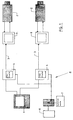
- 1 is a central video monitoring unit, which is shown as a monitor for the sake of simplicity.
- a plurality of video cameras 2 are connected to this central monitoring unit 1, each via a single line 3, which on the one hand for transmitting the image data from the camera 2 to the monitoring unit 1 and on the other hand for transmitting a synchronization signal from a source for this synchronization signal from the monitoring unit 1 to the respective video camera 2.
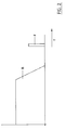
- the transmission of the synchronization signal takes place by means of a carrier frequency F which is modulated with the synchronization signal and which is outside of the frequency range B of the video signal.
- the bandwidth of the video signal is between 0 and 6 MHz, for example.
- the carrier frequency F lies then clearly above the upper frequency of the video tape, ie for example at 8 MHz.
- a coupling filter 4 is provided in each line, which is controlled by a modulator 5 which modulates the carrier frequency supplied by the oscillator 6 with the synchronizing signal of the synchronizing signal source 7.
- a coupling filter 4 is provided for each line 3, while the modulator 5, the oscillator 6 and the source 7 for the synchronous signal are provided jointly for all lines.
- the monitoring device 1 is of course also synchronized with the synchronization signal of the synchronization signal source 7, for example via an internal connection, if the device 8 for coupling the synchronization signal into the lines 3 is part of the monitoring unit 1.
- the coupling filter 4, the modulator 5, the oscillator 6 and the synchronous source 7 form the unit for coupling the synchronization signal.
- Each camera 2 has a filter demodulator 9 which is connected to the line 3 and, as a low-pass filter, allows the video signal of the respective camera 2 to pass unhindered.
- the synchronization signal is demodulated and fed to the respective camera 2.
- All cameras 2 of the monitoring system are thus operated with one and the same synchronization signal, so that the video signals supplied by the cameras also have one and the same synchronization and thus, inter alia, at the central one Monitoring unit 1 can be switched from one video camera to another video camera without the image displayed on the monitor of the monitoring unit 1 being synchronized again or the image falling over or running briefly.
- the particular advantage is that for each camera two only one line is required and the previously common and necessary two-line technology is avoided. If the synchronization signal is also transmitted to the monitoring unit 1 via the lines 3 or one of these lines, a filter demodulator 9 is of course also provided on the monitoring unit in order to recover the synchronization signal for synchronization of the monitoring unit.
Landscapes
- Engineering & Computer Science (AREA)
- Multimedia (AREA)
- Signal Processing (AREA)
- Physics & Mathematics (AREA)
- General Physics & Mathematics (AREA)
- Closed-Circuit Television Systems (AREA)
Applications Claiming Priority (2)
| Application Number | Priority Date | Filing Date | Title |
|---|---|---|---|
| DE29608957U DE29608957U1 (de) | 1996-05-18 | 1996-05-18 | Video-Überwachungssystem |
| DE29608957U | 1996-05-18 |
Publications (1)
| Publication Number | Publication Date |
|---|---|
| EP0807913A1 true EP0807913A1 (fr) | 1997-11-19 |
Family
ID=8024118
Family Applications (1)
| Application Number | Title | Priority Date | Filing Date |
|---|---|---|---|
| EP97108018A Ceased EP0807913A1 (fr) | 1996-05-18 | 1997-05-16 | Système de surveillance |
Country Status (2)
| Country | Link |
|---|---|
| EP (1) | EP0807913A1 (fr) |
| DE (1) | DE29608957U1 (fr) |
Cited By (3)
| Publication number | Priority date | Publication date | Assignee | Title |
|---|---|---|---|---|
| GB2344713A (en) * | 1998-02-10 | 2000-06-14 | Furuno Electric Co | Display system |
| DE10007266A1 (de) * | 2000-02-17 | 2001-09-13 | Vtq Videotronik Gmbh | Komplexes bidirektionales Kontroll- und Überwachungssystem |
| WO2003032641A3 (fr) * | 2001-10-04 | 2003-07-17 | Siemens Ag | Systeme et procede de transmission de donnees numeriques |
Citations (3)
| Publication number | Priority date | Publication date | Assignee | Title |
|---|---|---|---|---|
| FR1557116A (fr) * | 1967-12-27 | 1969-02-14 | ||
| DE2917978A1 (de) * | 1979-05-04 | 1980-11-06 | Volker Joachim Remme | Kabelkommunikationssystem |
| WO1996003005A1 (fr) * | 1994-07-15 | 1996-02-01 | Isec Intelligent Security Ab | Systeme de surveillance par television |
Family Cites Families (9)
| Publication number | Priority date | Publication date | Assignee | Title |
|---|---|---|---|---|
| US4190863A (en) * | 1977-05-23 | 1980-02-26 | Rca Corporation | Remote control system for a television camera |
| JPH0671313B2 (ja) * | 1983-08-12 | 1994-09-07 | エルベックスビデオ株式会社 | 情報伝達システムのための外部同期方法およびその装置 |
| AT382054B (de) * | 1985-05-03 | 1987-01-12 | Norma Gmbh | Leitungsgebundenes uebertragungssystem fuer fernsehsignale |
| JP2528789B2 (ja) * | 1985-06-26 | 1996-08-28 | 中央電子 株式会社 | 映像情報管理装置 |
| DD250015A1 (de) * | 1986-06-12 | 1987-09-23 | Junkalor Dessau | Schaltungsanordnung zur externen synchronisierung einer oder mehrerer videokameras |
| US4860101A (en) * | 1987-11-06 | 1989-08-22 | Vicon Industries, Inc. | Central station synchronization system |
| JPH01220993A (ja) * | 1988-02-29 | 1989-09-04 | Erubetsukusu Video Kk | 閉回路テレビジョン装置 |
| US5249051A (en) * | 1991-12-09 | 1993-09-28 | Elbex Video Ltd. | Method and apparatus for converting synchronizing signal for television cameras |
| US5335014A (en) * | 1992-09-24 | 1994-08-02 | Elbex Video, Ltd. | Method and apparatus for remote synchronous switching of video transmitters |
-
1996
- 1996-05-18 DE DE29608957U patent/DE29608957U1/de not_active Expired - Lifetime
-
1997
- 1997-05-16 EP EP97108018A patent/EP0807913A1/fr not_active Ceased
Patent Citations (3)
| Publication number | Priority date | Publication date | Assignee | Title |
|---|---|---|---|---|
| FR1557116A (fr) * | 1967-12-27 | 1969-02-14 | ||
| DE2917978A1 (de) * | 1979-05-04 | 1980-11-06 | Volker Joachim Remme | Kabelkommunikationssystem |
| WO1996003005A1 (fr) * | 1994-07-15 | 1996-02-01 | Isec Intelligent Security Ab | Systeme de surveillance par television |
Cited By (4)
| Publication number | Priority date | Publication date | Assignee | Title |
|---|---|---|---|---|
| GB2344713A (en) * | 1998-02-10 | 2000-06-14 | Furuno Electric Co | Display system |
| GB2344713B (en) * | 1998-02-10 | 2003-05-07 | Furuno Electric Co | Display system |
| DE10007266A1 (de) * | 2000-02-17 | 2001-09-13 | Vtq Videotronik Gmbh | Komplexes bidirektionales Kontroll- und Überwachungssystem |
| WO2003032641A3 (fr) * | 2001-10-04 | 2003-07-17 | Siemens Ag | Systeme et procede de transmission de donnees numeriques |
Also Published As
| Publication number | Publication date |
|---|---|
| DE29608957U1 (de) | 1996-10-31 |
Similar Documents
| Publication | Publication Date | Title |
|---|---|---|
| DE69835046T2 (de) | Video-Überwachungsvorrichtung | |
| DE2224353A1 (de) | Verfahren zur Signalübertragung für Trägerfrequenzsysteme | |
| DE1919215C3 (de) | Datenübertragungssystem | |
| DE1248708B (de) | Schaltungsanordnung m einem Farbfernsehempfänger mit zellensequentieller Umschaltung zur Synchronisierung der Um schaltphase des Farbsynchronimpulses | |
| EP0807913A1 (fr) | Système de surveillance | |
| DE2522332A1 (de) | Codierer und decodierer fuer ein system zur verbreitung von audio-visuellen farbfernsehsignalen | |
| DE69213821T2 (de) | Multiplexübertragungssystem | |
| DE2221888A1 (de) | Farbfernsehempfaenger fuer Pal- und Secam-Norm | |
| DE19628540A1 (de) | Verfahren zum Übertragen von digitalen Daten zwischen Fernsehempfängern und Videorecordern | |
| DE2920303C2 (de) | Vorrichtung zum Übertragen von Videosignalen | |
| EP0158770A2 (fr) | Méthode de modulation et de démodulation synchrone suivant le principe de la modulation/balayage "offset" pour télévision couleurs et appareil utilisant cette méthode | |
| DE3789498T2 (de) | Mac-format mit alternierenden gleichstrompegel- und taktwiedergewinnungssignalen. | |
| EP0915578B1 (fr) | Système de télécommunication mobile numérique et procédé TDMA | |
| DE1562187A1 (de) | Farbfernseh-Empfaenger | |
| DE69221381T2 (de) | Nachrichtenübertragungssteuerschaltung für Überwachungsfernsehkamera | |
| WO1992009153A1 (fr) | Procede pour la transmission simultanee de donnees sur un canal de transmission | |
| DE914262C (de) | Einseitenband-Traegerfrequenz-Fernsprechsystem | |
| DE2305463C3 (de) | Aufzeichnungsträger, auf dem eine Fernsehaufzeichnung gespeichert ist, Anwendungsverfahren für diesen Aufzeichnungsträger und Wiedergabegerät | |
| DE1280292B (de) | Verfahren zur automatischen Fernsynchronisierung von Aussenstellen von einer Zentralstelle fuer Farbfernsehsignale der PAL-Art | |
| DE1537104B2 (de) | Verfahren zur uebertragung der synchronisierinformation einschliesslich des farbtraegers zu oder in einem farbfern sehstudio | |
| DE2354257C3 (fr) | ||
| DE2149215A1 (de) | System zur UEberwachung ortsveraenderlicher Funkstellen | |
| EP0130588B1 (fr) | Procédé et dispositif pour adapter le rapport des mots de données d'image d'un décodeur/codeur du système PAL à la fréquence d'horloge de traitement d'un dispositif de traitement vidéo | |
| DE2354257B2 (de) | Verfahren zur gemeinsamen uebertragung und zum gemeinsamen empfang eines fernseh- und eines zusatzsignales und vorrichtung zur durchfuehrung des verfahrens | |
| DE3204507C2 (de) | Hochfrequenzübertragungssystem |
Legal Events
| Date | Code | Title | Description |
|---|---|---|---|
| PUAI | Public reference made under article 153(3) epc to a published international application that has entered the european phase |
Free format text: ORIGINAL CODE: 0009012 |
|
| AK | Designated contracting states |
Kind code of ref document: A1 Designated state(s): AT CH DE LI |
|
| 17P | Request for examination filed |
Effective date: 19980121 |
|
| 17Q | First examination report despatched |
Effective date: 20010508 |
|
| STAA | Information on the status of an ep patent application or granted ep patent |
Free format text: STATUS: THE APPLICATION HAS BEEN REFUSED |
|
| 18R | Application refused |
Effective date: 20021125 |